

Page 1
1. Before installation (setup):
Remove lift components from the box and then assemble as instructed.
2. Installation and adjustment:
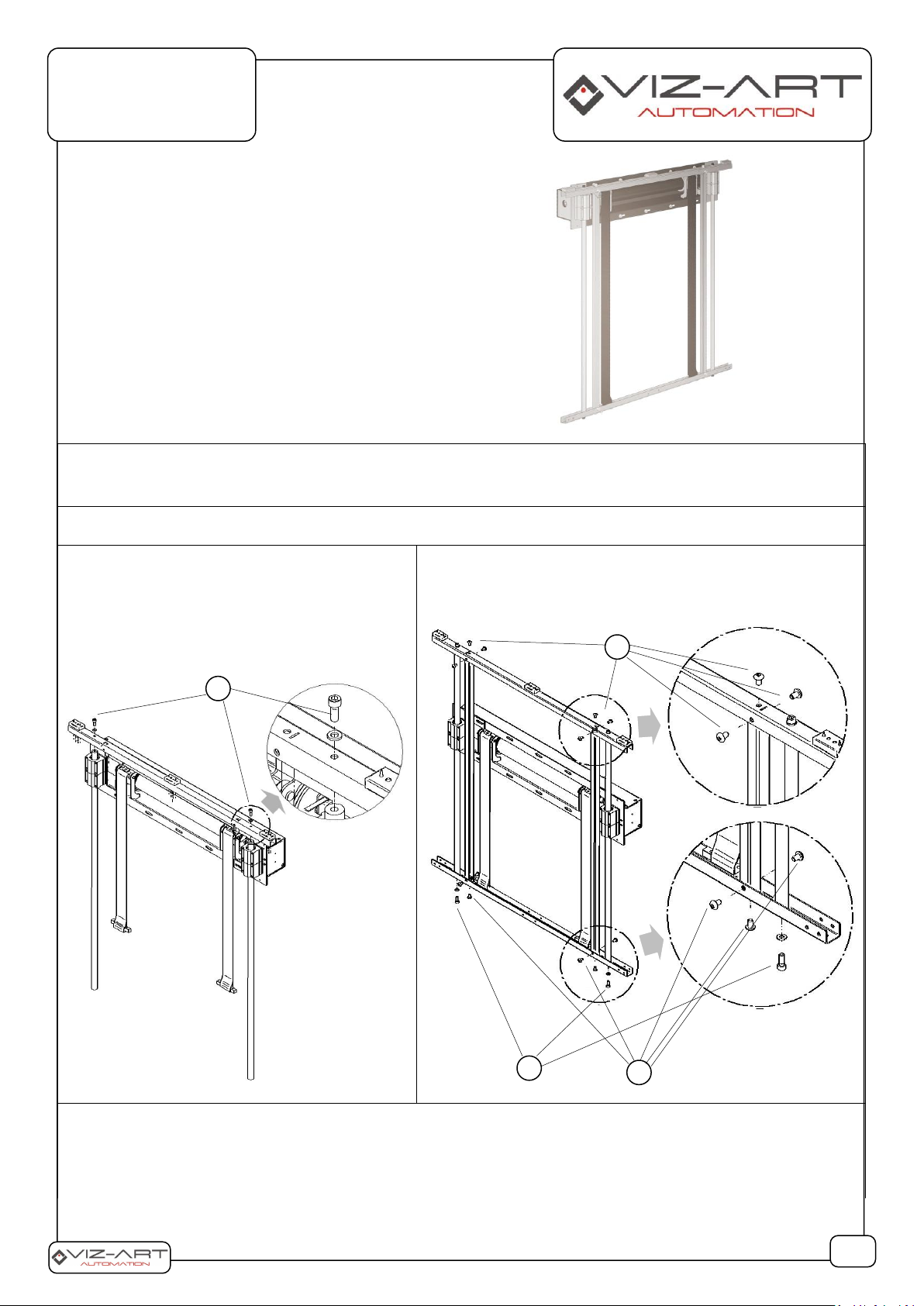
2A. Assemble frame components as show on
picture below
insert guideways through linear bearings. Using
hex key and 2 screws (A), join top element of
frame with both guideways.
2B. Fasten with 6 screws (B), to a top element of the frame.
Then, screw bottom element of frame with both
guideways, using 2 screws (C) and vertical elements of
the frame 6 screws (D) with hex key .
2C. Screw in the belt fastening (E) to bottom element of frame (F) using screws (C) and springs (D), starting from left
strap and then right strap.
ART-LIFT
Hide Your Media
A B A
B
1/6
LIST OF ITEMS:
ART-LIFT unit(1 pcs.)
Wall switch (1 pcs.)
Grinded guideways (2 pcs.)
Vertical frame elements (2 pcs.)
Horizontal frame elements: upper and lower (1 pcs.)
Screw set
Page 2
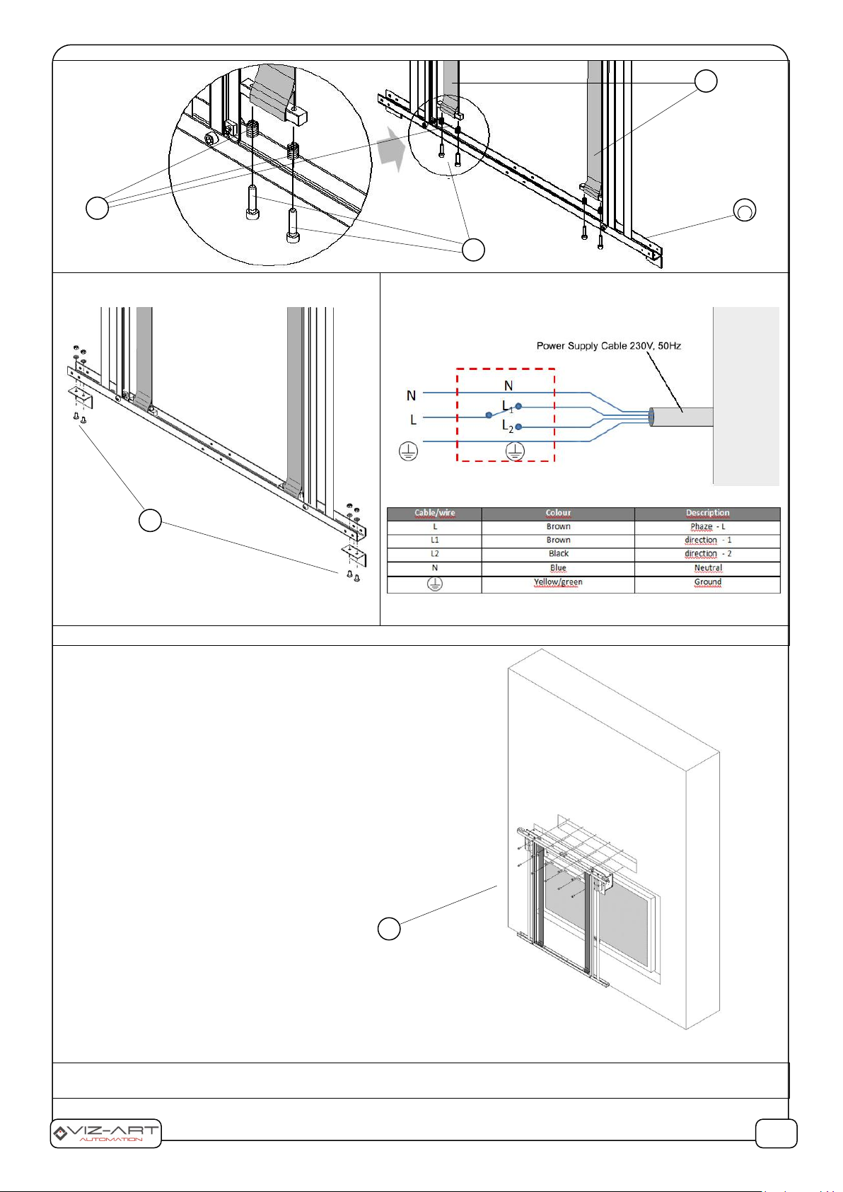
2D. Screw the brackets to the bottom element
with screws (G).
2E. Connect lift motor to power supply 230V, 50Hz as below:
3. Wall installation
In the previously prepared hole with dimensions: height
3A. Adjusting the tension of belt: by turning the adjusting screws, the tension of both straps should be adjusted so that
the weight hanging on the frame evenly tension the two straps.
F
E
2/6
C
D
H
G
100mm; depth: 75mm; width 705mm, install the lift
mechanism using appropriate screws / mounting pins (H)
to the wall (depends on the type of wall to which the lift is
installed). If it is necessary to use all 10 assembly points (5
upper and 5 lower ones).
Make sure that the lift is in position “Low”. Then adjust the
tension of both straps.
Page 3

3B. Adjusting position “up” and “low” of the frame.
Set the position of the picture / mirror mounted on the frame so that it fully covers your media at the “low” position fully
and reveals in the “up” position. Low position setting: Using the included hex key, adjust the "DOWN" limit switch. Turning
in the direction "+" we extend the lower position, turning in the direction "-" the lower position will be shortened.Setting
the upper position: Using the included ampoule key, adjust the "UP" limit switch. By turning in the "+" direction, we extend
the lift lifting range and by turning in the "-" direction we shorten the range of movement of ARTlift.
Mounting cover / picture / mirror on the frame
Center the cover/picture/mirror on a frame and mount it on mounting brackets on top element of the frame.
3/6
Page 4

3. Suggested wall mount for display – ZIP Plasma Mount
4/6
Page 5

4. List of components:
Art-lift components
1
lift
mechanism
2
grinded
guideways
3
top element
of the frame
4
bottom
element of
frame
5
vertical
element of
the frame
6
bracket
Manufactured by: VIZ-ART Automation
tel.+48 22/6138899 www.viz-art.eu
Screws in set
1
Cylindrical
Allen head
bolt M6 x 16 –
4pcs.
A
2
Flat washer
M6 - 16pcs.
3
Allen pan
head bolt
M6x10 - 2pcs.
B
4
Cylindrical
Allen head
bolt M6x50 –
4pcs.
C
5
Spring
ø8x14 – 4pcs.
D
6
Allen pan
head bolt
M5x12 - 4pcs.
8
dowel fi8 10pcs.
H
8
INIS KEO
5/6
Page 6

SAFETY INFORMATION CAUTION
To ensure safety of the personnel, make sure to follow the guidelines provided in this instruction manual. Keep the instruction manual for future reference.
• Do not allow children to play with the device controller (switch or remote control).
• Do not leave device controllers within the reach of children.
• Inspect the equipment assembly periodically to identify and repair any damages.
• If any damages are identified, do not use the equipment until the necessary repairs are made.
• Keep appropriate distance from the equipment during operation. In case of a failure, the equipment may constitute a risk of injury or wounds.
• Do not install any items other than those specified in the equipment instruction manual. All installation and mounting works should be done by an engineer with
appropriate licenses.
• Inappropriate mounting may damage the product or cause injury.
• Use only elements compliant with the mounting instructions.
• It is prohibited to perform any steps that may damage the power supply cord or plug.
• Do not modify the power cord, i.e. do not make any structural modifications, do not place the cord in immediate vicinity of hot objects, do not bend or twist the cord, do
not pull the cord, do not place any heavy objects on the cord, and do not coil the power cord.
• Using the equipment with a damaged power cord may cause electrocution or shorting of the circuits and fire.
• Do not touch the power cord or plug with wet hands.
• Always follow the guidelines provided in this instruction manual and in the equipment mounting instructions.
• Before installing the equipment, make sure it is complete, free of defects, compliant with your order, and has not sus tained damage in transport.
INSTALLATION GUIDELINES
• The equipment should be installed by a qualified engineer, in accordance with the guidelines provided in the mounting instructions. Electrical connections should be
made by a specialist with an appropriate license.
• Install the equipment using screws and mounting elements appropriate for the conditions of the installation, to which the lift is mounted, and stable, original auxiliary
elements, dedicated for the specific lift model.
• After mounting the equipment, before first use, check if it is mounted as per the instructions, and level. If the equipment is not level, adjust the mounting. Do not use
equipment that is not properly installed.
• Do not modify or unscrew elements of the equipment, as this may cause a risk of permanent damage to the equipment and/or the safety of the users.
WARRANTY CONDITIONS
The warranty period for the device is 24 months from the date of purchase indicated on the original receipt.
1) The warranty period for the device's electric drive is 60 months.
2) The warrantor commits to fix free of charge damage suffered by a device delivered to the service point that demonstrates defects resulting from defects in workmanship
or materials, which become noticeable during the warran ty period.
3) The warranty does not cover:
a) damage caused by use of the device in a manner other than that described in the user manual,
b) damage caused by improper storage or transport,
c) mechanical damage,
d) abrupt changes in electrical grid voltage,
e) disassembly and reassembly,
4) Defects will be removed within 14 days from the date the device is ac-cepted on warranty at a service point.
5) Service point address
Manufactured after 13.08.2005.
Do not dispose of used electrical and electronic equipment together with municipal waste, due to the presence of substances hazardous to the environment in
the equipment. Such devices should be delivered to a collection point for recycling. Information on collection points is available from local government
authorities or in stores.
DECLARATION OF CONFORMITY
VIZ-ART AUTOMATION
I hereby declare, with sole responsibility, that the products:
TV & LCD lifts: V-LIFT VESA; VMAX - LIFT 95; F-lift 46; F-lift 65;
CP-LIFT S; CP-LIFT M; CP-LIFT L; SIDE LIFT 65; SMARTBOARD LIFT;
ADVANCED LCD Lift 17; ADVANCED LCD Lift 19; ADVANCED LCD Lift 24
to which this declaration relates, in accordance with:
the Low Voltage Directive 73/23EEC together with the modifications of Directive 93/68/EEC
EMC Directive 89/336/EEC along with its amendments92/31/EEC, 93/68/EEC i 91/263/EEC
comply with the following European standards:
EN 60335-2-97 with reference to EN 60335-1
EN 55014-1, EN 55014-2, EN 61000-3-2, EN 61000-3-3
and are CE certified.
 Loading...