

Viz-Art Automation SPAV Series, SPAV 30/420, SPAV 30/780, SPAV 30/1560, SPAV 30/1960 Installation Manual
...Page 1
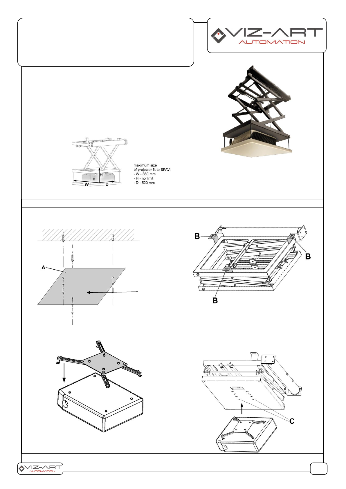
1. INSTALLATION:
A. Determine the mounting location for the lift in the
structural ceiling using the template (transport plate A). Drill
holes and insert wall plugs (included in the mounting kit).
B. Raise the lift and fit it to the structural ceiling using
screws (marked B).
C. Install the universal projector bracket using screws included
in the mounting kit.
D. Mount the projector along with the mounting
component (adaptor) to the base of the lift –
mechanical platform. “C” openings in the platform
allow you to adjust the projector mounting distance.
1/5
SPAV LIFT
Projector lift:
•SPAV 30/420; •SPAV 30/780; •SPAV 30/1560; •SPAV 30/1960;
•SPAV 30/2800; •SPAV 30/3500; •SPAV 30/4200
3 or 4
points
mounting
system
LIST OF COMPONENTS:
Lift
Ceiling closure panel
Push-button switch
Installation template
Installation manual
Mounting kit
Page 2
E. Turn on the projector and adjust the position of image on
the screen by rotating the adaptor.
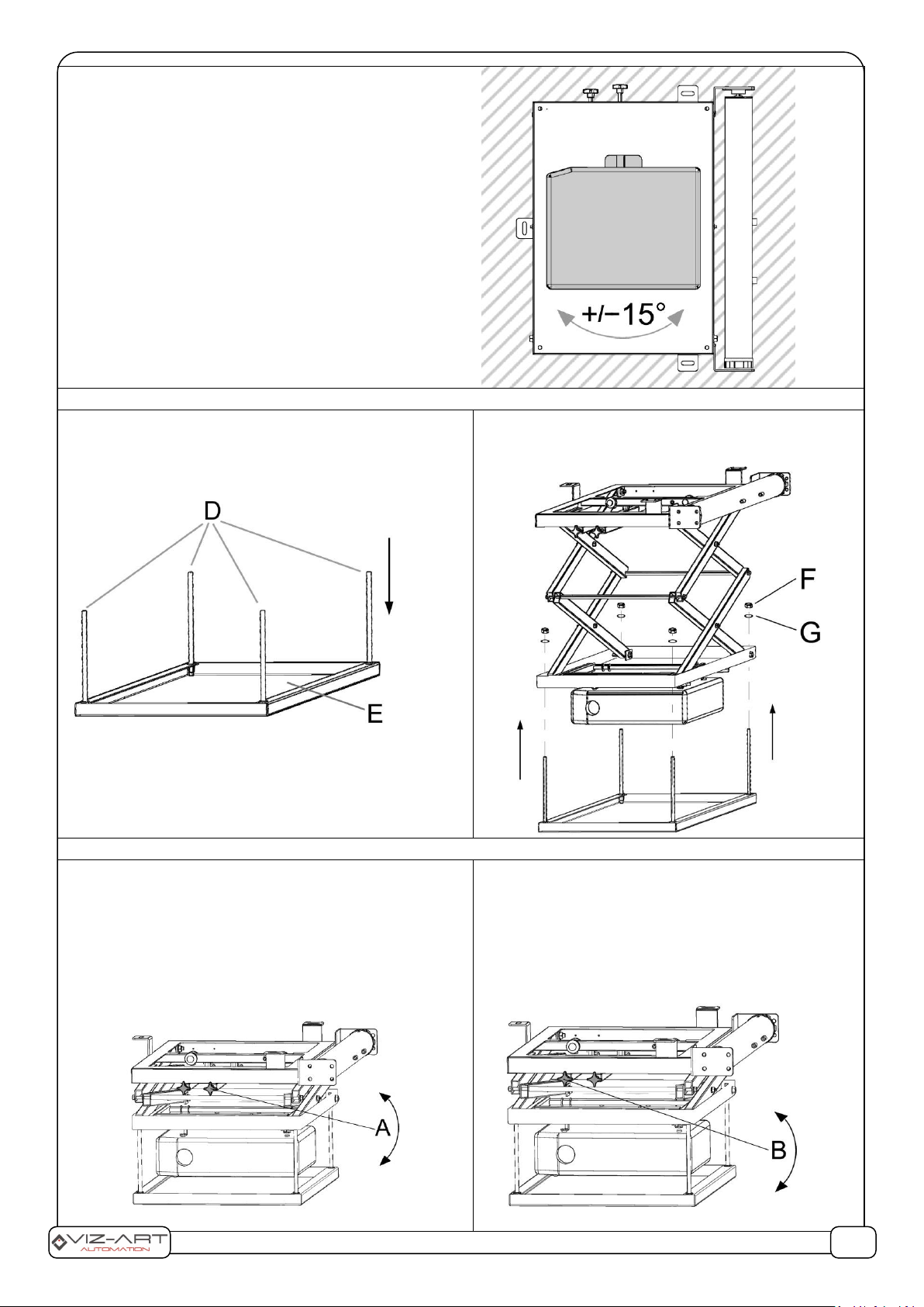
2. MOUNTING THE CLOSURE PANEL:
A. Screw threaded studs D – 4 pcs (included in the kit) – into
closure panel openings – marked E.
Note! The opening, through which the lift slides out of the
suspended ceiling must be larger by 6-10 mm for each side of
the ceiling closure panel.
B. Mount the panel along with studs to the mobile
platform of the lift and tighten nuts F – 4 pcs (included
in the kit), also using washers „G”.
3. SETTINGS AND ADJUSTMENT:
1. TOP STOP (the lift with the projector are retracted above
the ceiling).
Adjustment knob – marked A – is used to adjust the top
stop position. Turn knob A clockwise in order to raise the
lift’s top stop. Turn knob A anti-clockwise in order to lower
the lift’s top stop.
Set limit switches using knob A so that, after the lift stops,
the closure panel is flush with the suspended ceiling – as
shown in the drawing.
2. BOTTOM STOP (the lift with the projector are lowered
to the operating position).
Turn adjustment knob B clockwise in order to raise the
lift’s stop. Turn knob B anti-clockwise in order to lower
the lift’s stop.
Set limit switches using knob B so that, after the lift
stops, the projector displays the image evenly on the
screen.
2/4
Page 3

4. PROTECTIVE MEASURES:
A. THERMAL – switches the motor off after 4 minutes of
continuous lift operation. After the motor overheats and
turns off automatically, do not turn on the lift for approx.
10-15 minutes.
B. MOTOR LIMIT SWITCHES. The lift is equipped with
drive limit switches, which determine the lift’s top and
bottom stop positions.
Note! Adjusting sealed drive switches is prohibited!!
C. EMERGENCY BRAKE. In the event of a power outage, the lift
will stop immediately. The device will continue operating
upon restoring power.
5. ELECTRICAL CONNECTION
A. Only persons with appropriate authorization may connect the lift to a 230V power supply. The connection must follow the
diagram and the instructions.
6. TECHNICAL DATA:
Extension:
420 mm - SPAV 30/420
780 mm - SPAV 30/780
560 mm - SPAV 30/1560
1960 mm - SPAV 30/1960
2800 mm - SPAV 30/2800
3500 mm - SPAV 30/3500
4200 mm - SPAV 30/4200
Capacity:
30kg
Adjustment of settings:
Wyłączniki krańcowe – góra – dół.
Obrót projektora +/- 15°.
Odległość od ekranu.
Power supply:
230V / 50 HZ
Manufacturer: VIZ-ART Automation
tel.+48 22/6138899 www.viz-art.eu
3/4
Page 4

Rules of safe operation of VIZ-ART AUTOMATION equipment.
4/4
SAFETY INFORMATION CAUTION
To ensure safety of the personnel, make sure to follow the guidelines provided in this instruction manual. Keep the instruction manual for future reference.
• Do not allow children to play with the device controller (switch or remote control).
• Do not leave device controllers within the reach of children.
• Inspect the equipment assembly periodically to identify and repair any damages.
• If any damages are identified, do not use the equipment until the necessary repairs are made.
• Keep appropriate distance from the equipment during operation. In case of a failure, the equipment may constitute a risk of injury or wounds.
• Do not install any items other than those specified in the equipment instruction manual. All installation an d mounting works should be done by an engineer with
appropriate licenses.
• Inappropriate mounting may damage the product or cause injury.
• Use only elements compliant with the mounting instructions.
• It is prohibited to perform any steps that may damage the power supply cord or plug.
• Do not modify the power cord, i.e. do not make any structural modifications, do not place the cord in immediate vicinity of hot objects, do not bend or twist the cord, do
not pull the cord, do not place any heavy objects o n the cord, and do not coil the power cord.
• Using the equipment with a damaged power cord may cause electrocution or shorting of the circuits and fire.
• Do not touch the power cord or plug with wet hands.
• Always follow the guidelines provided in this instruction manual and in the equipment mounting instructions.
• Before installing the equipment, make sure it is complete, free of defects, compliant with your order, and has not sustained damage in transport.
INSTALLATION GUIDELINES
• The equipment should be installed by a qualified engineer, in accordance with the guidelines provided in the mounting instructions. Electrica l connections should be
made by a specialist with an appropriate license.
• Install the equipment using screws and mounting elements appropriate for the conditions of the installation, to which the lift is mounted, and stable, original auxiliary
elements, dedicated for the specific lift model.
• After mounting the equipment, before first use, check if it is mounted as per the instructions, and level. If the equipment is not level, adjust the mounting. Do not use
equipment that is not properly installed.
• Do not modify or unscrew elements of the equipment, as this may cause a risk of permanent damage to the equipment and/or the safety of the users.
WARRANTY CONDITIONS
The warranty period for the device is 24 months from the date of purchase indicated on the original receipt.
1) The warranty period for the device's electric drive is 60 months.
2) The warrantor commits to fix free of charge damage suffered by a device delivered to the service point that demonstrates defects resulting from defects in workmanship
or materials, which become noticeable during the warranty period.
3) The warranty does not cover:
a) damage caused by use of the device in a manner other than that described in the user manual,
b) damage caused by improper storage or transport,
c) mechanical damage,
d) abrupt changes in electrical grid voltage,
e) disassembly and reassembly,
4) Defects will be removed within 14 days from the date the device is ac-cepted on warranty at a service point.
5) Service point address
Manufactured after 13.08.2005.
Do not dispose of used electrical and electronic equipment together with municipal waste, due to the presence of substances hazardous to the environment in
the equipment. Such devices should be delivered to a collection point for recycling. Information on collection points is available from local government
authorities or in stores.
DECLARATION OF CONFORMITY
VIZ-ART AUTOMATION
I hereby declare, with sole responsibility, that the products:
Lifts: SIMPLE Slim 9/350; SIMPLE Slim 15/350; UP-LIFT; CINE-LIFT; CINEMAX-LIFT;
SLIM LIFT 12/1640; SLIM LIFT 10/3250; SPAV 30/420; SPAV 30/780; SPAV 30/1560; SPAV 30/1960; SPAV
30/2800; SPAV 30/3500; SPAV 30/4200; SPAVMAX 60/420; SPAVMAX 60/780; SPAVMAX 60/1560; SPAVMAX
60/1960; SPAVMAX 60/2800; SPAVMAX 60/3500; SPAVMAX 60/4200; MAX-LIFT 130/4500; MAX-LIFT 130/6500
to which this declaration relates, in accordance with:
the Low Voltage Directive 73/23EEC together with the modifications of Directive 93/68/EEC
EMC Directive 89/336/EEC along with its amendments92/31/EEC, 93/68/EEC i 91/263/EEC
comply with the following European standards:
EN 60335-2-97 with reference to EN 60335-1
EN 55014-1, EN 55014-2, EN 61000-3-2, EN 61000-3-3
and are CE certified.
 Loading...