

Page 1
1. PREPARATIONS FOR MOUNTING:
a. The CP-lift can only be opened in the "Locking Plate" position!
b. Opening the CP-lift in a different position than "Locking Plate" down, may cause serious damage to the device !!!
c. Unscrew the lid of the box – 1
d. Unscrew the sides of the box – 2
e. Place the CP-lift with "Locking Plate" down so that the CP-lift can be opened - Minimum 140 cm from the Ground
f. Connect the lift to the power supply (230-240V 50Hz) Neutral - Blue / Power-Brown / Ground-Yellow: Green / and open
the lift to 70% of full opening, by connecting WHITE + RED control cables in POTENTIAL FREE CONTROL wire . Use the
diagram - electrical connection.
g. Take off the "Locking Plate" and remove the transport protection and the "White Masking Plate" masking plate.
h. After removing components needed to next steps of installation, close the CP-lift, by connecting WHITE + BLUE control
cables in POTENTIAL FREE CONTROL wire.
9. Unplug CP-lift wires from supply.
2. INSTALLATION and ADJUSTMENTS:
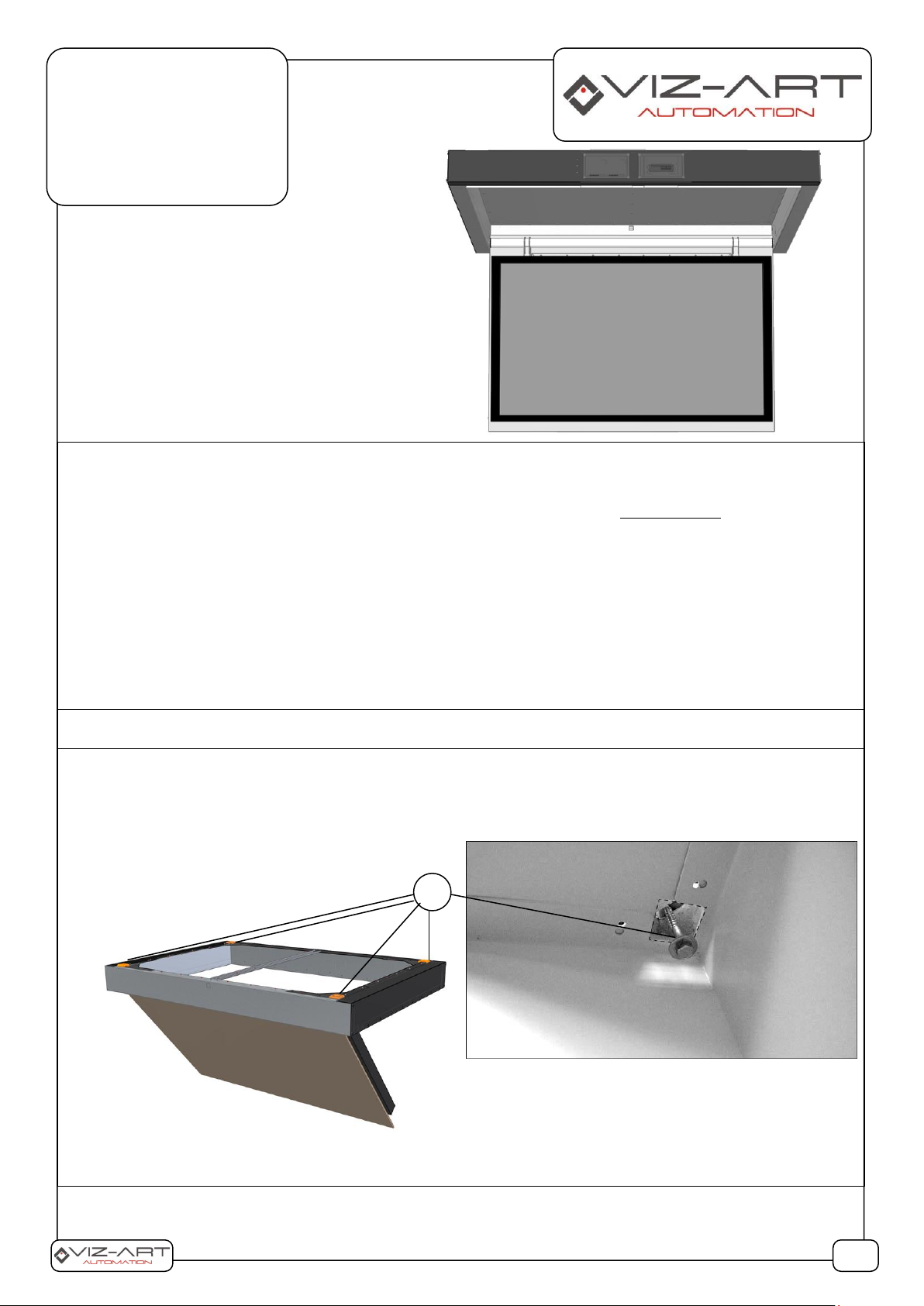
2A. a. Determine the location for mounting the CP-LIFT lift and drill 4 holes in the ceiling. Use a proper dowels and
screws for the installation surface is the responsibility of the installation team).
b. Insert bolts into dowels through the lift's slotted openings (A) and tighten them securely, Checking proper (axis
X,Y ) leveling when installing the lift to a ceiling.
CP-LIFT
Ceiling lift models:
CP-LIFT - M
CP-LIFT - L
A
1/6
LIST OF ITEMS:
Lift for plasma TV;
LCD/TV bracket;
LCD/TV mounting kit;
Installation manual
Page 2
2B. Once the lift is mounted on the ceiling, fix the white masking plate (B) by inserting through its openings the plastic
fastening rivets (incl. in the mounting kit).
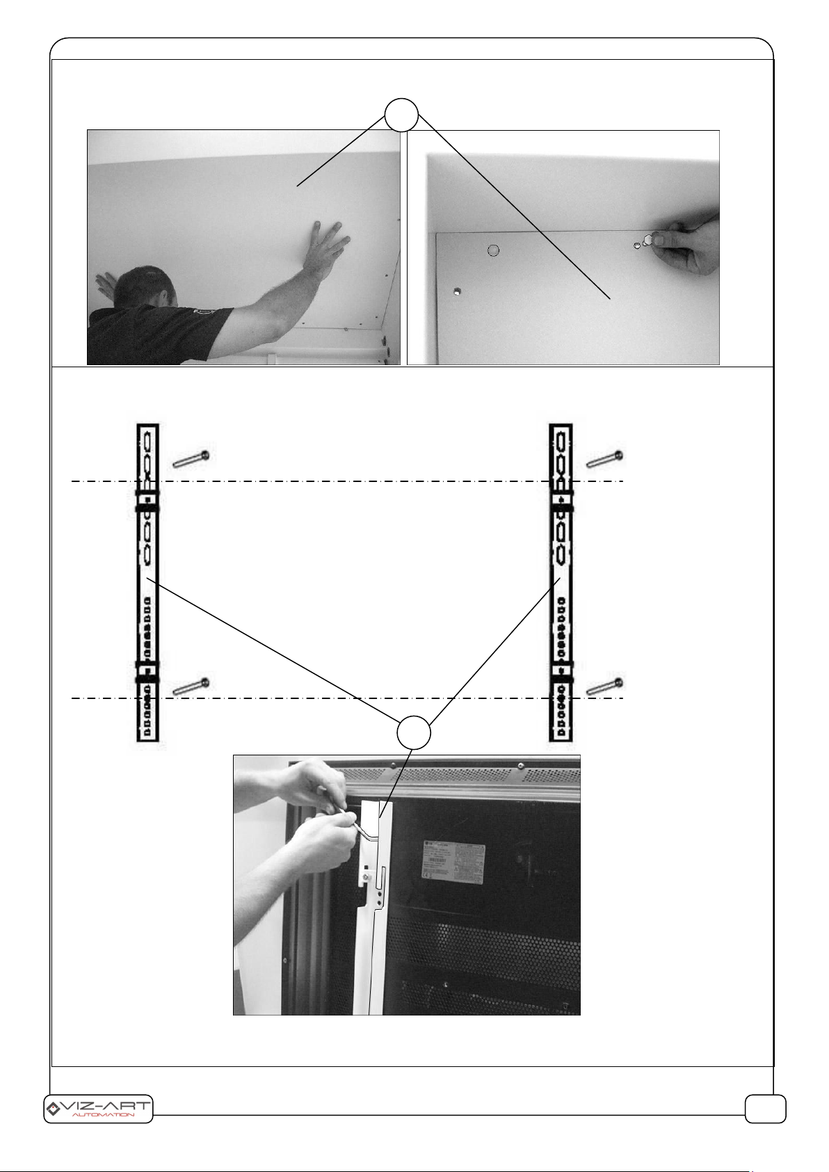
2C. Attach the 2 elements of the TV bracket (C) to the Display/LCD/ TV mounting points. Ensure that the screws are
inserted at same level in both bracket elements.
PLEASE NOTE: The safety of users and devices depends on the proper installation of the lift and TV. Select the
fastening screws for the TV in accordance with the TV manufacturer's recommendations.
B
C
2/6
Page 3

2D. a. In order to mount the TV, connect the lift to a power supply and swing the movable arm of the lift, so that it is
perpendicular to the floor.
b. Install the TV together with the mounting on the movable lift arm (D) and place it in the center, so that the
television is located in the central part of the arm (D).
c. Carefully close the lift, ensuring that the TV is hidden symmetrically in the CP lift Locking Plate, which protects
the TV after the lift closes.
d. Tighten the lock screws (E) with a hex key.
e. Connect power supply cable and signal cables to the TV through the opening (F) in the housing of the CP-LIFT lift
(attach them to the housing with a cable tie).
E
D
F
3/6
G
Page 4

2E. a. Open CP lift to 70% of Total opening to install Locking plate comfortably.
b.Slide the white locking plate (G), so that the 4 mounts (H) slide over the pins (I).
c. Tighten screws (J) to secure the plate (G).
2F. SETTING THE OPEN AND CLOSE POSITION OF THE CP-LIFT LIFT:
LIFTS OPEN - SETTING:
1. Open the lift to the desired position and adjust the Lower limit switch to a expected TV position. (use a size 10 hex
key).
2. By turning the key in the "+" direction you increase the lift opening angle (max 100°), while turning it towards "-"
reduces the lift opening angle.
LIFT CLOSING - SETTING:
1. Open the lift and adjust using the Upper limit switch.
2. Turning towards "+" closes more the lift, turning towards "-" swings it open.
J
4/6
I
H G H I J
Page 5

Programming the safety threshold of the engine load.
Before switching on the power, connect together 3 wires responsible for the potential-free control (A, B. GND)
Turn on the power.
The motors drive down twice (to the lower end position) and up (to the upper end position). The programming is
completed automatically after the actuators have completed the full two Bottom-Up cycles.
After programming, switch off the power supply and open the wires responsible for the potential-free control (A, B. GND).
Don't stop or touch when programming CP-lift, let it make full movement cycle.
ATTENTION
The emergency shutdown of the engine under load only works when driving up and beyond the angle of 22 degrees (from
the bottom vertical position)
3. ELECTRIC CONNECTION - CONTROL DIAGRAM:
Manufacturer: VIZ-ART Automation
tel.+48 22/6138899 www.viz-art.eu
5/6
Upper control – Closing adjustment
When turned clockwise - Less
When turned counterclockwise – More
Lower control –Opening adjustment
When turned clockwise - More
When turned counterclockwise - Less
Page 6

Rules of safe operation of VIZ-ART AUTOMATION equipment.
6/6
SAFETY INFORMATION CAUTION
To ensure safety of the personnel, make sure to follow the guidelines provided in this instruction manual. Keep the instruction manual for future reference.
• Do not allow children to play with the device c ontroller (switch or remote control).
• Do not leave device controllers within the reach of children.
• Inspect the equipment assembly periodically to identify and repair any damages.
• If any damages are identified, do not use the equipment until the necessary repairs are made.
• Keep appropriate distance from the equipment during operation. In case of a failure, the equipment may constitute a risk of injury or wounds.
• Do not install any items other than those specified in the equipment instruction manual. All installation and mounting works should be done by an engineer with
appropriate licenses.
• Inappropriate mounting may damage the product or cause injury.
• Use only elements compliant with the mounting instructions.
• It is prohibited to perform any steps that may damage the power supply cord or plug.
• Do not modify the power cord, i.e. do not make any structural modifications, do not place the cord in immediate vicinity of hot objects, do not bend or twist the cord, do
not pull the cord, do not place any heavy objects on the cord, and do not coil the power cord.
• Using the equipment with a damaged power cord may cause electrocution or shorting of the circuits and fire.
• Do not touch the power cord or plug with wet hands.
• Always follow the guidelines provided in this instruction manual and in the equipment mounting instructions.
• Before installing the equipment, make sure it is complete, free of defects, compliant with your order, and has not sustained damage in transport.
INSTALLATION GUIDELINES
• The equipment should be installed by a qualified engineer, in accordance with the guidelines provided in the mounting instructions. Electrical connections should be
made by a specialist with an appropriate license.
• Install the equipment using screws and mounting elements appropriate for the conditions of the installation, to which the lift is mounted, and stable, orig inal auxiliary
elements, dedicated for the specific lift model.
• After mounting the equipment, before first use, check if it is mounted as per the instructions, and level. If the equipment is not level, adjust the mounting. Do not use
equipment that is not properly installed.
• Do not modify or unscrew elements of the equipment, as this may cause a risk of permanent damage to the equipment and/or the safety of the users.
WARRANTY CONDITIONS
The warranty period for the device is 24 months from the date of purchase indicated on the original receipt.
1) The warranty period for the device's electric drive is 60 months.
2) The warrantor commits to fix free of charge damage suffered by a device delivered to the service point that demonstrates defects resulting from defects in workmanship
or materials, which become noticeable during the warranty period.
3) The warranty does not cover:
a) damage caused by use of the device in a manner other than that described in the user manual,
b) damage caused by improper storage or transport,
c) mechanical damage,
d) abrupt changes in electrical grid voltage,
e) disassembly and reassembly,
4) Defects will be removed within 14 days from the date the device is ac-cepted on warranty at a service point.
5) Service point address
Manufactured after 13.08.2005.
Do not dispose of used electrical and electronic equipment together with municipal waste, due to t he presence of substances hazardous to the environment in
the equipment. Such devices should be delivered to a collection point for recycling. Information on collection points is available from local government
authorities or in stores.
DECLARATION OF CONFORMITY
VIZ-ART AUTOMATION
I hereby declare, with sole responsibility, that the products:
TV Lifts: V-LIFT VESA; VMAX - LIFT 95; F-lift 46; F-lift 65;
CP-LIFT S; CP-LIFT M; CP-LIFT L; SIDE LIFT 65; SMARTBOARD LIFT;
ADVANCED LCD Lift 17; ADVANCED LCD Lift 19; ADVANCED LCD Lift 24
to which this declaration relates, in accordance with:
the Low Voltage Directive 73/23EEC together with the modifications of Directive 93/68/EEC
EMC Directive 89/336/EEC along with its amendments92/31/EEC, 93/68/EEC i 91/263/EEC
comply with the following European standards:
EN 60335-2-97 with reference to EN 60335-1
EN 55014-1, EN 55014-2, EN 61000-3-2, EN 61000-3-3
and are CE certified.
 Loading...