

Vix Technology PCP6100 User Manual

PCP6100
USER MANUAL
Document No.
Revision
Revision Date
VXP-00356
2.0
26 May 2016

The information contained in this document is copyright and may not be
reproduced, stored in a retrieval system or transmitted in any form or by
any means in whole or in part without the express written consent of Vix
IP Pty Ltd.
This material is also confidential and may not be disclosed in whole or
part to any third party nor used in any manner whatsoever other than for
a purpose expressly consented to by Vix IP Pty Ltd in writing.

PCP6100
User Manual
VXP-00356
Revision 2.0
Page 3 of 33
© Vix IP Pty Ltd 2016
Vix IP Pty Ltd Confidential
Revision
Revision
Date
Description
Author
.1
19 May 2013
Initial Draft
Chris Bailye
.2
24/05/2013
Updated Power Supply to 24VDC device
Chris Bailye
.3
24/05/2013
Updated the data ports
Chris Bailye
1.0
26/05/2016
Updated to include FCC compliance statement
Gino Bertino
2.0
6/09/2016
Added FCC warning and RF exposure statement.
Gino Bertino
Document History

PCP6100
User Manual
VXP-00356
Revision 2.0
Page 4 of 33
© Vix IP Pty Ltd 2016
Vix IP Pty Ltd Confidential
Table of Contents
1 INTRODUCTION ............................................................................................................................ 6
1.1 PURPOSE ......................................................................................................................................... 6
1.2 SCOPE ............................................................................................................................................ 6
1.3 WHO SHOULD READ THIS MANUAL ........................................................................................................ 6
1.4 TERMINOLOGY .................................................................................................................................. 7
1.5 SAFETY ........................................................................................................................................... 7
1.5.1
Safety Precautions .................................................................................................................. 7
1.5.2
Warnings and Cautions ........................................................................................................... 8
1.5.3
EMC and Safety Standards Applied ........................................................................................... 8
1.5.3.1 FCC compliance statement ................................................................................................................ 9
1.5.3.2 Human exposure statement: ............................................................................................................. 9
2 OVERVIEW .................................................................................................................................. 10
2.1 INSTALLATION COMPONENT LIST ......................................................................................................... 11
2.2 INSTALLATION PROCESS .................................................................................................................... 12
3 MOUNTING DESIGN .................................................................................................................... 13
3.1 PCP6100 MOUNTING ....................................................................................................................... 13
3.2 TOOLS .......................................................................................................................................... 13
3.3 POSITIONING .................................................................................................................................. 14
3.3.1
General Mounting Procedure .................................................................................................. 15
3.3.2
Mounting Pole ....................................................................................................................... 15
3.3.3
Pole Mounting Procedure ....................................................................................................... 15
3.3.4
Wall Cradle ........................................................................................................................... 17
3.3.5
Wall Cradle Mounting Procedure ............................................................................................ 17
4 CABLE INSTALLATION ................................................................................................................ 19
4.1 PROCEDURE .................................................................................................................................... 19
4.2 TOOLS .......................................................................................................................................... 19
4.3 POWER SUPPLY CABLING ................................................................................................................... 19
4.4 POWER CABLE PIN-OUT .................................................................................................................... 19
4.5 NETWORK CABLE ............................................................................................................................. 20
4.6 NETWORK CABLE ASSEMBLY ............................................................................................................... 21
4.7 NETWORK CABLE PIN-OUT ................................................................................................................. 21
5 PCP6100 TERMINATION ............................................................................................................. 22
5.1 DATA PORTS .................................................................................................................................. 22
6 PCP6100 INSTALLATION ............................................................................................................ 23
6.1 TOOLS .......................................................................................................................................... 23
6.2 MOUNTING PCP6100 BASE PLATE ....................................................................................................... 23
6.3 LOCKING PCP6100 .......................................................................................................................... 23
7 CHANGING SAM .......................................................................................................................... 24
8 PCP6100 SOFTWARE INSTALLATION ......................................................................................... 25
8.1 REQUIRED EQUIPMENT ...................................................................................................................... 25
8.2 PROCEDURE .................................................................................................................................... 25
APPENDIX A ATTACHMENTS .......................................................................................................... 26
A.1 INSTALLATION GUIDES FOR POLE MOUNTED PCP6100 ............................................................................. 26
A.1.1
A.1.2
A.1.3
A.2 INSTALLATION GUIDES FOR WALL CRADLED PCP6100 .............................................................................. 30
Single Head Pole Mounted PCP6100 ....................................................................................... 27
Pole Mounting Details ............................................................................................................ 28
Installation Pole Electrical ...................................................................................................... 29

PCP6100
User Manual
VXP-00356
Revision 2.0
Page 5 of 33
© Vix IP Pty Ltd 2016
Vix IP Pty Ltd Confidential
A.2.1
A.3 SPECIAL INSTALLATION TOOLS ............................................................................................................ 32
APPENDIX B EXTERNAL CONNECTOR DESCRIPTIONS .................................................................. 33
B.1 24VDC POWER ................................................................................................................................ 33
B.2 100BASET NETWORK ....................................................................................................................... 33
B.3 AUXILIARY COMMUNICATIONS ............................................................................................................. 33
Wall Mount Bracket 90° ......................................................................................................... 31
List of Tables
TABLE 1: TERMINOLOGY .................................................................................................................................... 7
TABLE 2: COMPONENTS REQUIRED TO INSTALL THE PCP6100 VALIDATOR .................................................................... 11
TABLE 3: DC POWER ...................................................................................................................................... 33
TABLE 4: NETWORK LAN ................................................................................................................................. 33
List of Figures
FIGURE 1: PCP6100 VALIDATOR ......................................................................................................................... 6
FIGURE 2: PCP6100 VALIDATOR MOUNTED ON SUPPORT POLE .................................................................................. 14
FIGURE 3: PCP6100 MOUNTING POLE. ................................................................................................................ 15
FIGURE 4: 250MM PCD ................................................................................................................................... 16
FIGURE 5: BASE COVER .................................................................................................................................... 16
FIGURE 6: WALL CRADLE ASSEMBLY .................................................................................................................... 17
FIGURE 7: TYPICAL CLIENT ENCLOSURE AND WALL MOUNTED BRACKET AWAITING VALIDATOR INSTALLATION.......................... 18
FIGURE 8: POWER & NETWORK SUPPLY CABLING ................................................................................................... 20
FIGURE 9: POWER CABLE AND NETWORK CABLE AT THE POLE, READY TO BE CONNECTED TO THE VALIDATOR .......................... 21
FIGURE 10: PCP6100 POWER AND NETWORK CONNECTIONS .................................................................................... 22
FIGURE 11: LOCK COVER FITTED ........................................................................................................................ 23
FIGURE 12: LOCATION OF SAM SLOTS. ................................................................................................................ 24
PCP6100
User Manual
VXP-00356
Revision 2.0
Page 6 of 33
© Vix IP Pty Ltd 2016
Vix IP Pty Ltd Confidential
1 Introduction
This installation guide provides the instructions for installing and setting up a PCP6100
also known as the PCP5700.EMV. From here on in, this document will refer to the unit
simply as the PCP6100.
1.1 Purpose
The purpose of this document is to provide general installation guidelines for the
PCP6100 Validator. It includes instructions for mechanical installation, cabling, testing,
and configuration procedures.
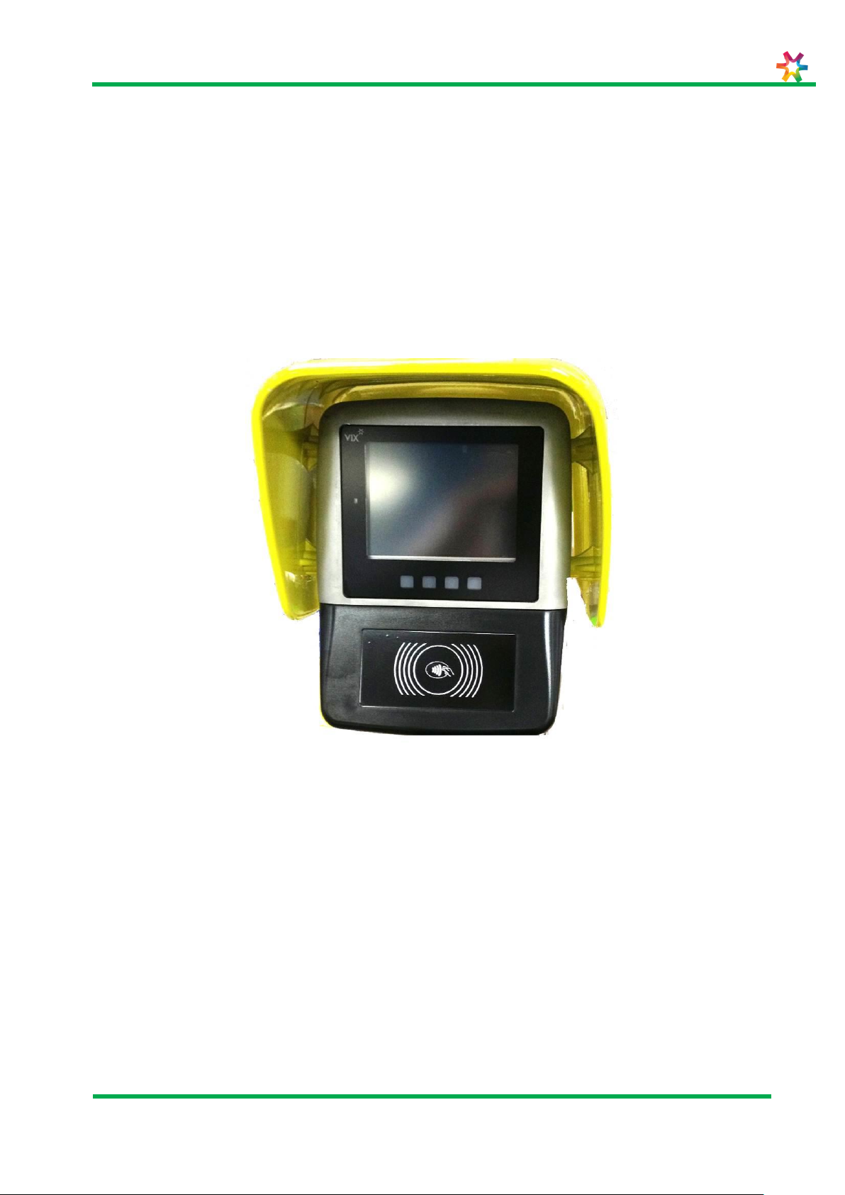
Figure 1 shows the PCP6100 Validator.
Figure 1: PCP6100 Validator
1.2 Scope
The scope of the document is limited to describing the installation guidelines for the
PCP6100 only. This manual is to be used by Supervisors and Technicians performing on
site installations.
1.3 Who Should Read This Manual
This document is intended for use by technicians installing PCP6100 Validator units, such
as:
Installation personnel
Work on mounting, commissioning and removal, primarily of the operational
apparatus systems.

PCP6100
User Manual
VXP-00356
Revision 2.0
Page 7 of 33
© Vix IP Pty Ltd 2016
Vix IP Pty Ltd Confidential
Term
Definition
AFC
Automatic Fare Collection
AS
Australian Standard
BoM
Bill of Materials
CF
Compact Flash memory card
DC
Direct Current
DHCP
Dynamic Host Configuration Protocol
HBOM
Hardware Bill Of Materials
HD
Hot Dipped (galvanising)
LAN
Local Area Network
LCD
Liquid Crystal Display
OD
Outside Diameter
OS
Operating System
PC
Personal Computer (desktop or compatible)
PCD
Pitch Circle Diameter
PCP6100
Validator
PVC
Poly Vinyl Chloride
RS232
Serial Communications Standard
SBOM
Software Bill Of Materials
SP
Service Pack (of an operating system)
SSH
Secure Shell network protocol
UD
Usage Data
WXP
Windows XP operating system (desktop edition)
1.4 Terminology
The following table contains a list of common acronyms/terms and their meanings.
Table 1: Terminology
1.5 Safety
All installation work must be carried out in accordance with relevant Safety Codes and
Codes of Practice as well as recognized industry standards. The appropriate protective
clothing must be worn where necessary. Tools must be used in accordance with
manufacturers’ instructions and suitable for the task.
Personnel attempting to perform any work on the electrical wiring must be trained and
suitably qualified in the appropriate electrical codes of practice and must work in
accordance with those codes.
1.5.1 Safety Precautions
This document presents important information that is intended to ensure the safe and
effective use of this device. Please read this information carefully, and store it in an
accessible location near your installation.
PCP6100
User Manual
VXP-00356
Revision 2.0
Page 8 of 33
© Vix IP Pty Ltd 2016
Vix IP Pty Ltd Confidential
WARNING:
Indicates a potentially lethal hazard. Failure to observe a WARNING may
result in severe injury or death.
CAUTION:
Failure to observe a CAUTION may result in personal injury or damage to
the device or other property.
WARNING:
CAUTION:
1.5.2 Warnings and Cautions
Warnings and cautions are used to call attention to potential hazards. Failure to observe
the information provided with the warnings and cautions may result in injury or property
damage. Be sure that you understand the meaning of each before you proceed.
The device should only be installed, serviced and maintained by qualified service
personnel. Improper repair work can be dangerous. Tampering with this device
may result in injury, fire, or electric shock.
In accordance with local requirements, the device should only be installed by a
qualified electrician. Improper work can be dangerous. Tampering with this device
may result in injury, fire or electric shock.
Disconnect all power before carrying out repairs or service.
Be sure to use the specified power source for the device. Connection to an
improper power source may cause fire or electric shock.
This device must be earthed (grounded).
The enclosure section of this device is heavy caution needs to be used when
opening the device to avoid damage or injury.
1.5.3 EMC and Safety Standards Applied
Product Name: PCP6100
The following standards have been applied to this device:
CE Marking
Safety: EN60950-1:2002
FCC Part 15

PCP6100
User Manual
VXP-00356
Revision 2.0
Page 9 of 33
© Vix IP Pty Ltd 2016
Vix IP Pty Ltd Confidential
WARNING:
1.5.3.1 FCC compliance statement
This equipment has been tested and found to comply with the limits for a Class B digital
device, pursuant to Part 15 of the FCC Rules. These limits are designed to provide
reasonable protection against harmful interference in a residential installation. This
equipment generates, uses and can radiate radio frequency energy and, if not installed
and used in accordance with the instructions, may cause harmful interference to radio
communications. However, there is no guarantee that interference will not occur in a
particular installation. If this equipment does cause harmful interference to radio or
television reception, which can be determined by turning the equipment off and on, the
user is encourage to try to correct the interference by one or more of the following
measures:
Reorient or relocate the receiving antenna
Increase the separation between the equipment and receiver
Connect the equipment into an outlet on a circuit different from that to which the
receiver is connected
Consult the dealer or an experienced radio/TV technician for help
THE GRANTEE IS NOT RESPONSIBLE FOR ANY CHANGES OR MODIFICATIONS NOT
EXPRESSLY APPROVED BY THE PARTY RESPONSIBLE FOR COMPLIANCE. SUCH
MODIFICATIONS COULD VOID THE USER’S AUTHORITY TO OPERATE THE EQUIPMENT.
1.5.3.2 Human exposure statement:
To meet human exposure requirements a separation distance of > 20cm should be
maintained.

PCP6100
User Manual
VXP-00356
Revision 2.0
Page 10 of 33
© Vix IP Pty Ltd 2016
Vix IP Pty Ltd Confidential
2 Overview
This document details the process for installing the PCP6100 Validator.
The PCP6100 Validator can be installed in either of two configurations, pole mounted or
wall mounted.
 Loading...