

Page 1
DK8500Z
User's ManualUser's Manual
Page 2

DK8500Z-BK DLP Projector - User Manual
UM8500217EN00
2
Table of Contents
Copyright ......................................................................................................................................................................... 3
Copyright ................................................................................................................................................................ 3
Disclaimer ............................................................................................................................................................... 3
About the Manual .................................................................................................................................................... 3
Important Safety Guidelines ............................................................................................................................................ 4
Safety Notication ................................................................................................................................................... 4
Installation and Use Notices ................................................................................................................................... 6
Disposal of Old Electric and Electronic Equipment ................................................................................................. 6
Important Recycling Instructions ............................................................................................................................. 6
Introduction ...................................................................................................................................................................... 7
Packing Checklist ................................................................................................................................................... 7
Projector Overview ................................................................................................................................................. 8
IO Panel ............................................................................................................................................................... 10
Control Panel .........................................................................................................................................................11
Remote Control ..................................................................................................................................................... 12
Installation and Setting up ............................................................................................................................................. 14
Inserting or Changing the Remote Control Batteries ............................................................................................ 14
Installing the projector ........................................................................................................................................... 15
Precautions for Installation ........................................................................................................................... 15
Mounting the projector ................................................................................................................................. 16
Installing or Removing the Optional Lens .................................................................................................... 17
Selecting the Input Voltage of AC Power .............................................................................................................. 19
Connecting to AC Power Supply ........................................................................................................................... 19
Turning on the Projector ....................................................................................................................................... 19
Turning off the Projector ....................................................................................................................................... 20
Setting up the installation condition ...................................................................................................................... 21
Setting up the Projection Mode ............................................................................................................................. 21
Adjusting Projected Image Position ...................................................................................................................... 22
Adjusting the Focus and Zoom ............................................................................................................................. 22
Preventing the Unauthorized Use of the Projector ............................................................................................... 23
Using the Control Panel Lock ....................................................................................................................... 23
Using Security Lock ..................................................................................................................................... 24
Using Control ID for Multi-projector Application .................................................................................................... 26
Connecting to the Screen Trigger ......................................................................................................................... 28
Connecting to external HDBaseT Transmitter ..................................................................................................... 28
Using the projector ........................................................................................................................................................ 29
Using On-Screen Display .............................................................................................................................................. 29
Using the OSD Menu ............................................................................................................................................ 29
Menu Tree ............................................................................................................................................................. 30
OSD Menu – INPUT ............................................................................................................................................. 33
OSD Menu – PICTURE ........................................................................................................................................ 35
OSG Menu – ALIGNMENT ................................................................................................................................... 36
OSD Menu – SERVICE ........................................................................................................................................ 42
Product Specication ..................................................................................................................................................... 43
Supported Signal Input Timing ...................................................................................................................................... 44
Congurations of Terminals ........................................................................................................................................... 47
Lens Series.................................................................................................................................................................... 48
Product Dimensions ...................................................................................................................................................... 49
LED Indication ............................................................................................................................................................... 50
Common Problems and Solutions ................................................................................................................................. 51
About the Vivitek Support .............................................................................................................................................. 53
Page 3

DK8500Z-BK DLP Projector - User Manual
UM8500217EN00
3
Copyright
Copyright
The User’s Manual (including all pictures, illustrations and software) is protected by the international copyright right
law. All rights are reserved. No duplication of the manual or any content included in the manual is allowed without the
written consent of the manufacturer.
Vivitek is the trademark of Vivitek Corporation. ©All rights reserved. 2016
Disclaimer
The information in the manual is subject to change without notice. The manufacturer does not provide any statement
or warranty of the contents in the manual and clearly give up the implied warranties of merchantability and of tness
for a particular purpose. The manufacturer reserves the rights to modify the publication and change the contents of
the materials at any time without notice to any person.
About the Manual
The manual describes how to install and use the projector and is applicable to the end-user. Relevant information
(such as illustrations and descriptions) is put on the same page as possible as we can. The format, easy for printing,
is convenient for reading and paper-saving which is benecial to environmental protection. It is suggested printing the
page you need.
Page 4

DK8500Z-BK DLP Projector - User Manual
UM8500217EN00
4
Important Safety Guidelines
Thank you for purchasing the high quality product!
Read the Manual carefully to obtain the best performance. The Manual provides instructions to use the menu and
implement operation.
Safety Notication
CAUTION
CAUTION
To turn off main power, ensure to unplug from power outlet.
CAUTION
CAUTION
To prevent electric shock, do not open the cabinet. There are high-voltage components inside.
Refer service to qualied service personnel.
CAUTION
CAUTION
The symbol warns the user about electric shock caused by voltage not insulated. Therefore, it is
dangerous to make any kind of contact with any parts of inside units.
CAUTION
CAUTION
To prevent the projector from electrical discharge or electric shock, do not expose the projector to rain
or moist environment. Do not use the plug with an extension cord or an outlet unless all the prongs can
be fully inserted.
WARNING
This symbol alerts the user that important information which should be read carefully to avoid problems
concerning the operation and maintenance.
WARNING TO CALIFORNIA RESIDENTS:
Handling the cables supplied with this equipment might expose user to a little lead, a chemical known to the Stage of
California, resulting in risks of barrenness. Please remember to wash hands after handling.
NOTIFICATION (CANADA)
This Class A digital equipment complies with Canadian ICES-003.
CE NOTIFICATION
This is a Class A product, which complies with rules for CE marking. This product may cause radio interference that
the user may be supposed to take adequate measures.
FCC NOTIFICATION
This device complies with part 15 of the FCC Rules. Operation is subject to the following two conditions:
(1) This device may not cause harmful interference;
(2) This device must accept any interference received, including interference that may cause undesired operation.
This equipment has been tested and found to comply with part 15 of the FCC Rules. These requirements are
designed to provide reasonable protection against harmful interference when the equipment operates in a commercial
environment. This equipment might generate radio frequency energy. If user does not install or use in accordance with
the instructions in manual, the radio frequency energy may interfere radio reception. If the above scenario occurs, the
user may be responsible to correcting the interference.
WARNING
WARNING!
Changes or modications without approval from Vivitek could void the user’s authorization to
operate the product.
Page 5
DK8500Z-BK DLP Projector - User Manual
UM8500217EN00
5
LIGHT MODULE
• A light module containing multiple laser diodes acts as the light source in the product.
• These laser diodes are sealed in the light module. It is recommended to ask dealer for maintenance or repair
services of the light module.
• End user is not allowed to replace the light module.
• Contact distributor who provides the qualied service for light module replacement and further information.
LASER SAFETY NOTIFICATION AND CAUTION
Do not stare at the lens while in use
• CLASS 3R LASER PRODUCT
• This Laser Product is designated as Class 3R during all procedures of operation.
• LASER LIGHT - AVOID DIRECT EYE EXPOSURE.
• Do not point laser or allow reected laser light toward other people or reective objects.
• Direct or scattered light can be hazardous to eyes and skin.
• There is a potential hazard of eye exposure to laser radiation if the included instructions are not followed.
• Caution – use of controls, adjustments or performance of procedures other than those specied herein may result
in hazardous radiation exposure.
Laser Parameters:
Wavelength : 450nm - 460nm Total internal power : >100W
Mode of operation : Pulsed, due to frame rate Apparent source size : >10mm, at lens stop
Pulse width : 0.74ms Divergence : >100 mili Radian
Maximum laser energy :
0.376mJ
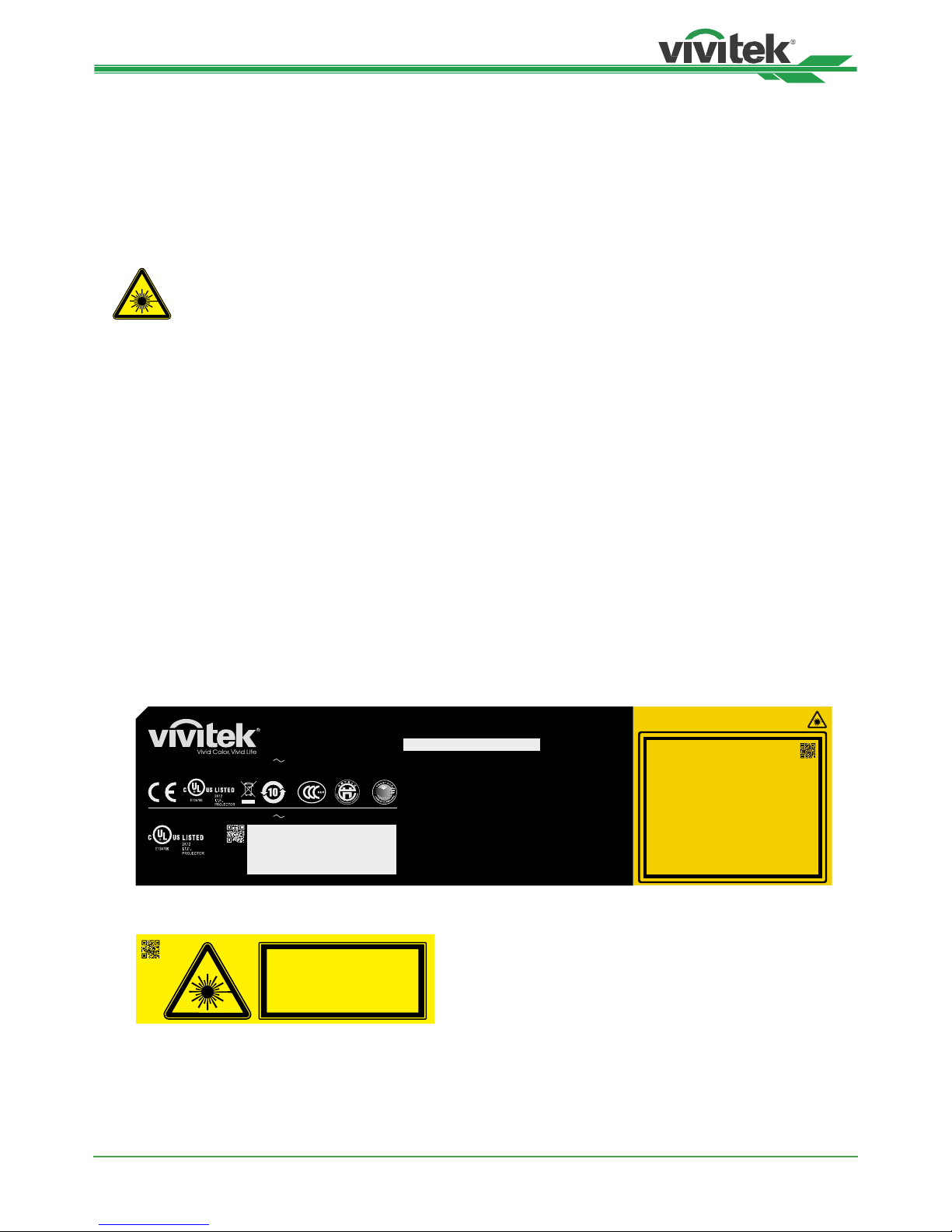
Product Label
Manufacturer’s ID Label, Explanatory Label and Certication Statement Label
AC INPUT/Entrée CA
(
輸入/Ꮾˢ
) :
100-130 VAC 9.5A 50/60Hz
AC INPUT/Entrée CA
(
輸入/Ꮾˢ
) :
200-240 VAC 4.5A 50/60Hz
DLP Projector / Projecteur DLP
(
㕟ἴ㉼⽘㩆
ᇴфԸᇆ፟
)
Model/Modèle/
(
型號/ݭཱི
) :
This device complies with part 15 of the FCC rules.
Operation is subject to the following two conditions:
(1) this device may not cause harmful interference, and
(2) this device must accept any interference received,
including interference that may cause undesired operation.
CAN ICES-3(A) /NMB-3(A)
Caution : Do not open the cover. No user-serviceable parts inside
Avertissement : ne pas ouvrir le couvercle. Le produit ne contient
aucune pièce interne réparable par l’utilisateur.
娤⌈妉↽ㄑ摉⟔㩺士ὗ‥㿟㗋↗⻥䱫Ậᴉ ᶴ
ᛋ!!Ә!!;!ኛχฟγഥ-న౯ڇચّჯ࣒І
娤⌈ḽ䏦仃㨢᳸$䵥ᵥ⍿濕◦䏝㯹䉭❁ᳫ濕媣ᵥ⍿⊭侻廞ノ㒞䵽䏳ⴰㄮƲ
◦店䢋⾃濕⊭侻斾堿䏦ヵ⪷ⴰㄮ悅⊔⩜⊭圊䕂㉨㑻Ʋ
娤⌈ḽ䏦仃濣㨢㽸䏰朜宅壈ㄾ圑士ὗ濕㑺⬃ḍ䍮❁ᳫḽ䏦濕⊭侻㗁廞ノ⫂曹㎼↓濕
◦㨢ᳫ⾃㭿濕ḽ䏦仃㗁坩堿㬀㉟⊔㚎ᵙ弧䐴䕂⫋䨔Ʋ
∝怇┭⏗徥䔜⬷Ứḁ䮈䏭Ƌ㵞ƌ㛰昷⅓⏟
0DGHLQ&KLQD壤怇✗Ḕ⛲Ḕ⛤
:-;;;;
Complies with FDA performance standards for laser
p roducts except for deviations pursuant to Laser
Notice No. 50, dated June 24, 2007
LASER RADIATION
AVOID DIRECT EYE EXPOSURE
CLASS 3R LASER PRODUCT
Emitted wavelength : 450-460 nm
Max. Pulse energy: 0.376 mJ, Pulse duration: 0.74 ms
㹾 幎⫂弽䗺䘙⊕䖲㉣䀥⫂3R䬹㹾 ᵥ⍿
㮠搽
: 450-460 nm
㖾⟥俇⁰侻悍: 0.376 mJ俇⁰㒴撲: 0.74 ms
㹾 巹⫂弽䗺䘙⊕䖲㉣䀥⫂3R朜㹾 䏠⍿
㮠搵: 450-460 nm
㖾⟥俆圛侻悍: 0.376 mJ俆圛㔀摑: 0.74 ms
RAYONNEMENT LASER
EXPOSITION DIRECTE DANGEREUSE POUR LES YEUX
APPAREIL À LASER DE CLASSE 3R
longueur d'onde : 450-460nm
maximum énergie de impulsion : 0.376 mJ,
durée de impulsion : 0.74 ms
GB 7247.1-2012 / IEC/EN 60825-1:2007
CLASS 1 LASER PRODUCT
IEC/EN 60825-1:2014
PRODUIT LASER DE CLASSE 1
IEC/EN 60825-1:2014
3264638203
Hazard Warning Symbol and Aperture Label
3262162601
LASER APERTURE
斵⫂巹⫂ᴉ⨒⹏
㹾 幎⫂䥕⊡
OUVERTURE LASER
Page 6

DK8500Z-BK DLP Projector - User Manual
UM8500217EN00
6
Installation and Use Notices
1. Read and keep this manual properly.
2. Pay attention to all the noted warnings, and follow all the guidelines and descriptions in this manual.
3. Do not use the projector near water.
4. Do not install the equipment near the thermal sources, such as heaters, radiators, furnace, ampliers, and any
other equipment that may generate heat.
5. Be careful while holding the equipment or moving the trolley with projector to prevent the equipment from turning
over.
6. Notice whether there is any parts with aws after receiving the projector.
7. Please notice that the projector will not power on until the lens is tted. The protection covering the lens should
be taken to install the lens.
8. Do not let any vent be obstructed.
9. Do not destroy the safety protection function of polarized or grounding plug of power cord. A polarized plug
has one wide and one narrow blade. The plug has two blades and one grounding blade. The wide blade or
grounding blade is provided for the safety concerns. If the plug provided does not match the outlet, please
contact the electrician to change outlet.
10. The +12V trigger only outputs 12V DC trigger signal. Do not connect other power input or output. Otherwise, the
equipment may malfunction.
11. Adjust the slide switch with suitable volt input, and then plug in the projector; the red LED indicator would ash
and then stabilize, getting into standby mode. User should only use the connectors or accessories provided by
the manufacturer.
12. When user turns on the projector, the red LED indicator would ash until stabilize. Do not look at the lens directly
while the projector is running.
13. Unplug the power cord of the equipment if there is a thunderstorm or the equipment is not going to be used for a
long time.
14. The packaging materials can be kept properly for transportation use afterwards.
15. If any breakdown occurs, please contact dealer or manufacture for qualied repair service.
RG2
CAUTION: Do not look into the lens
Disposal of Old Electric and Electronic Equipment
The symbol on your product or the package represents that the product should not be treated as the normal
household waste when discarded but should be carried to the recycling location of the waste electric and electronic
equipment. The consequence on the environment and human health due to the incorrect disposal of the product can
be prevented if it can be ensured that the product is properly discarded. Material recycling is helpful to the protection
of natural resources. The symbol is only valid in European Union. If you want to discard electrical and electronic
equipment, contact the governmental authorities or your dealer for the correct method of disposal.
Important Recycling Instructions
The product may contain other electronic wastes and may pose risk if not discarded properly. Abide by the local,
state/provincial or federal laws of recycling or discarding. For more information, please visit the website and contact
Electronic Industries Alliance (EIA) on WWW.EIAE.ORG.
Page 7
DK8500Z-BK DLP Projector - User Manual
UM8500217EN00
7
Introduction
The User’s Manual describes the installation, setup and operation of the DK8500Z projector and provides assistance
to the installation personnel and the end-user to fully develop the performance of the projector. VIVITEK has made
every effort to ensure that the information in the Manual is correct at the time of printing. The contents may be
frequently updated due to the continuously product improvement and customer feedback.
You can nd the latest version of the Manual and the manual of other Vivitek products on www.vivitekcorp.com.
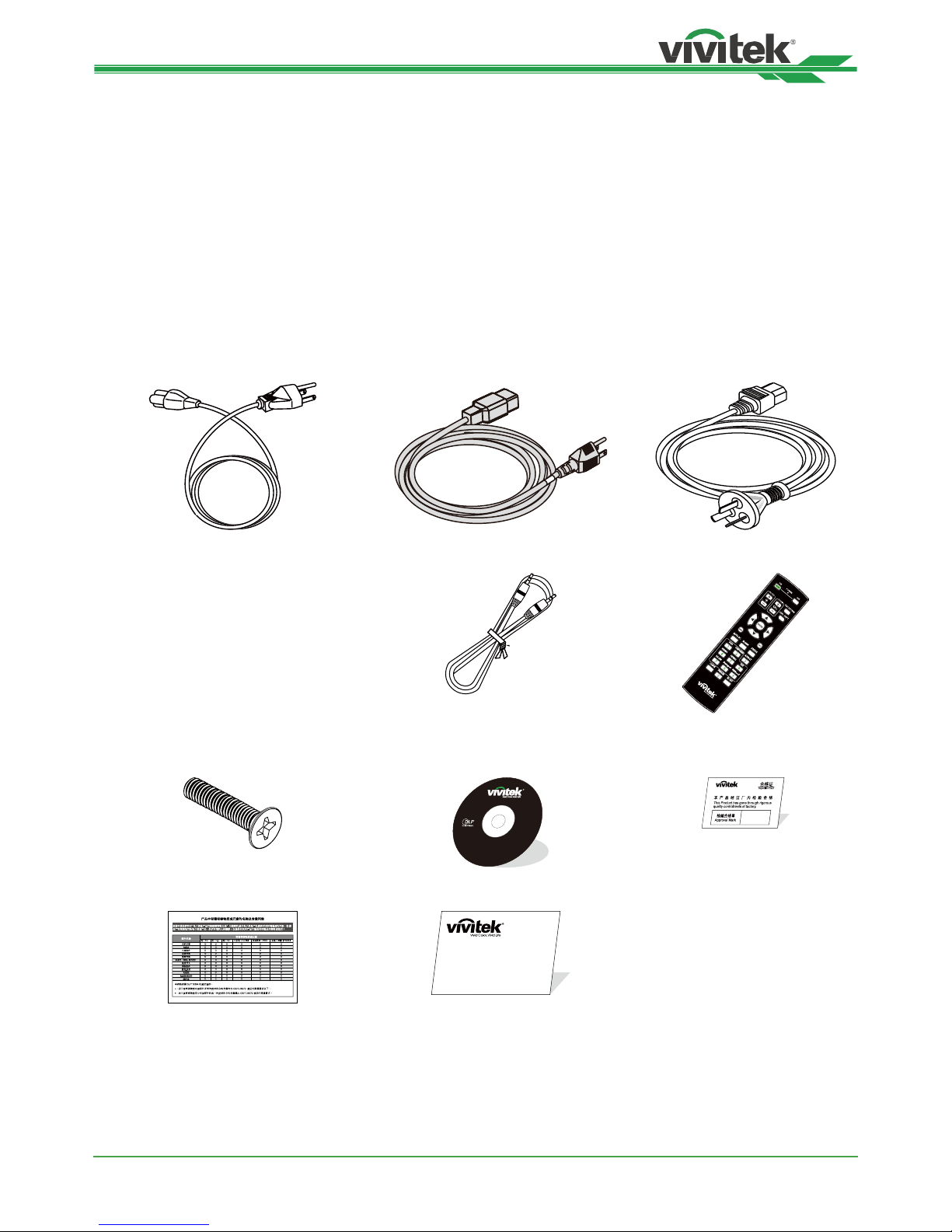
Packing Checklist
The following items are included in the packaging box of the DK8500Z projector. If any loss or damage to any item,
contact your dealer or Vivitek customer service department.
Power Cord-USA Power Cord-EU Power Cord-China
HDMI Signal Cable Wired Remote Cable IR Remote Control
Anti-thief Screw (M4)
(for Lens Installation) User’s Manual Disc Certicate (China)
RoHS Card(China) Limited Warranty
Page 8
DK8500Z-BK DLP Projector - User Manual
UM8500217EN00
8
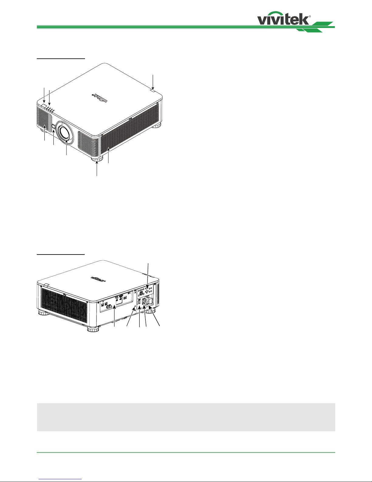
Projector Overview
Front-right View
1
2
8
7
4
5
6
3
1. Front IR Receiver
The Receiver for IR signals from remote control.
2. LED Indicator
Display current projector status such as power, light source
status and warning.
3. Air Intake
The fan pulls the cool air to the projector for system
cooling.
4. Lens Release Button
Press the Lens Release button before removing the lens.
5. Lens hood
Remove the cover before installing the lens.
6. Height Adjuster
Adjust level of projector
7. Intake Vent
The fans pull air to cool the radiator of the projector.
8. Rear IR Receiver
The Receiver for IR signals from remote control.
Rear-right View
14
91112
13
10
9. I/O Connector Panel
Connect to various input, control or output terminals to the
projector.
10. Kensington Lock
Attach the projector to a permanent object with the
Kensington slot and a security cable.
11. Slide Switch
Switch it to corresponding input voltage
12. AC Power Switch
Turn on/off the AC power of the projector.
13. AC Inlet
Connect the supplied power cable to this inlet.
14. Control Panel
Press the button to operate the OSD menu or adjust the
lens Settings see OSD controls.
Important:
The air passes through grill openings on the projector is for good air circulation. Do not obstruct any of the grill
openings and keep the required distance from any object.
Page 9
DK8500Z-BK DLP Projector - User Manual
UM8500217EN00
9
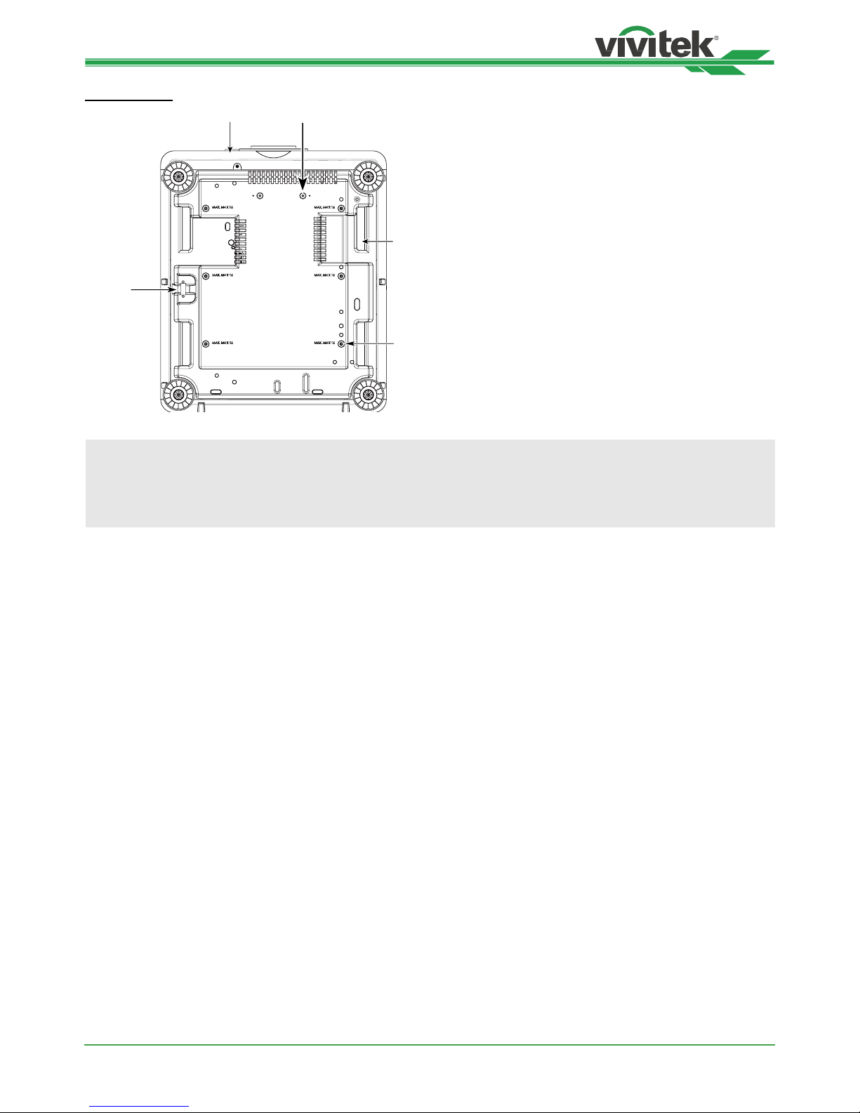
Bottom View
15
16
19
17
18
15. Anti-thief Screw hole
The anti-thief screw can be fastened to prevent
Lens removing by unauthorized person.
16. Mounting Holes of Support Kit
These two screws holes can be used to x support
kits of ultra-short throw lens.
Note: The screws are for Lens support kits only;
overloading may damage the projector or cause
injury.
17. Recess for projector handling.
These four recesses can be used for handling the
projector.
18. Ceiling Mounting Hole
Total 6 holes for M4 screw, maximum depth 14mm.
19. Security Slot
The slot can be used for Short-term protection
Note:
• When installing, ensure that you use only UL Listed ceiling mounts, Contact your dealer for information on
mounting the projector on a ceiling.
• With ceiling installation, use approved mounting hardware & M4 screws; maximum depth of screw: 14 mm.
Page 10

DK8500Z-BK DLP Projector - User Manual
UM8500217EN00
10
HDMI1HDMI
2
HDBaseT / LAN Ethernet
DisplayPort
RS232
WIRED REMOTE
SDI IN SDI OUT
TRIGGER
1 2
IO Panel
TRIGGER(12V +/-1.5V)
When connected to the screen through a 3.5mm cable, the
screen deploys automatically on startup of the projector.
The screen reacts when the projector is powered off.
RS-232
The 9-pin D-sub interface is used to connect to the PC
control system and projector maintenance.
WIRED REMOTE
Connect the supplied remote controller to the projector
HDBaseT/LAN
Connect an Ethernet cable (Cat5e/Cat6, not supplied)
from a computer, network device, or HDBaseT
transmitter.
Ethernet
Connect an Ethernet cable (Cat5e/Cat6, not supplied)
from a computer, network device not to support HDBaseT
HDMI 1 / HDMI 2
Connect the HDMI cable from a computer or video device
SDI IN/OUT
Connect to SDI source.
DisplayPort
Connect a video source to projector
Note for Trigger
• When the projector is turned on, a control signal (DC 12V) outputs from this terminal.
• Do not use this jack for anything other than intended use.
Note for Wired Remote
• Please make sure whether the port for insertion is correct before the terminal of the wired remote control is
inserted. The remote control may be damaged if inserted to the wrong port such as trigger. Do not use this jack
for anything other than intended use.
Page 11
DK8500Z-BK DLP Projector - User Manual
UM8500217EN00
11
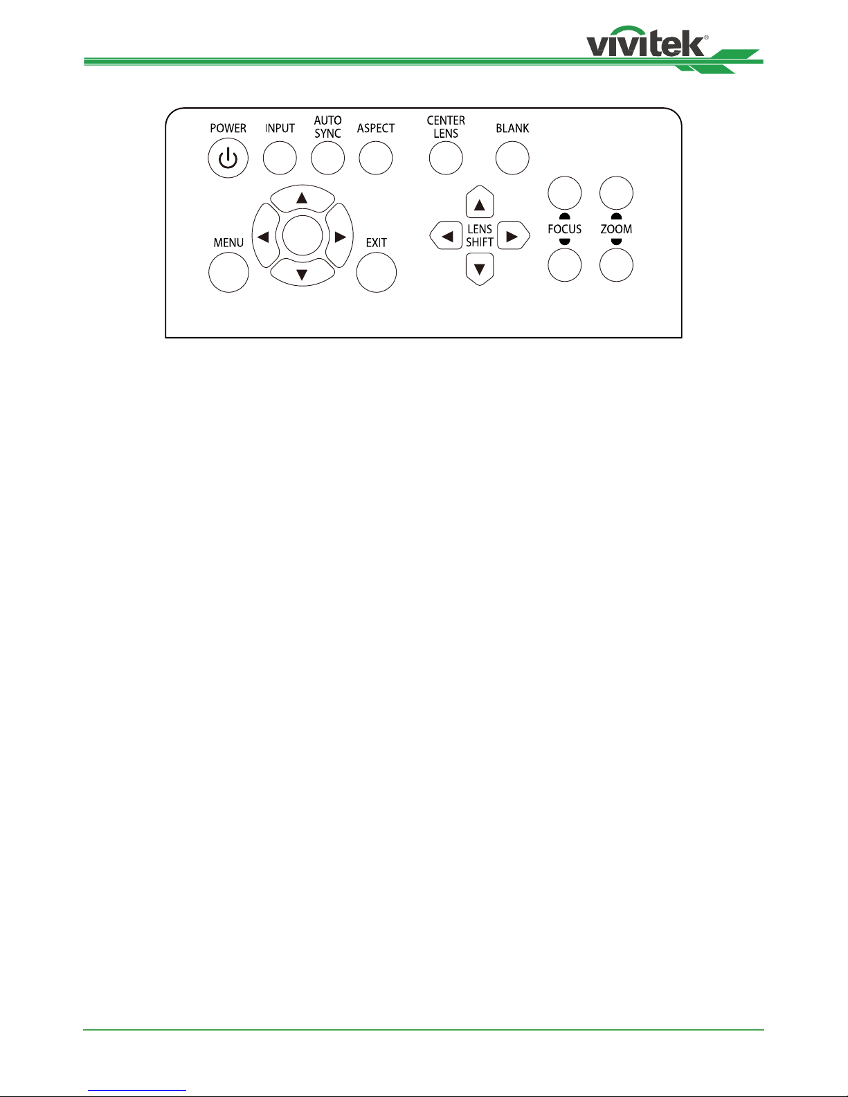
Control Panel
ENGER
++
--
POWER
User the button to turn on/off the projector.
INPUT
Push the button to select the input signal. HDMI, DVI,
VGA, Component…etc.
AUTO SYNC
Implement automatic signal synchronization.
ASPECT
Change the aspect ratio of the current image and push
the button to change to the next aspect ratio settings.
MENU
Push the button to display or hide the OSD menu.
UP/Down/Left/Right
Use the button to select the OSD option.
ENTER
Use the button to select settings or conrm the changed
settings.
EXIT
Push the button to return to the menu on the previous
level or exit the OSD menu.
CENTER LENS
Push the button to center the lens and calibrate the
parameter of lens shift, focusing and zooming.
Note: The lens memory function requires the accurate
lens adjustment parameter. Please center the lens every
time after the lens is mounted.
Blank
Use the button to stop the projection temporarily
LENS SHIFT
Use these four buttons to move the projected image to
desired position.
FOCUS
Use the button to adjust the focus of projected image.
ZOOM
Use the button to zoom in/out the projected image.
Page 12
DK8500Z-BK DLP Projector - User Manual
UM8500217EN00
12
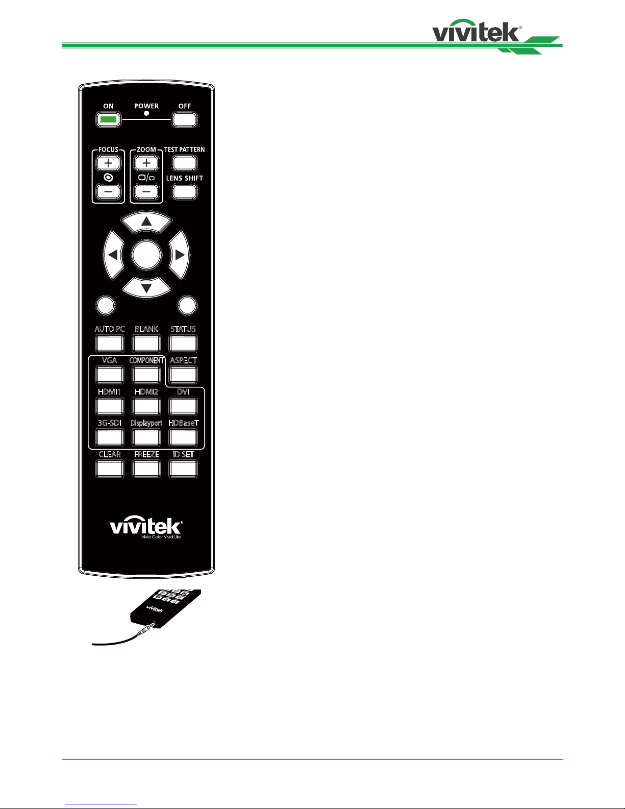
Remote Control
MENU
EXIT
ENTER
1
4
7
0
89
6
3
5
2
HDMI1 HDMI2 DVI
CLEAR FREEZE ID SET
3G-SDI
Displayport
HDBaseT
VGA ASPECT
COMPONENT
AUTO PC BLANK STATUS
On
Use the button to turn on the projector.
OFF
Use the button to turn off the projector.
FOCUS
Adjust the focus of the projected image.
ZOOM
Zoom in/out the projected image.
TEST PATTERN
Use the button to show the test pattern. Press this button again to switch to
the next pattern. Press the EXIT button to return to the projected image.
LENS SHIFT
Use the button to move the lens right or left.
ENTER
Use the button to select settings or conrm the changed settings.
MENU
Press the button to display or hide the OSD Menu.
EXIT
Press the button to return to the previous Menu or exit the OSD Menu.
AUTO PC
You can use this function to execute signal source auto synchronization
BLANK
Press the button to temporarily interrupt the projection.
STATUS
Show OSD MENU – SERVICE.
VGA
Select VGA input source. (not applicable for DK8500Z-BK)
COMPONENT
Select Component input source.
ASPECT
Press the button to display aspect ratio options.
HDMI1
Select HDMI 1 input source.
HDMI2
Select HDMI 2 input source.
DVI
Select DVI input source.
3G-SDI
Select 3G-SDI input source.
DisplayPort
Select DisplayPort input source.
HDBaseT
Select HDBaseT input source.
CLEAR
Erase the set ID number of the remote control; refer to the section “Using
Control ID for Multi-projector Application” on page 26.
FREEZE
Freeze the projected image or resume the projection.
ID SET
Set up ID number for remote control; refer to the section “Using Control ID
for Multi-projector Application” on page 26.
Wired Remote Jack
Connect to WIRED REMOTE terminal
on the projector
Page 13
DK8500Z-BK DLP Projector - User Manual
UM8500217EN00
13
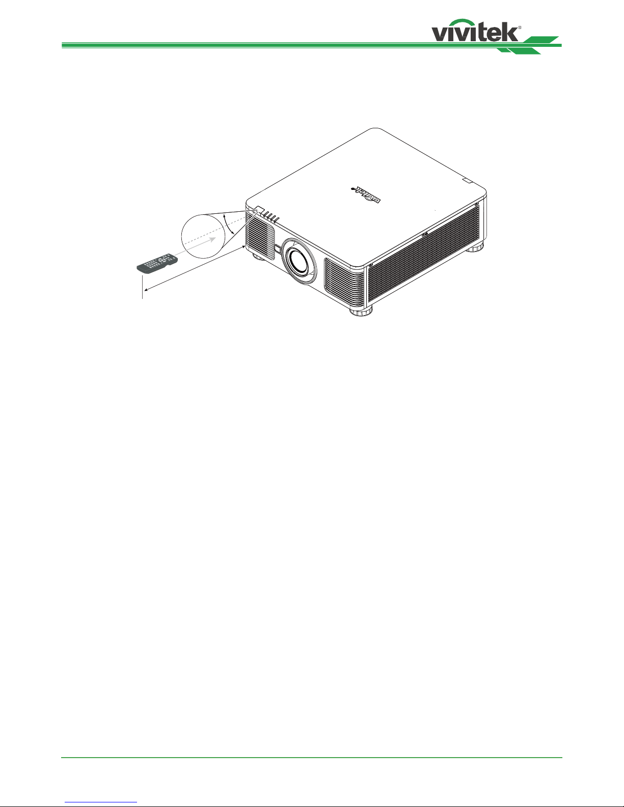
Remote Control Operating Range
The remote control uses infrared transmission to control the projector. It is not necessary to point the remote directly
at the projector. Provided you are not holding the remote perpendicular to the sides or the rear of the projector, the
remote will function well within a radius of about 10 meters (25 feet) and 15 degrees above or below the projector
level. If the projector does not respond to the remote control, move a little closer.
10m
±30°
Page 14
DK8500Z-BK DLP Projector - User Manual
UM8500217EN00
14
Installation and Setting up
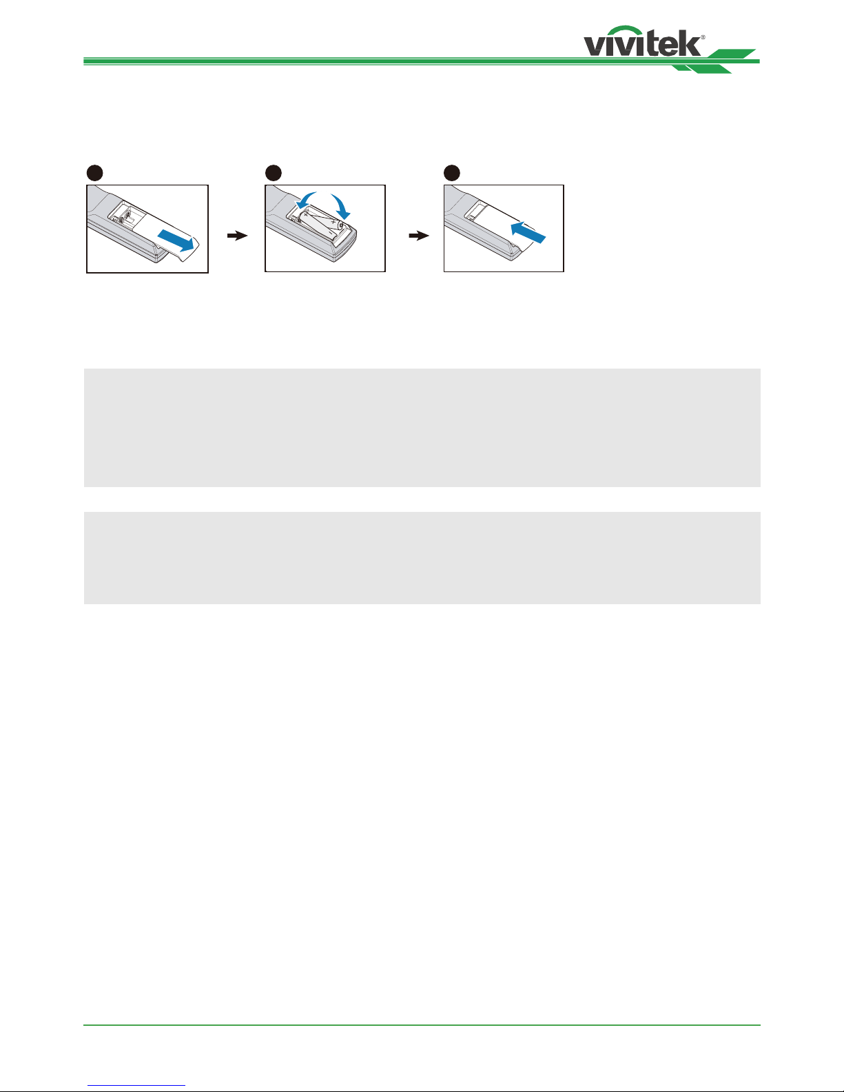
Inserting or Changing the Remote Control Batteries
1
2
3
1. Remove the battery compartment cover by sliding the cover in the direction of the arrow.
2. Place two AA batteries with the correct polarity.
3. Slide on the cover as the arrow in the illustration.
Important:
• Avoid using the projector with bright uorescent lighting turned on. Certain high-frequency uorescent lights can
disrupt remote control operation.
• Be sure nothing obstructs the path between the remote control and the projector.
• Do not expose the remote control to high temperature or humidity; otherwise, the remote control will not work
functionally.
Battery installation instructions
• Make sure the battery is installed with the correct polarity
• Do not use the old and new batteries or the batteries of different types together
• Remove the battery if the remote control may not be used for a long time to prevent the damage caused by
leaks.
Page 15
DK8500Z-BK DLP Projector - User Manual
UM8500217EN00
15
Installing the projector
The high quality display effect can be guaranteed only when the projector is correctly installed. Generally, the light
source facing the screen should be reduced or eliminated as much as possible. The contrast of the image will be
obviously reduced if the light directly shines on the screen, such as the beam from windows or the searchlight cast on
the image. The image may become faded and not bright.
Precautions for Installation
Caution:
• Projector installation must be done by a qualied professional. Contact your dealer for more information. It is not
recommended you install the projector yourself.
• With ceiling installation, use approved mounting hardware & M4 screws; maximum depth of screw: 14 mm.
Contact your dealer for information about mounting the projector on a ceiling.
• Only use the projector on a solid, level surface, serious injury and damage can occur if the projector is dropped.
Caution:
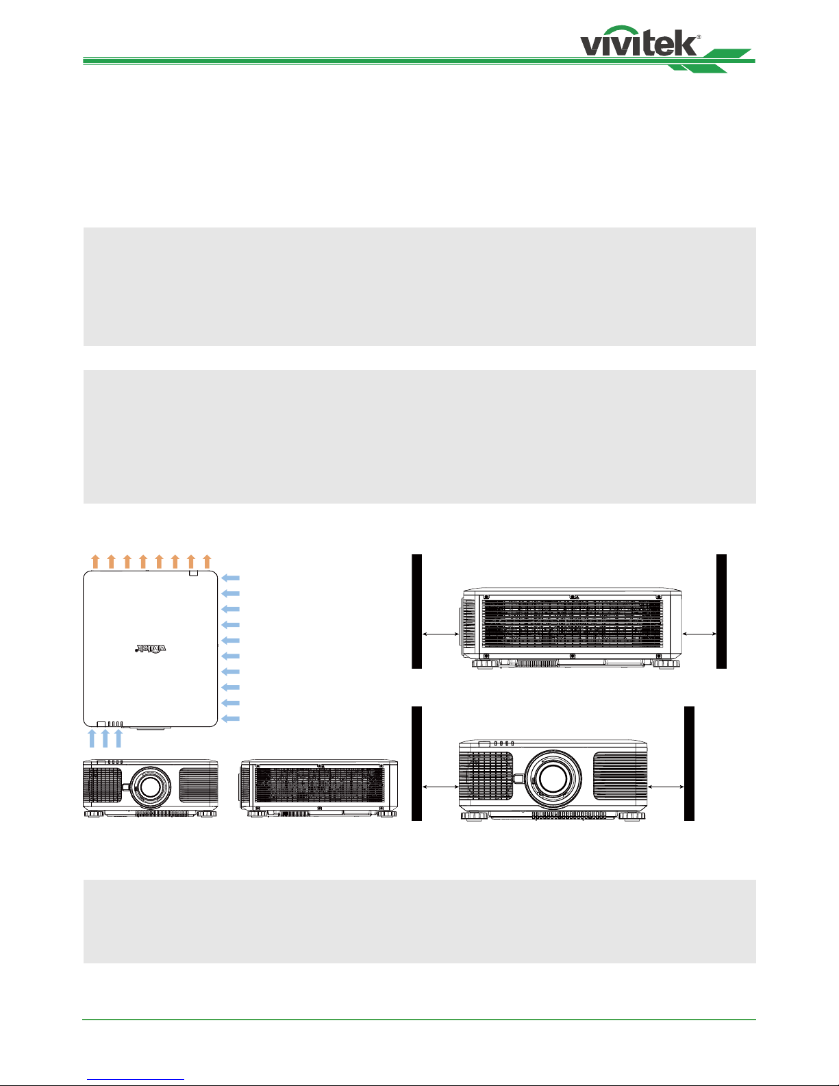
• Ensure that the hot air from the exhaust vent is not sucked into the projector.
• Ensure the air intake and exhaust vents are unobstructed and keep the required distance from any object.
Below is required minimum distance between the vent and any object.
• All added enclosures should pass a certied thermal evaluation to ensure that the projector does not recycle
exhaust air, as this may cause the projector to shut down even if the enclosure temperature is with the
acceptable operation temperature range.
Airow and Heat Emission Minimum Distance to Vent
POWER
STATUS
LIGHT
TEMP.
50cm
50cm
50cm 50cm
Caution:
• Only use the projector on a solid, level surface, serious injury and damage can occur if the projector is dropped.
• Please do not stack the projector on the surface of another projector, serious injury and damage may occur if
the projector is dropped
Page 16

DK8500Z-BK DLP Projector - User Manual
UM8500217EN00
16
Mounting the projector
For mounting the projector, please use UL Listed ceiling mounts and M4 screws, maximum depth of screw: 14 mm.
Page 17

DK8500Z-BK DLP Projector - User Manual
UM8500217EN00
17
Installing or Removing the Optional Lens
Caution:
• Do not shake or place excessive pressure on the projector or the lens components as the projector and lens
components contain precision parts.
• When shipping the projector with the optional lens, remove the optional lens before shipping the projector. The
lens and the lens shift mechanism may encounter damage caused by improper handling during transportation.
• Before removing or installing the lens, be sure to turn off the projector and wait till the cooling fans stop, and turn
off the main power switch.
• Do not touch the lens surface when removing or installing the lens.
• Keep ngerprints, dust or oil off the lens surface. Do not scratch the lens surface.
• Work on a level surface with a soft cloth under it to avoid scratching.
• If you remove and store the lens, attach the lens cap to the projector to keep off dust and dirt.
Install New Lens
1. If the Lens cover is installed, pull the edge of the lens cover with one hand ( ), so that the lens cover can be
removed easily with the other hand ( )
2
1
2. Align the “ “ symbol on the lens label with the “ * “ symbol on the top of the body (align to the center of the lens
hole) and pull in the lens.
Arrow up
3. Make sure the lens is pushed into the holder and turn it clockwise to the “Lock” position. When turning the lens,
the “Click” sounds twice to indicate that the lens is completely xed.
4. Check if the lens is xed successfully by pulling the lens out of the holder gently.
Page 18
DK8500Z-BK DLP Projector - User Manual
UM8500217EN00
18
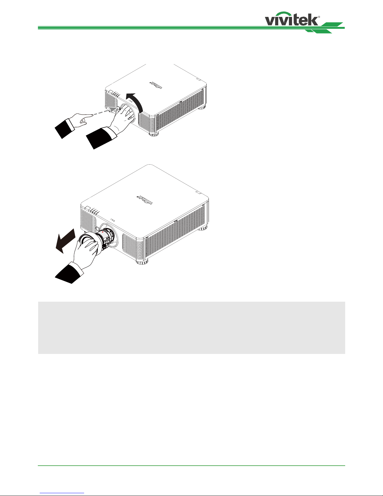
Removing the Existing Lens
1. Push the LENS RELEASE button all the way in and rotate the lens counterclockwise. The existing lens will be
disengaged
2. Pull out the existing lens slowly.
Caution:
• When installing the lens into the projector, be sure to remove the lens cap from the back of the optional lens
before installing the optional lens into the projector. Failure to do so will cause damage to the projector and lens.
• There is one safety switch inside the lens slot on the projector to prevent unexpected injury by laser beam, the
projector cannot be turned on if the projection lens has not been installed or is not installed correctly. Please
make sure the lens is installed properly before tuning on the projector.
Page 19
DK8500Z-BK DLP Projector - User Manual
UM8500217EN00
19
Selecting the Input Voltage of AC Power
There is one slide switch near AC switch, pleases switch it to corresponding input voltage of AC power. Please switch
it to 115V if the input voltage range is 100V to 130V, switch to 230V if input voltage range is 200V to 240V.
VOLTAGE SELECT
Ϲ߹ᑅᏴፄ
200~240 VAC
100~130 VAC
230
Connecting to AC Power Supply
The AC power cord is included in the box; plug the power cord to the AC socket on the IO panel.
Turning on the Projector
Once the projector is correctly located and the power cable and other connections are in place, it is important that the
projector is correctly powered on in order to avoid damage to components and un-necessary wear and tear. Refer to
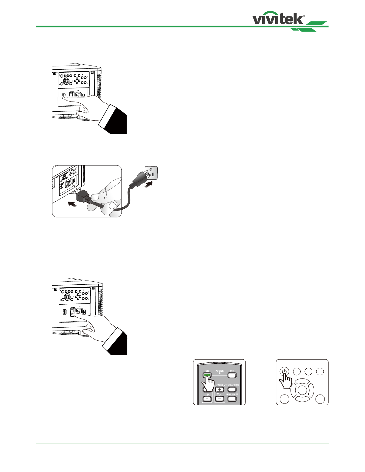
the following guide to power on the projector.
1. Press the main power switch to the on ( I ) position as
shown. POWER LEDs ashes then lights red.
VOLTAGE SELECT
Ҭࢬႝᓸᒧ
200~240 VAC
100~130 VAC
230
2. Press the POWER button on the control panel or ON
button on the remote control.
MENU EXIT
POWER
INPUT
AUTO
SYNC ASPECT
Page 20
DK8500Z-BK DLP Projector - User Manual
UM8500217EN00
20
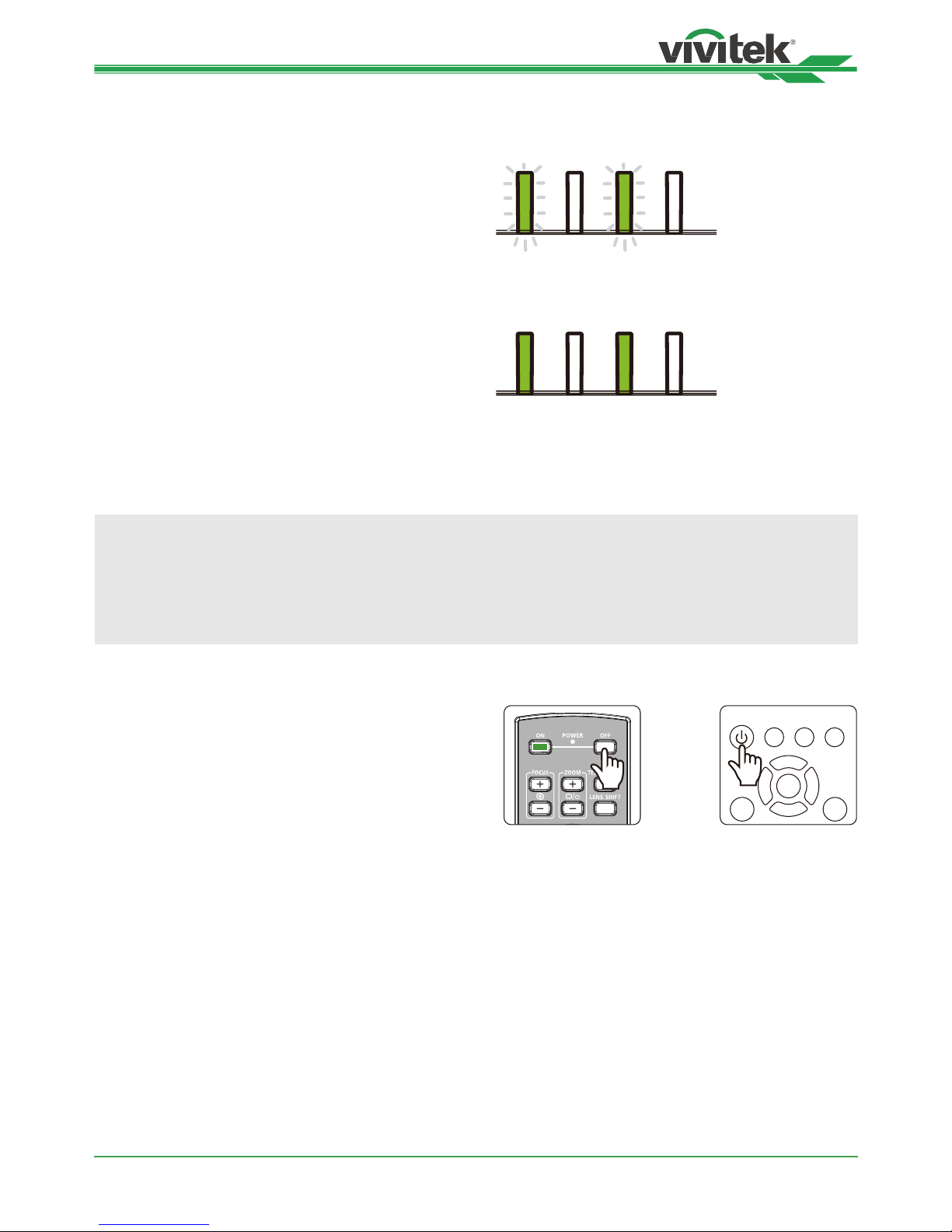
3. The Power LED and LIGHT LED ashes green till power
on process is nished.
POWER
STATUS
LIGHT
TEMP.
4. After few seconds, both LEDs keep green, the projector
is ready for use.
POWER
STATUS
LIGHT
TEMP.
Turning off the Projector
Once the projector is no longer required, it is important to shut it down correctly to avoid damage or unnecessary wear
and tear to the projector.
Note:
• Do not unplug the power cable from the wall outlet or projector when the projector is powered on. Doing so can
cause damage to the AC IN connector of the project or the prong plug of the power cable. To turn off the AC
power supply when the projector is powered on, use a power strip equipped with a switch and a breaker.
• Do not turn off the AC power supply within 10 seconds after making adjustment or changing the setting. Doing
so is possible to cause loss of adjustments and settings and return to default.
Refer to the following guide to shut down the projector.
1. Press the POWER button on the control panel or OFF
button on the remote control once, the Power Off
window displays.
MENU EXIT
POWER
INPUT
AUTO
SYNC ASPECT
2. Press the POWER button again on the OSD control
panel or remote control to verify power off, the power
LED ashes orange after Power Off is conrmed.
3. The projector enters SAVING mode when the power
LED lights red.
4. Press the Main Power switch to the off position (O) to
turn off the projector.
Page 21
DK8500Z-BK DLP Projector - User Manual
UM8500217EN00
21
Setting up the installation condition
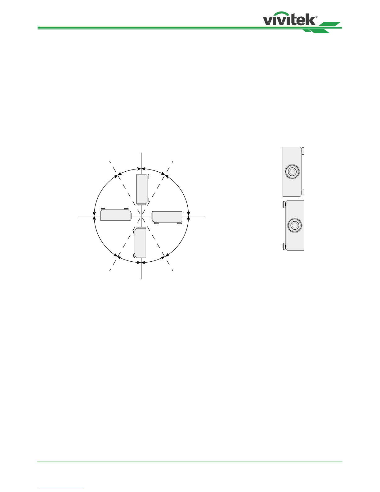
DK8500Z is designed for set up in all angle including desktop, ceiling, portrait and free-tilt installation as below
illustration. Please set the cooling condition according to the projector installation as below.
Desktop: Install the projector on the table for front projection or rear projection.
Ceiling: Mount the projection on the ceiling for front projection or rear projection
Freetilt: Install the projector at an angle, the angle is over ±60ºC
Portrait: Install the projector at an angle 90° to project the portrait image.
Auto: The projector is equipped with orientation sensor; projector switches the cooling condition by detected projector
orientation.
Desktop, Ceiling and Free-tilt Installation
30°
60°
60°60°
60°
30°
30°
30°
Free-tilt
Free-tilt
Ceiling Desktop
Portrait Installation
Setting up the Projection Mode
The projection mode option can be used to change the orientation of the projected image or ip the projected image.
Front Desktop: Install the projector on the table and project the image on the screen forward.
Front Ceiling: Mount the projector on the ceiling and project the image on the screen forward, the image is
overturned.
Rear Desktop: Install the projector on the table and project the image from the rear of the screen.
Rear Ceiling: Mount the projector on the ceiling and project the image from the rear of the screen, the image is
overturned.
Page 22
DK8500Z-BK DLP Projector - User Manual
UM8500217EN00
22
Adjusting Projected Image Position
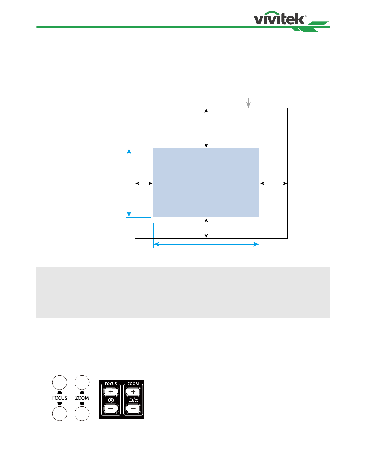
The DK8500Z projector has the powered lens shift feature; the image can be shifted vertically or horizontally without
moving the projector. The lens shift range is shown in the percentage of the screen height and width, the maximum
vertical shift range can be up to 64% of the projected image height and down to 33% of the height, and maximum
horizontal shift range is 24% of the image width to right, 14% of the image width to the left. Please refer to below
illustration.
The bounday of Lens shift
V: Projected Image
Height
H: Projected Image Width
64%
33%
14% 24%
Note:
• The projector is equipped with safety switch inside the lens mount hole; the projection lens must be installed in
the projector before turning on the power. Or the projection can’t be started.
• There is a Lens Lock function on OSD menu to disable lens control adjustment for avoiding possible
misoperation after you nish the adjustment, please make sure to disable the lock before performing the lens
control.
Adjusting the Focus and Zoom
The focus and zoom can be adjusted from the projector control panel or remote control. Refer to the following guides
to adjust the focus and zoom manually.
Press the Focus or Zoom button on the control key panel or remote control to adjust the focus or zoom effect using
the increase and decrease buttons as required
++
--
Page 23
DK8500Z-BK DLP Projector - User Manual
UM8500217EN00
23
Preventing the Unauthorized Use of the Projector
Using the Control Panel Lock
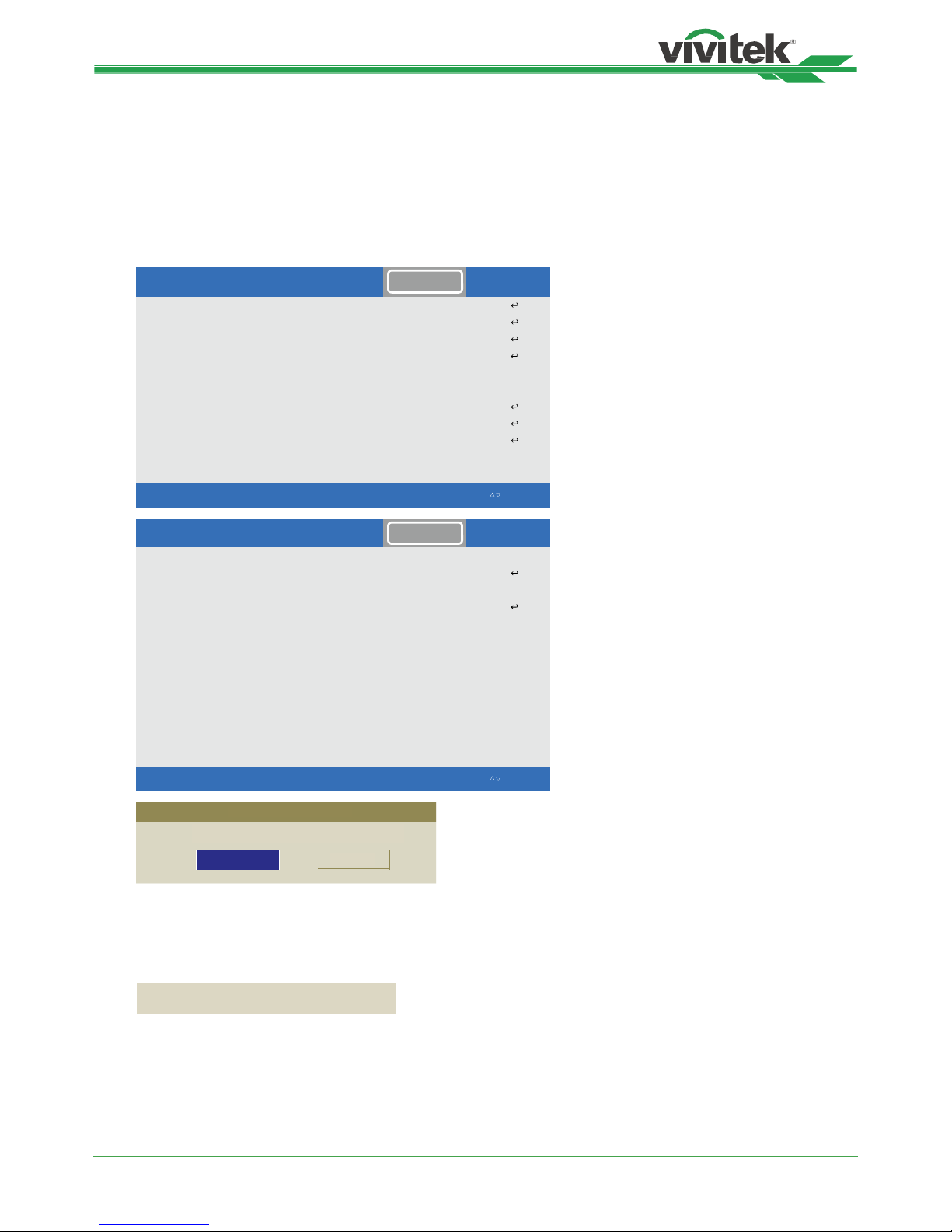
This function allows you to lock control panel on the projector for preventing the unauthorized operation on control
button.
Locking the control buttons
Select CONTROL>OSD Settings>Control Panel Lock to enable the function as below illustration.
Language
Projection Mode
High Altitude Auto
Standby Mode Saving
Auto Power Off <Off >
Auto Power On <Off >
Network
Light Power
Backgroun
dB
lack
Startup Logo <On>
ˑ
INPUTPICTURE ALIGNMENT CONTROL SERVICE
EXIT = Back Item Adjust ◄► Scroll Ⴃ
Ⴍ
炾►
炾►
炾►
炾►
炾►
炾►
Front Desktop
炾►
INPUTPICTURE ALIGNMENT CONTROL SERVICE
ˏ
Infrared Remote
>ffO<reggirT
OSD Settings
炾►
炾►
EXIT = Back Item Adjust ◄► Scroll Ⴃ
Ⴍ
Control Panel Lock
Ok Cancel
Control Panel Lock will be turned on, sure?
The pop-up message will be shown as above if Control Panel Lock is turned on, select OK to conrm or Cancel to
ignore the setting.
Once Control Panel Lock is enabled, all of control buttons on the projector are locked. Below message is shown on
the screen few seconds if any control buttons is pressed.
Control Panel Lock is turned on
Page 24

DK8500Z-BK DLP Projector - User Manual
UM8500217EN00
24
Unlocking the control panel
Once Control Panel Lock is enabled, all of control buttons on the projector are disabled. Please enter the OSD option
CONTROL>OSDSettings>Control Panel Lock then select Off to unlock the control panel by remote control.
INPUTPICTURE ALIGNMENT CONTROL SERVICE
ˏ
Infrared Remote
>ffO<reggirT
OSD Settings
炾►
炾►
EXIT = Back Item Adjust ◄► Scroll Ⴃ
Ⴍ
Using Security Lock
This function allows you to lock the projector for preventing the unauthorized turning on the projector; the setting is
valid when you turn on the projector next time.
Enable the Security Lock
Select CONTROL>OSDSettings>Security Lock then select On to enable the function as below illustration.
Language
Projection Mode
High Altitude Auto
Standby Mode Saving
Auto Power Off <Off >
Auto Power On <Off >
Network
Light Power
Backgroun
dB
lack
Startup Logo <On>
ˑ
INPUTPICTURE ALIGNMENT CONTROL SERVICE
EXIT = Back Item Adjust ◄► Scroll Ⴃ
Ⴍ
炾►
炾►
炾►
炾►
炾►
炾►
Front Desktop
炾►
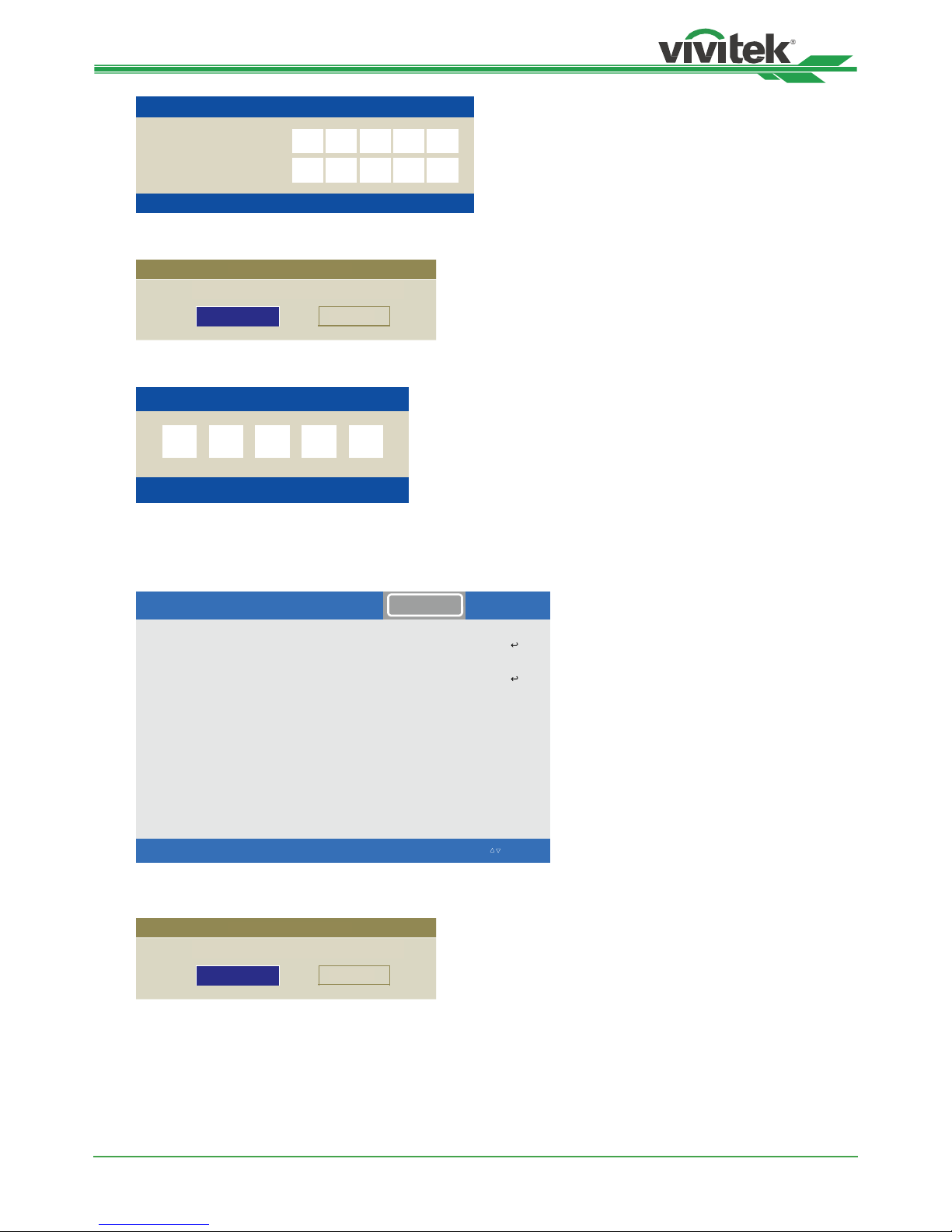
Once Security Lock is turned on, the pop-up message for setting up the password Lock as is shown as below. Press
arrow buttons to set up your password, the password can be the combination of four arrow keys.
Page 25
DK8500Z-BK DLP Projector - User Manual
UM8500217EN00
25
Register Password
Confirm Password
Password
Menu = Cancel
Control Panel Lock is turned on, the pop-up message will be shown Lock as below, select OK to conrm or Cancel to
ignore the setting.
Security Lock
Ok Cancel
Security Lock will be active in next power cycle, sure?
When you turn on the projector next time, the pop-up window will remind you to input the password to start the
projection.
莚
Password
Menu = Cancel
Unlocking the projector
The projector can be unlocked from OSD menu, enter CONTROL>OSDSettings>Security Lock and select Off to
disable Security Lock as below illustration.
INPUTPICTURE ALIGNMENT CONTROL SERVICE
ˏ
Infrared Remote
>ffO<reggirT
OSD Settings
炾►
炾►
EXIT = Back Item Adjust ◄► Scroll Ⴃ
Ⴍ
Once Off option is selected, the pop-up window will be displayed to conrm the setting. Select OK to disable the
function, otherwise select Cancel to ignore the setting.
Security Lock
Ok Cancel
Security Lock password will be cleared, sure?
Page 26
DK8500Z-BK DLP Projector - User Manual
UM8500217EN00
26
Language
Projection Mode
High Altitude Auto
Standby Mode Saving
Auto Power Off <Off >
Auto Power On <Off >
Network
Light Power
Backgroun
dB
lack
Startup Logo <On>
ˑ
INPUTPICTURE ALIGNMENT CONTROL SERVICE
EXIT = Back Item Adjust ◄► Scroll Ⴃ
Ⴍ
炾►
炾►
炾►
炾►
炾►
炾►
Front Desktop
炾►
Using Control ID for Multi-projector Application
When installing more than one projector in the room, the projectors may receive the control signal at the same time.
In this case, you can use control ID function to specify the identication of the projector and remote control to operate
the specied projector. Follow below steps to set up the identication number for the projector and remote control.
Set the Projector identication number
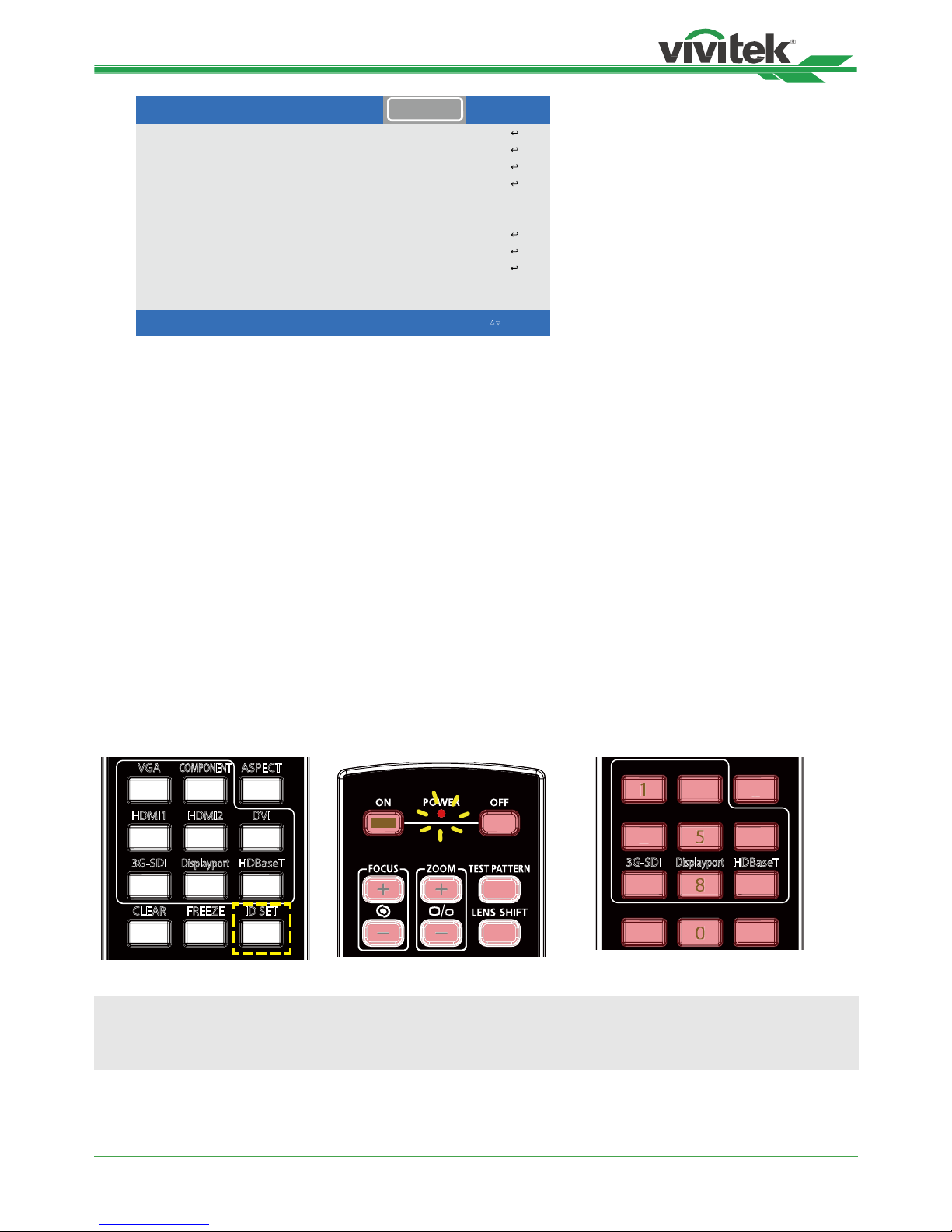
1. Enable Projector ID Control function from CONTROL->Infrared Remote->ID Control Enable as below gure.
The message box is displayed to conrm enabling ID control after selecting ON option, please OK button to
conrm or Cancel button to skip it.
2. Set Control ID Number
Select Control ID Number option then press Enter buttons, use ► button to increase the number or ◄button to
decrease the number to set Projector ID. This option is available when Projector ID Control is turned on.
Set the identication number of remote control
Press and hold ID SET button on the remote control around 5 seconds, Power led indicator is ashing red periodically.
Press two digits to set desired ID number, each digit is saved once Power LED will quickly ash 3 times.
Press and Hold ID SET button
around 5 seconds
Power LED is ashing Press two digits for ID number
1
4
7
0
89
6
3
5
2
HDMI1 HDMI2 DVI
CLEAR FREEZE ID SET
3G-SDI
Displayport
HDBaseT
VGA ASPECT
COMPONENT
HDMI1 HDMI2 DVI
CLEAR FREEZE ID SET
VGA ASPECT
COMPONENT
1
4
79
6
32
9
2
3G-SDI
Displayport
HDBaseT
Note:
• Set the identication number will overwrite the ID number you set, you can set the ID number directly if you
would like to give new ID number for the remote control.
Page 27
DK8500Z-BK DLP Projector - User Manual
UM8500217EN00
27
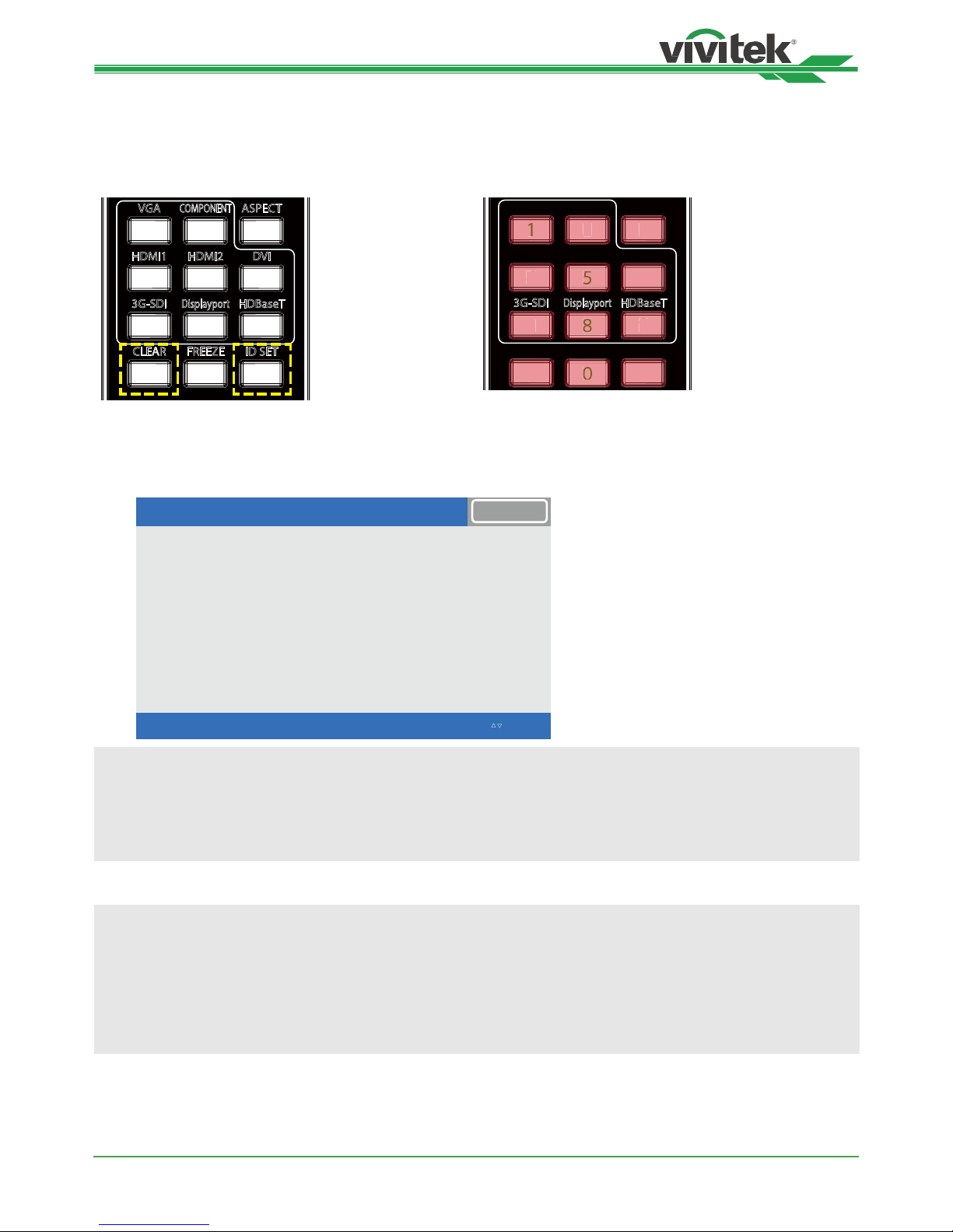
Erase the identication number of the remote control
The set ID number is overwritten if new ID number is set, you can press ID SET and CLEAR button to erase ID
number of the remote control
Press ID SET and CLEAR buttons simultaneously The backlight of the buttons is ashing one time
1
4
7
0
89
6
3
5
2
HDMI1 HDMI2 DVI
CLEAR FREEZE ID SET
3G-SDI
Displayport
HDBaseT
VGA ASPECT
COMPONENT
HDMI1 HDMI2 DVI
CLEAR FREEZE ID SET
VGA ASPECT
COMPONENT
1
4
79
6
32
2
3G-SDI
Displayport
HDBaseT
Checking the identication number of the projector and remote control
The identication number of the projector and remote control can be checked by SERVICE menu as below gure, “X”
represents that the function is not enabled; the number 26 is the current identication number of the remote control.
Model
Serial Number
Software Version 1
Software Version 2
Software Version 3
X / XDI etomeR / lortnoC
Active Source
Signal Format
H/V Refresh Rate
Pixel Clock
ˑ
INPUTPICTURE ALIGNMENTCONTROL SERVICE
EXIT = Back Item Adjust ◄► Scroll Ⴃ
Ⴍ
DK8500Z
WDU80905410010
MD11-VD11-FD09-0.0.3
5
STEP_D08-24-17-3120
HDMI 1
593.60MHz
134.8KHz / 59.9Hz
2.0.8.0-P503
Note:
• Project ID Control function is available when the option is turned on and remote control wire is not plugged into
the wire remote jack.
• If Projector ID Control is set to Off, projector can receive any control signal from the remote control even ID
number is set into the remote control.
Caution:
• When the terminal of the remote control cable is inserted to the wired control terminal of the projector, the
projector will automatically switch to the wired control mode and cannot be controlled through the IR signal of
the remote control. Disconnect the wired control terminal on the projector if you want to control through the IR
signal of the remote control.
• If the wired remote control cable or the external IR transmitter is inserted to the incorrect port, such as Trigger,
the remote control or the IR transmitter may be damaged. Make sure whether the port is correct
Page 28
DK8500Z-BK DLP Projector - User Manual
UM8500217EN00
28
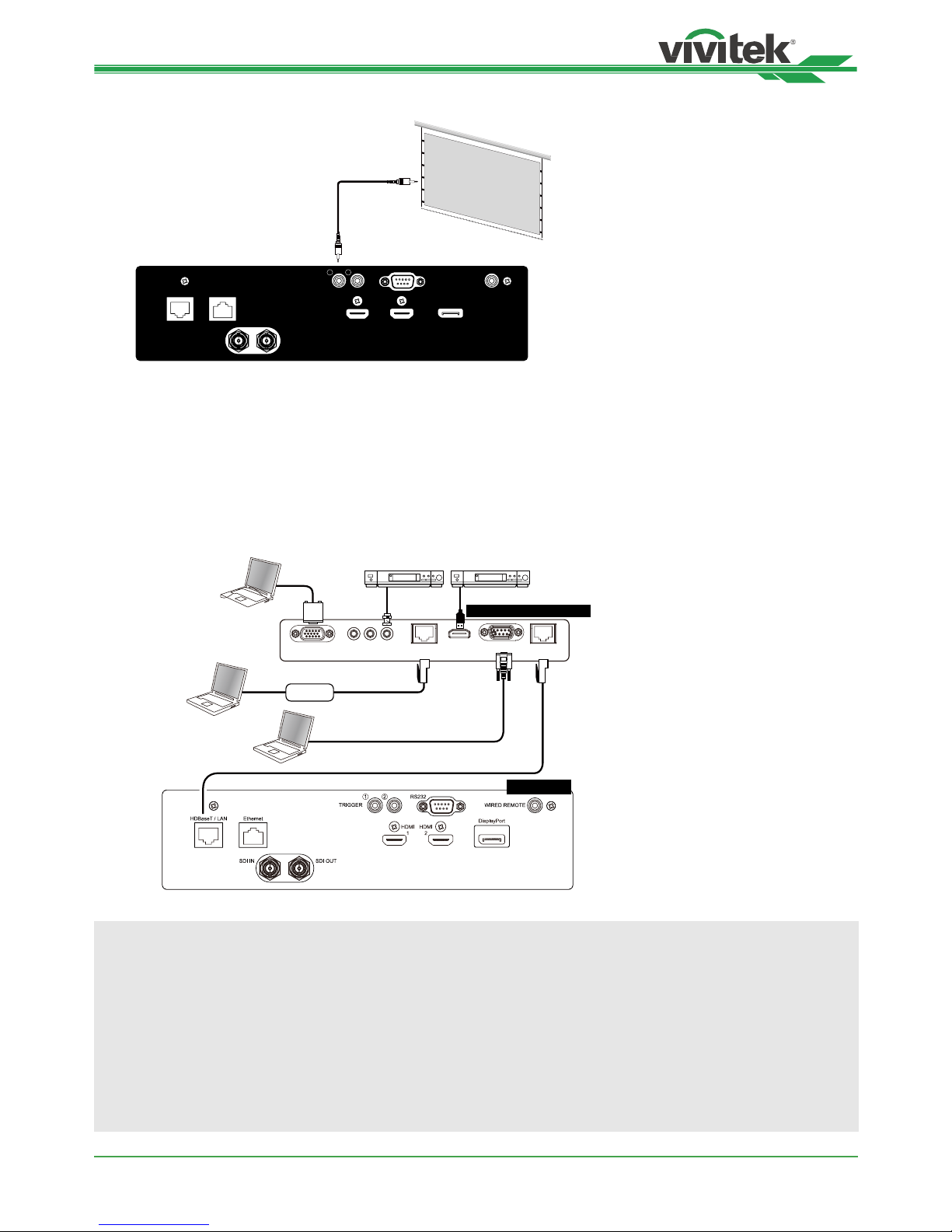
Connecting to the Screen Trigger
HDMI1HDMI
2
HDBaseT / LAN Ethernet
DisplayPort
RS232
WIRED REMOTE
SDI IN SDI OUT
TRIGGER
1 2
Screen
If your projection system includes the electric projection screen and other 12V trigger device, you can connect these
devices to the 12V trigger to output and congure the output 12V signal settings. The projector will output 12V signals
when it’s turned on. You can use the signal to control the screen or device.
Connecting to external HDBaseT Transmitter
The projector has a built-in HDBaseT receiver. With HDBaseT Transmitter (optional), the video, RS-232 and LAN
signals can be sent to the projector via a single RJ-45 cable. If the HDBaseT Transmitter you purchased supports the
input and output of the IR remote control, the control signals from the IR remote control can be sent to the DK8500Z
projector via the RJ-45 cable.
VGA IN RJ45
Lan
HDMI RS232 RJ45
HDBaseT
YPbPr
HDBaseT Transmitter
Projector
Control PC
Control PC
Hub
RS-232
DVD Player
VGA Cable
DVD Player
RJ-45 Cat5e or above
Note:
• The projector supports the video signal, R-232, IR remote control and the reception of the network control
signals but do not support Power over Ethernet (PoE).
• The baud rate will be switched to 9600 automatically. If RS232 command is sent via external HDBaseT
transmitter.
• If the command is sent via the HDBaseT transmitter, the longest transmission distance is 100 meters. The
projection may be interrupted or interfered, or the control signal cannot be sent if the transmission distance is
exceeded.
• Use the RJ-45 Cat5e or above cable and avoid entwining. Entwining may cause damage or interfering signal
transmission, reduce the transmission distance and degrade the image quality.
Page 29
DK8500Z-BK DLP Projector - User Manual
UM8500217EN00
29
Using the projector
Using On-Screen Display
Using the OSD Menu
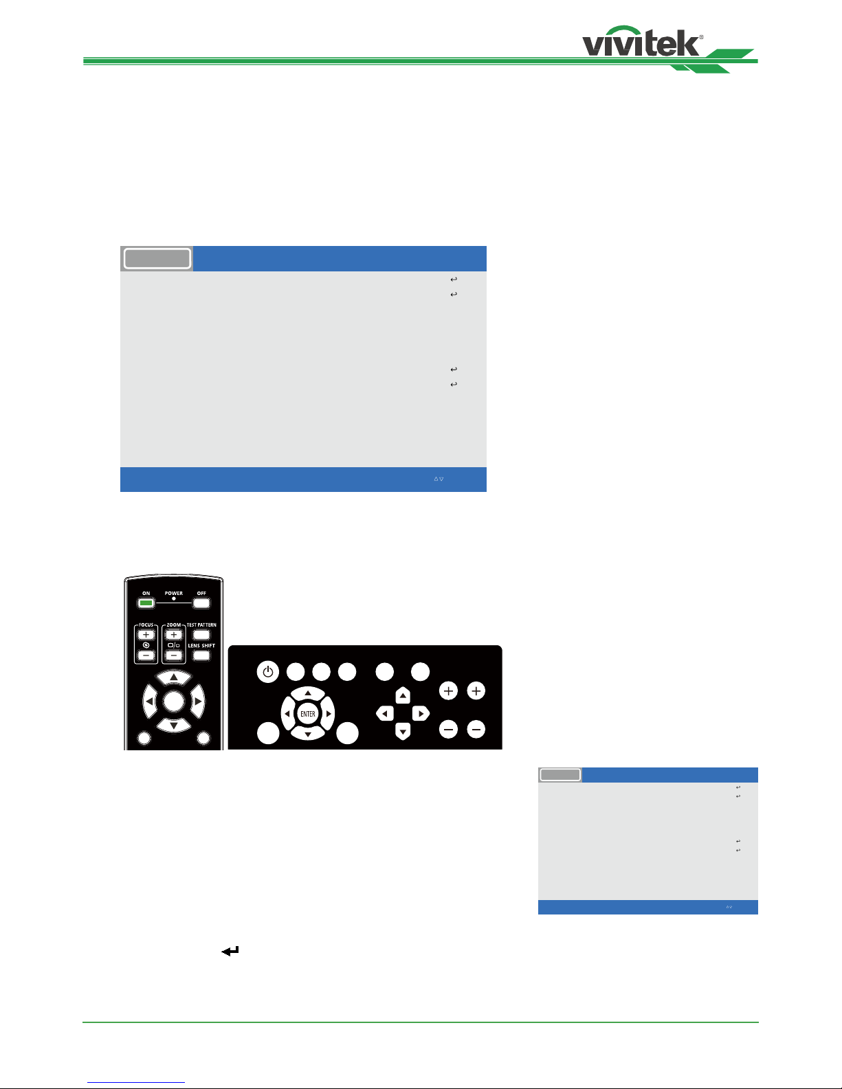
The projector has an On-Screen Display (OSD) that lets you make image adjustments, change various settings and
check current projector status.
Input Selection
PIP
Off
A
uto Source <Off >
Color Space <Auto>
A
spect Ratio <Source >
Overscan <Off >
Test Pattern
A
uto Sync
INPUTPICTURE ALIGNMENTCONTROL SERVICE
HDMI 1
3G-SDI
EXIT = Back Item Adjust ◄► Scroll Ⴃ
Ⴍ
炾►
炾►
炾►
炾►
Navigating the OSD
You can use the remote control or the control buttons on the projector to navigate and make changes to the OSD. The
following illustration shows the corresponding buttons on the remote control and on the projector
POWER
MENU EXIT
LENS
SHIFT
FOCUS ZOOM
INPUT
AUTO
SYNC
ASPECT CENTER LENS SHUTTER
MENU
EXIT
ENTER
1. To open the OSD, press the Menu button on the OSD control
panel or remote control. There are ve folders on the menu.
Press the cursor ◄ or ► buttons to move through secondary
menus.
Input Selection
PIP
Off
A
uto Source <Off >
Color Space <Auto>
A
spect Ratio <Source >
Overscan <Off >
Test Pattern
A
uto Sync
INPUTPICTURE ALIGNMENTCONTROL SERVICE
HDMI 1
3G-SDI
EXIT = Back Item Adjust ◄► Scroll Ⴃ
Ⴍ
炾►
炾►
炾►
炾►
2. Press ▲or▼ to select menu items and ◄or► to change values
for settings. Press to conrm the new setting.
3. Press RETURN to leave a submenu or MENU to close menu
Page 30

DK8500Z-BK DLP Projector - User Manual
UM8500217EN00
30
Menu Tree
Use the following table to quickly nd a setting or determine the range for a setting.
Main Menu Submenu
INPUT Input Selection Display Port
HDMI1
HDMI2
HDBaseT
3G-SDI
PIP PIP Option
PIP Input
Position
Auto Source Off
On
Color Space Auto
YPbPr
YCbCr
RGB-PC
RGB-Video
Aspect Ratio 5:4
4:3
16:10
16:9
1.88
2.35
Letterbox
Source
Native
Overscan Off
Crop
Zoom
Test Pattern White
Black
Red
Green
Blue
Cyan
Yellow
Magenta
Auto Sync Execute
PICTURE Picture Mode High Bright
Presentation
Video
Brightness
Contrast
Saturation
Hue
Sharpness
Color Temperature 5400K
6500K
7500K
9300K
Native
Gamma 1.0 / 1.8 / 2.0 / 2.2
/ 2.35 / 2.5 / S-Curve/ HDR / DICOM
Page 31

DK8500Z-BK DLP Projector - User Manual
UM8500217EN00
31
Main Menu Submenu
Input Balance Red Offset
Green Offset
Blue Offset
Red Gain
Green Gain
Blue Gain
HSG Red
Green
Blue
Cyan
Magenta
Yellow
White
Reset
Noise Reduction
Dynamic Black Off
On
ALIGNMENT Lens Lens Lock Off / On
Lens Control Zoom / Focus / Lens Shift
Lens Type NON-UST Lens / UST Lens
Lens Memory Load Memory/Save Memory/Clear
Memory
Center Lens
Digital Zoom Digital Zoom
Dgital Pan
Digital Scan
Blanking
Keystone
4 Corners
Rotation
Pinchshion / Barrel
Arc
Top
Bottom
Left
Right
Reset
Horizontal Keystone
Vertical Keystone
Rotation
Reset
Top Left Corner
Top Right Corner
Bottom Left Corner
Bottom Right Corner
Reset
Rotation / Reset
Horizontal
Vertical
Keystone
Reset
Top
Bottom
Left
Right
Reset
Edge Blend Edge Blend
Align Pattern
White Level
Black Level
Reset
Screen Format 16:10
16:9
4:3
CONTROL Language English/France/Spain/Germany
/ Portuguese/ Simple Chinese /
Chinese / Japanese / Korean
Page 32

DK8500Z-BK DLP Projector - User Manual
UM8500217EN00
32
Main Menu Submenu
Projection Mode Front Desktop / Front Ceiling / Rear
Desktop/ Rear Ceiling
High Altitude
Standby Mode
Off
Auto
Saving
ECO
Normal
Auto Power Off Off
On
Auto Power On Off
On
Network
Network
DHCP
IP Address
Subnet Mask
Gateway
DNS
Mac Address
Light Power Light Power
Custom Light Power
Constant Brightness
Background Black
Blue
Startup Logo Off
On
Infrared Remote Remote Sensor
ID Control Enable
Trigger Off
Screen
5:4
4:3
16:10
16:9
1.88
2.35
Letterbox
Source
Native
OSD Setting Menu Position
Menu Transparency
Time Out
Message Box
Control Panel Lock
Security Lock
SERVICE Model
Serial Number
Software Version 1
Software Version 2
Software Version 3
Control / Remote ID
Active Source
Signal Format
H/V Refresh Rate
Pixel Clock
Light Time
Thermal Status
Factory Reset
Page 33
DK8500Z-BK DLP Projector - User Manual
UM8500217EN00
33
Input Selection
PIP
Off
A
uto Source <Off >
Color Space <Auto>
A
spect Ratio <Source >
Overscan <Off >
Test Pattern
A
uto Sync
INPUTPICTURE ALIGNMENTCONTROL SERVICE
HDMI 1
3G-SDI
EXIT = Back Item Adjust ◄► Scroll Ⴃ
Ⴍ
炾►
炾►
炾►
炾►
OSD Menu – INPUT
Input Selection
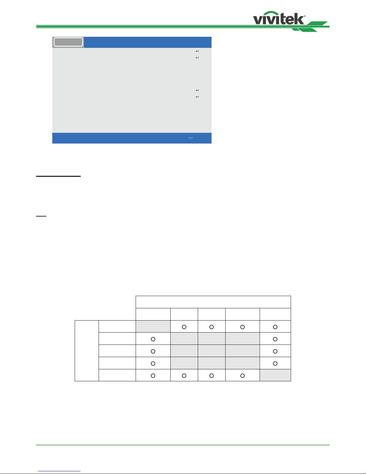
Use the shortcut key on the remote control or this function to select the input source; the Input options are as below.
The available input source of the product is DisplayPort, HDMI 1, HDMI 2, HDBaseT, and 3G-SDI.
PIP
This function allows you to split the screen for displaying the images from two input sources
PIP Option
Enable PIP by choosing “ON”, and two windows will be shown on the projected picture. The larger one is the
primary picture, the smaller one is the sub picture. By choosing “Off”, PIP function will be disabled, and only one
picture window projected.
PIP Input
Press ENTER to display available sources for the sub picture, and then select a source.
Note: The unavailable input sources of sub-menu will be gray out and cannot be selected. The available input
source of sub picture is as below combination list.
Main Picture
DisplayPort HDMI 1 HDMI 2 HDBaseT 3G-SDI
Sub Picture
DisplayPort
HDMI 1
HDMI 2
HDBaseT
3G-SDI
Page 34

DK8500Z-BK DLP Projector - User Manual
UM8500217EN00
34
Position
Find preferred location of PIP window.
Top Left: Display sub picture at top left of the screen.
Bottom Left: Display sub picture at bottom left of the screen.
Top Right: Display sub picture at top right of the screen.
Bottom Right: Display sub picture at bottom right of the screen.
PBP: Display sub picture next to main picture, the main screen is shrined to the same size as sub picture.
2
1
2
1
2
1
2
1
21
Bottom Left
Top Left
Bottom Right
Top Right
PBP
Auto Source
The Auto Source functions “ON” lets projector automatically search for the input signal.
Color Space
This function allows you to change the corresponding color space for the input signal in most cases, the default is
Auto.
Auto: The projector detects the input signal and switches to the corresponding color space automatically.
YPbPr: Set the color space to ITU-R BT 601.
YCbCr: Set the color space to ITU-R BT 709.
RGB-PC: Use the RGB color space and set the black to 0, 0, 0 RGB, while set the white to 255, 255, 255 RGB (if
an 8-bit image is used).
RGB-Video: Use the RGB color space and set the black to 16, 16, 16 RGB while set the white to 235, 235, 235 (if
an 8-bit image is used) to correspond to the luminance value dened in the digital component standard.
Aspect Ratio
This function allows the user to adjust the aspect ratio of the projection image by ◄ ► keys.
Overscan
Noise may appear on the edge of the projected image or image may be small than projected image, select below
option to hide the noise or extend the image.
Off: Display the original image.
Crop: Hide the edge of the image
Zoom: Extend the image to t the projected area as possible.
Test Pattern
The built-in images are provided for installation and adjustment. You can select Test Pattern on OSD or the TEST
PATTERN button on the remote control to show the test pattern. Press the ◄ or ► to select pattern or press EXIT key
again to exit the test pattern. The available test pattern options are Off / White / Black / Red / Green / Blue / Cyan /
Yellow / MagentaWhite, Green, Crosshatch, Color Bar, Black, Blue, H-Burst, Red, Chess Board and V Burst.
Auto Sync
You can use this function to execute signal source auto synchronization.
Page 35

DK8500Z-BK DLP Projector - User Manual
UM8500217EN00
35
Picture Mode
Color Temperature
Gamma
Input Balance
HSG
ˑ
炾►
炾►
Scroll Ⴃ
ႭItem Adjust ◄►EXIT = Back
Hue
0 ssenprahS
001 ssenthgirB
001 tsartnoC
001 noitarutaS
INPUTPICTURE ALIGNMENTCONTROL SERVICE
High Brigh
t
炾►
Native
炾►
2.2
炾►
100
OSD Menu – PICTURE
Picture Mode
Use ◄or► to select desired picture mode
High Bright: The highest brightness output mode is suitable for the application where the highest brightness
output is needed.
Presentation: The best projection effect is suitable for the presentation or picture.
Video: The mode is suitable for playing video content.
Brightness
Press ENTER, and use ◄ or ► to increase or decrease the level of brightness.
Contrast
Press ENTER, and use ◄ or ► to adjust the contrast of the projected image.
Saturation
Press ENTER, and use ◄ or ► to adjust the level of saturation.
Hue
Press ENTER, and use ◄ or ► to adjust the level of hue.
Sharpness
Press ENTER, and use ◄ or ► to adjust the sharpness, which changes the high-frequency details.
Color Temperature
The default of color temperature is Native, and it is suitable for most situations. As color temperature rises, the picture
will appear bluer, while as the color temperature decreases, the picture will appear redder. The available options are
Native, 5400K, 6500K, 7500K and 9300K
Gamma
When the ambient light is so bright that may affect the projection of the details in the dim area of the image, you can
change the gamma to adjust the chrominance. The available options are 1.0, 1.8, 2.0, 2.2, 2.35, 2.5 and S-Curve.
Input Balance
When ambient light is too bright or changes, the projected image details may be affected, you can adjust the option
to make the projected colors of image closer to desired colors. There are two options for ne tuning Red, Green and
Blue
Page 36

DK8500Z-BK DLP Projector - User Manual
UM8500217EN00
36
Offset: These three options will shift the color spectrum for the whole image and change its brightness, if minimal
amount of red, green or blue appears in the gray areas, you can adjust the offset of the corresponding color
accordingly. By increasing the offset, the image brightness will become lower.
Gain: These three options are used to increase or decrease the range of color input for the entire image. If
minimal amount of red, green or blue appears in the gray areas, lower the gain of the corresponding color
accordingly. As gain increases, the contrast of the image will become lower.
HSG
HSG is a function to adjust Hue, Saturation and Gain independently, it allows for specied color adjustments that
are more intuitive. You can adjust Hue, Saturation and Gain for Red, Green, Blue, Cyan, Magenta, Yellow and white
independently.
Noise Reduction
Use ◄► to adjust the noise of the projected image. This function is used to remove the noise of the image with
interlaced scanning input. Generally, noise reduction can lower the high-frequency details and make the image softer.
Dynamic Black
This is function can be used to enhance the black level of the projected image.
Smooth Picture
This function should always be “On” to display the 4K signal image quality per specication.
Lens
炾►
Digital Zoom
炾►
˕ Arc
炾►
Edge Blend
炾►
Screen Format
炾►
INPUTPICTURE ALIGNMENTCONTROL SERVICE
Blanking
Scroll ႣႭItem Adjust ◄►EXIT = Back
16:9
炾►
炾►
˕ Rotation
˕ Pincushion / Barrel
˗ Keystone
˕ 4 Corner
s
炾►
炾►
OSG Menu – ALIGNMENT
Lens Lock
This function can be used to disable lens control for preventing unauthorized operation or disoperation in lens control
related functions including Lens Shift, Zoom/Focus adjustment and Center Lens. Recommend to turn on Lens Lock
function to disable the Lens control after lens adjustment is done.
Note:
• Turning on Lens Lock will disable lens control function including Lens Shift, Center Lens and Zoom/Focus
adjustment, please make sure Lens Lock is disable before you perform the lens control function.
Page 37

DK8500Z-BK DLP Projector - User Manual
UM8500217EN00
37
Lens Control
Select this function to open Lens Control menu for adjustment of Zoom, Focus, or Shift. You can use the ENTER
button to switch the Zoom / Focus or Shift menu. Use ▲or▼ to adjust zoom and vertical shift of the lens, or use ◄ ►
to adjust focus and horizontal shift of the lens.
Lens Type
There are eight projections lens can be used in DK8500Z; the initial projection position of Ultra Short Throw (UST)
Lens is different to other seven projection lenses. The projector preset two initial projection positions for these two
types accordingly, Center Lens function can moves the lens to the initial position (center) automatically per the setting.
Please set this option to UST Lens if Ultra Short Throw Lens is installed in the projector, otherwise please set it to
Note:
• There are two default positions, one is for regular zoom or xed focus lens (Non-UST), the reference position
is 0% of image width in horizontal shift and 0% of the image height in vertical shift; anther one is for Ultra Short
Throw Lens (UST), the default position is around 0% of image width in horizontal shift and 56% of image height
in vertical shift. When performing Center Lens functions, projector will move the lens to the default position
according to Lens type setting.
• If Ultra Short Throw Lens is installed and UST Lens is selected, you can perform Center Lens to move Lens to
initial projection position automatically.
• If using Ultra Short Throw Lens and setting to Non-UST Lens, the lens will be moved to the position which is
lower than the default position of Ultra Short Throw Lens after performing Center Lens function, it causes the
projected image is blocked by the top cover of the projector. In this case, please perform the Lens shift function
to move up the Lens till the image can be projected normally.
• please make sure Lens Type setting is set to Non-UST Lens then perform Center Lens function if other zoom
lens or xed focus lens is used, or lens shift range is limited, center position of the lens is not correct.
Lens Memory
This projector supports Lens Memory function, Lens shift, Zoom and Focus memory can be stored in the projector up
to 10 sets. You can load the stored memory setting to set up the lens automatically.
Load Memory: Use ▲▼ to select the desired memory setting then press ENTER button to execute the lens
setting, the projector will adjust the Lens position, Zoom and Focus automatically.
Save Memory: Use ▲▼ to select the memory set for storing the setting then press ENTER button to conrm.
Clear Memory: Select the memory set to be cleared then press ENTER button to conrm clearing memory set.
Center Lens
This is the lens calibration function, the projector calibrates the lens shift, focus and zoom parameters for the precise
lens memory function. After performing this function, the lens will be moved to the center position as factory default
setting.
Note:
• There are two default center positions for UST (Ultra Short Throw) Lens and non-UST Lens, make sure Lens
Type setting is correct before performing this function.
• If Ultra Short Throw Lens is installed, make sure the support kit is detached before performing Center Lens.
Digital Zoom
Press ENTER button to select the options to enlarge the image or shift the image.
Digital Zoom: Use ◄► to enlarge the projected image.
Digital Pan: Use ◄► to move the projected image horizontally. This function is only available when projected
image is enlarged.
Digital Scan: Use ◄► to move the projected image vertically. This function is only available when projected
image is enlarged.
Reset: The setting will be reset to default value.
Page 38

DK8500Z-BK DLP Projector - User Manual
UM8500217EN00
38
Blanking: This function can adjust the edges of the image and hide surplus sections of the projection.
Top: Press▲▼ to adjust the top blanking area on the projected picture.
Bottom: Press▲▼ to adjust the bottom blanking area on the projected picture.
Left: Press ◄► to adjust the left blanking area on the projected picture.
Right: Press ◄► to adjust the right blanking area on the projected picture.
Top
Bottom
Left
Right
Blanking area
Top
Bottom
RightLeft
Blanking area
Reset: All the settings toward blanking will set to default.
Keystone: Press ◄► to correct horizontal distortion or ▲▼ to correct vertical distortion.
4 Corners
Top Left Corner: Press ◄► to correct the distortion at top-left of the picture.
Top Right Corner: Press ◄► to correct the distortion at top-right of the picture.
Bottom Left Corner: Press ◄► to correct the distortion at bottom-left of the picture.
Bottom Right Corner: Press ◄► to correct the distortion at bottom-right of the picture.
Reset: The setting will be reset to default value.
Rotation: Press ◄► to correct incorrect angle of image.
Pincushion / Barrel: Press ◄► to correct pincushion/barrel distortion.
Arc: Press ◄► to correct distorition of indivisual side including top, bottom, left or side.
Edge Blend
Edge Blend function requires multiple projectors to simultaneously project on the same screen. Use this function to
adjust the uniformity of image. To use this function, Edge Blending must be enabled on both projectors. The functions
as follows can be only adjusted when Edge Blend is turned on.
Edge Blend: If the user would like to function Edge Blend, turn this function to On.
Align Pattern: If user turns this function to On, the projector will show pattern for user to adjust the overlapping
part of projection
White Level: White Level is used to set the overlapped area for blending in multi-projection application, the
overlapping When projecting White, the area where the two images overlap is projected twice the projectors’ white
output levels. The solution is to adjust the White Level. First make sure that the units connected to the projectors
are outputting black. Then increase the White Level (Top, Bottom, Left, and Right) until the non-overlap area’s
brightness matches the overlap area.
Black Level: The purpose of Black Level is to increase the black level of non-overlapping area. When projecting
black, the area where the two images overlap projects twice the projectors’ black output levels. The solution is
to adjust the Black Level. First make sure that the units connected to the projectors are outputting black. Then
increase the Black Level (Top, Bottom, Left, and Right) until the non-overlap area’s brightness matches the overlap
area.
Reset: All the settings toward edge blend will set to default.
Screen Format: Sleet the screen format to 16:10, 16:9 and 4:3.
Page 39
DK8500Z-BK DLP Projector - User Manual
UM8500217EN00
39
Language
Projection Mode
High Altitude Auto
Standby Mode Saving
Auto Power Off <Off >
Auto Power On <Off >
Network
Light Power
Backgroun
dB
lack
Startup Logo <On>
ˑ
INPUTPICTURE ALIGNMENT CONTROL SERVICE
EXIT = Back Item Adjust ◄► Scroll Ⴃ
Ⴍ
炾►
炾►
炾►
炾►
炾►
炾►
Front Desktop
炾►
OSD Menu – CONTROL
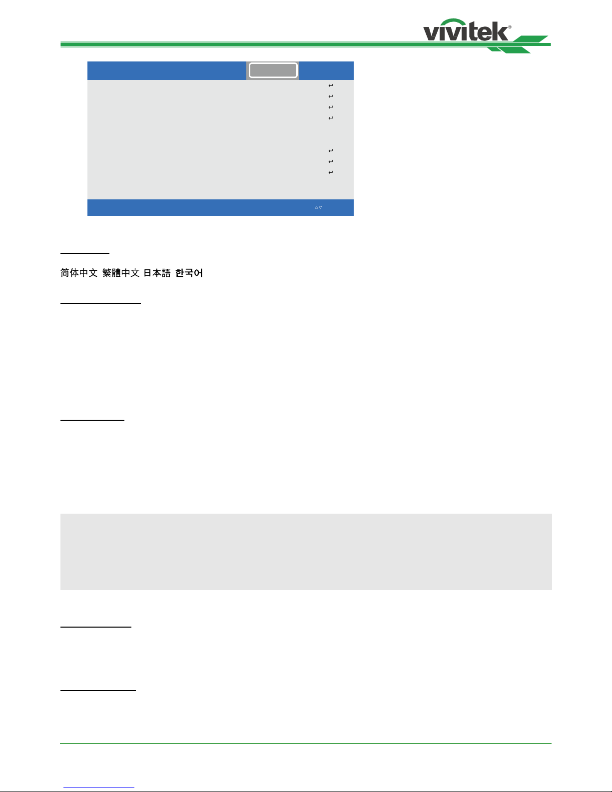
Language
Select desisted OSD language, the available languages options are English, Francis, Española, Deutsch, Portuguese,
, , , .
Projection Mode
The projection mode option can be used to change the orientation of the projected image or ip the projected image.
Front Desktop: Install the projector on the table and project the image on the screen forward.
Front Ceiling: Mount the projector on the ceiling and project the image on the screen forward, the image is
overturned.
Rear Desktop: Install the projector on the table and project the image from the rear of the screen.
Rear Ceiling: Mount the projector on the ceiling and project the image from the rear of the screen, the image is
overturned.
High Altitude
Use this function to adjust the cooling fan of the projector to get well cooling if the projector is installed in an area
over 5000 feet. The projector is equipped with altitude sensor which is capable of detecting atmosphere pressure for
estimating altitude; it can adjust automatically to corresponding setting based on estimated altitude if this option is set
to Auto. If you prefer to set it by manual, you can select On or Off.
Off: Turn off High Altitude mode if the projector is installed in an area under 5000 feet.
On: Turn on High Altitude mode if the projector is installed in an area over 5000 feet.
Auto: Set up this mode automatically by estimated altitude.
Note:
• Estimate Altitude is calculated by atmosphere pressure, it may have the tolerance comparing to actual altitude.
• If any over temperature or system protection message, please adjust High Altitude by Manual.
• In some application, regular cooling fan setting may not supply enough cold air for system cooling even the
projector is installed in an area under 5000 feet. In this case, please set High Altitude to On.
Standby Mode
Saving: standby power consumption less than 0.5W, Ethernet control function is not workable.
ECO: standby power consumption less than 3.0W, Ethernet control function is workable; HDBaseT is workable.
Normal: standby power condusmption less than 6.0W; HDBaseT only can work at this condition.
Auto Power Off
This function is set to OFF by default. When it is set to ON and no input signal is received within 20 minutes, the
projector will turn off automatically.
Page 40

DK8500Z-BK DLP Projector - User Manual
UM8500217EN00
40
Auto Power On
This function is set to OFF by default. When it is set to ON, the projector will turn on automatically when y AC power
is turned on next time. You can use this function and the power switch (instead of the remote control) to turn on the
projector. Set this function to OFF if it’s unnecessary.
Network
Use this function to congurator the network settings so that you can control the projector via the network.
Press ▲▼ and Enter button to select Network and network settings. Please refer to Remote Communication Manual
for further information.
DHCP: Set DHCP to ON/OFF. When DHCP is set to ON, the DHCP server of the domain will assign an IP address
to the projector. The IP address will appear on the IP address window without need to make any input. If the
domain cannot assign any IP address, 0.0.0.0 will be shown on the IP address window.
IP: To specify an IP address, press the Enter button to show the IP address input window. Use the ◄► button
to select the number in the address to change. Use the ▲▼ button to increase or decrease the number in the IP
address. Network IP Address 172. xxx. xxx. xxx.
Subnet Mask: Set the subnet mask. The input method is the same as the setting for IP address.
Gateway: Set the gateway. The input method is the same as the setting for IP address.
DNS: Set the DNS. The input method is the same as the setting for IP address.
MAC Address: Show projector’s MAC Address.
Light Power
Use the ◄► function to select the Eco, Normal or Custom Power Level mode.
Eco: Projection operates in the energy-saving mode, which is equivalent to 80 % power of light source.
Normal: Projection operating with normal light power can obtain the brightest projection display.
Custom Power Level: User can decide the power level depending on his or her preference.
Custom Power Level
Use the ◄► function to select the Custom Power Level. This function is available only when the Light Power is set to
Custom Power Level, which range is allowed to adjust from 20% to 100% of normal mode, and it cannot be selected
under the Normal or Eco mode.
Constant Brightness
Use the ► to select Constant Brightness ON or OFF. Constant Brightness ON is to always keep the required
brightness by monitoring drive laser power and automatically adjust the laser power to meet the reqired level.
Background
User can use this function to specify the image displayed on the blank screen when there is no input signal. The
selectable items are Black and Blue, the default setting is Black.
Startup Logo
Press ENTER button, and use the ◄► function to turn on / off the Startup Logo.
Infrared Remote
Remote Sensor: The default is On. However, there are three conditions that will be suggested to turn off “Remote
Sensor”; the possible condition is that if the user uses wired control, he can set this function to Off, or that if the
projector IR location is exposed to the bright sunlight or uorescence, or that projector control is not controlled by
remote. If the user would like to reset to On, user can only set by OSD panel or RS-232.
ID Control Enable: This option allows you to enable the projector ID control function. You can turn on this function
and give an ID number for the projector, then set the same ID number for the remote control to match the projector
ID. After ID code is set, you can control the specied projector by the remote control.
Control ID Number: Select the option then press ◄ or ► to set the ID number of the projector, this option is
selectable when Projector ID Control is enabled.
Page 41

DK8500Z-BK DLP Projector - User Manual
UM8500217EN00
41
Trigger
The projector is provided with a set of trigger output. User can connect the trigger to the screen with projector by the
cable. If user does so, once the projector is powered, the screen would be automatically turned on as well. There is a
2-3 second delay to activate this function. The selectable aspect ratios are as follows:
Off: Turn off screen trigger
Screen: Outputs 12V of power on Trigger for whichever aspect ratio
5:4: Outputs 12V of power on Trigger when Aspect Ratio is set to 5:4.
4:3: Outputs 12V of power on Trigger when Aspect Ratio is set to 4:3.
16:10: Outputs 12V of power on Trigger when Aspect Ratio is set to 16:10.
16:9: Outputs 12V of power on Trigger when Aspect Ratio is set to 16:9.
1.88: Outputs 12V of power on Trigger when Aspect Ratio is set to 1.88.
2.35: Outputs 12V of power on Trigger when Aspect Ratio is set to 2.35.
Letterbox: Outputs 12V of power on Trigger when Aspect Ratio is set to Letterbox.
Source: Outputs 12V of power on Trigger when Aspect Ratio is set to Source
Native: Outputs 12V of power on Trigger when Aspect Ratio is set to Native.
OSD Settings
Menu Position: Adjust menu position through this function, the available position options are at Top-Left, Top-
Right, Bottom-Left, Bottom-Right and center of the screen.
Menu Transparency: Change the transparency of OSD Menu, the background color of the OSD can be adjusted
from darker to lighter if you want to display complete projected image.
Time Out: Set up the timer to exit OSD menu, the available options are Always On, 10 Seconds, 30 Seconds and
60 Seconds.
Message Box
This function allows you to disable the pop-up message at bottom-right of the screen.
Page 42

DK8500Z-BK DLP Projector - User Manual
UM8500217EN00
42
Model
Serial Number
Software Version 1
Software Version 2
Software Version 3
X / XDI etomeR / lortnoC
Active Source
Signal Format
H/V Refresh Rate
Pixel Clock
ˑ
INPUTPICTURE ALIGNMENTCONTROL SERVICE
EXIT = Back Item Adjust ◄► Scroll Ⴃ
Ⴍ
DK8500Z
WDU80905410010
MD11-VD11-FD09-0.0.3
5
STEP_D08-24-17-3120
HDMI 1
593.60MHz
134.8KHz / 59.9Hz
2.0.8.0-P503
OSD Menu – SERVICE
Model
Display the project model name.
Serial Number
Display the serial number of the projector.
Software Version 1 / Software Version 2 / Software 3
Display the software version in the projector.
Control/Remote ID
Display current projector ID and remote control ID number.
Active Source
Display the current input source information.
Signal Format
Display current input source format
H/V Refresh Rate
Display horizontal and vertical refresh rate of the current picture.
Pixel Clock
Display pixel clock of the current input signal.
Light Time
Display accumulated usage of projection light source
Thermal Status
Display current of the thermal management components.
Factory Reset
The user can use this function to reset all the settings to factory default; light time.
Page 43
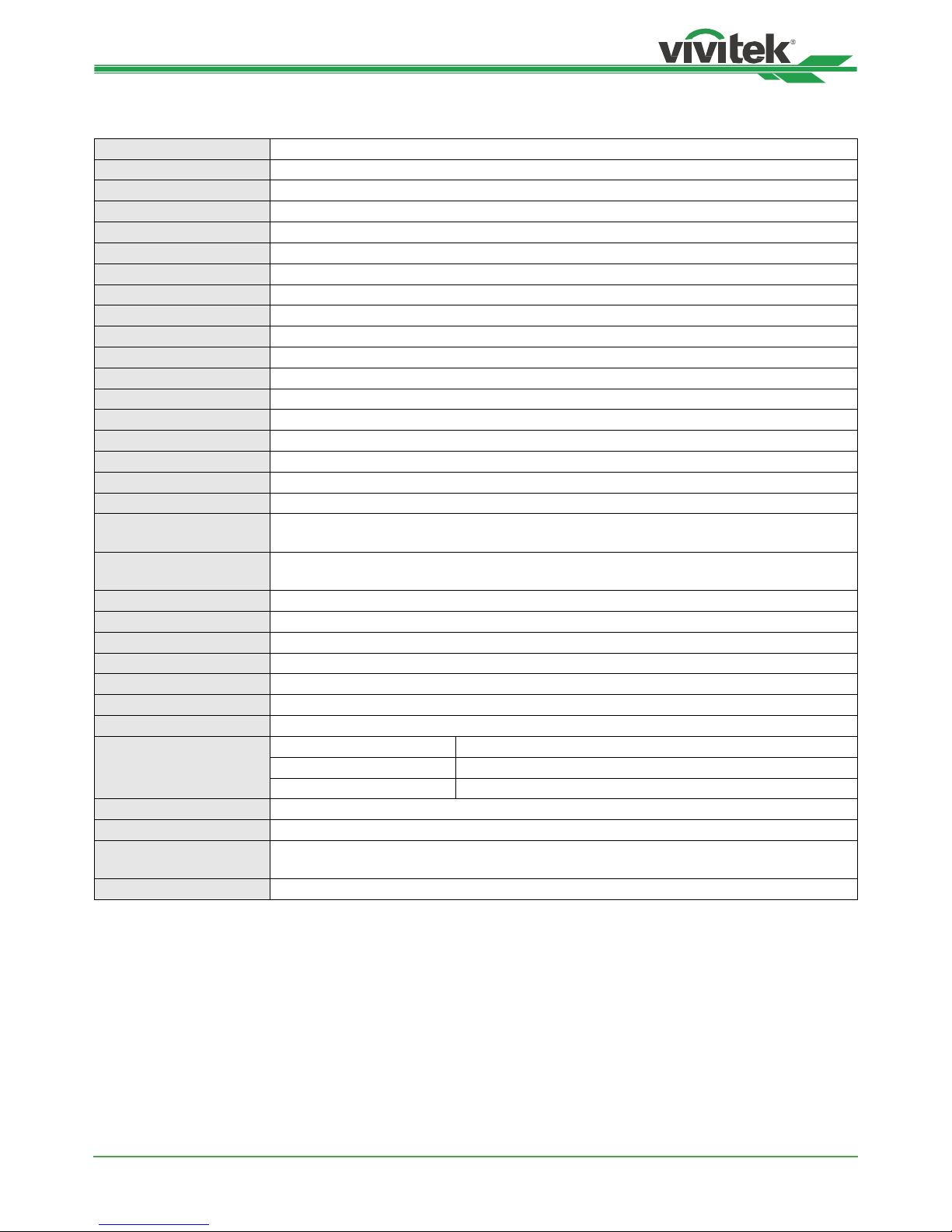
DK8500Z-BK DLP Projector - User Manual
UM8500217EN00
43
Product Specication
Display Type Single Chip 0.67" DLP Technology
Brightness 7,500 ANSI Lumens
Native Resolution 4K-UHD(3840 x 2160) with SP On
Maximum Resolution 4K-UHD (3840 x 2160)@60Hz
Contrast Ratio 100,000:1 (Full On/ Full Off) 8000 : 1
Illumination Type Laser Phosphor
Throw Ratio* 1.73 - 2.27:1 (Option)
Image Size (Diagonal)* 40" - 500"
Projection Distance* 1.45 - 24.85m (4.77ft to 81.52ft)
Projection Lens* F = 1.7 - 1.9, f = 26 - 34mm
Zoom Ratio* 1.3x
Aspect Ratio 16:10
Offset Motorized Lens Shift
Keystone Correction Horizontal ±60°, Vertical ±40° (adjustable range of single direction)
Horizontal Frequency 15, 30 – 90Hz
Vertical Scan Rate 50 - 85Hz
Edge Blending Yes (Built-In)
Warping Yes (Built-In)
Adjustable
Lens Shift Range
Vertical: -33% to +64%, Horizontal: -14% to 24%
I/O Connection Ports
DisplayPort x1, HDMI v2.0 (x2), 3G-SDI-In/Out, RS-232, 12V Trigger, Wired Remote,
HDBaseT™, RJ45.
Projection Method Table Top, Ceiling Mount (Front or Rear), Free-tilt , Portrait
Security Solutions Kensington® Security Slot, Security Bar, Anti-Theft Lens Screw
Dimensions
(WxDxH) 500 x 580 x 205mm (19.7” x 22.8" x 8.1")
Weight 29kg (63.9lbs)
Available Colours Black
Noise Level 40dB (Normal Mode)
Power Supply AC 100-240V, 50/60Hz
Power Consumption
Normal Mode 890W@100Vac, 845W@240Vac
Saving Power On Less than 0.5W
Standby Power Off (Eco) Less than 3W
Operation Condition At temperature 0 to 40°C, relative humidity 10% to 85%, non-condensation
Storage Condition At temperature -10 to 60°C,relative humidity 5% to 95%, non-condensation
Standard Accessories
AC Power Cord, HDMI Cable, Remote Control w/Batteries and Cable, Lens Cap, Anti-
Theft Lens Screw, Documentation Kit
Optional Accessories Interchangeable Lens Options
*Note: Standard Lens
**Note: Lens shift compatibility with all lenses except D88-WF18501 Wide Fixed Lens and D88-UST01B Ultra-Short
Throw Lens
Page 44
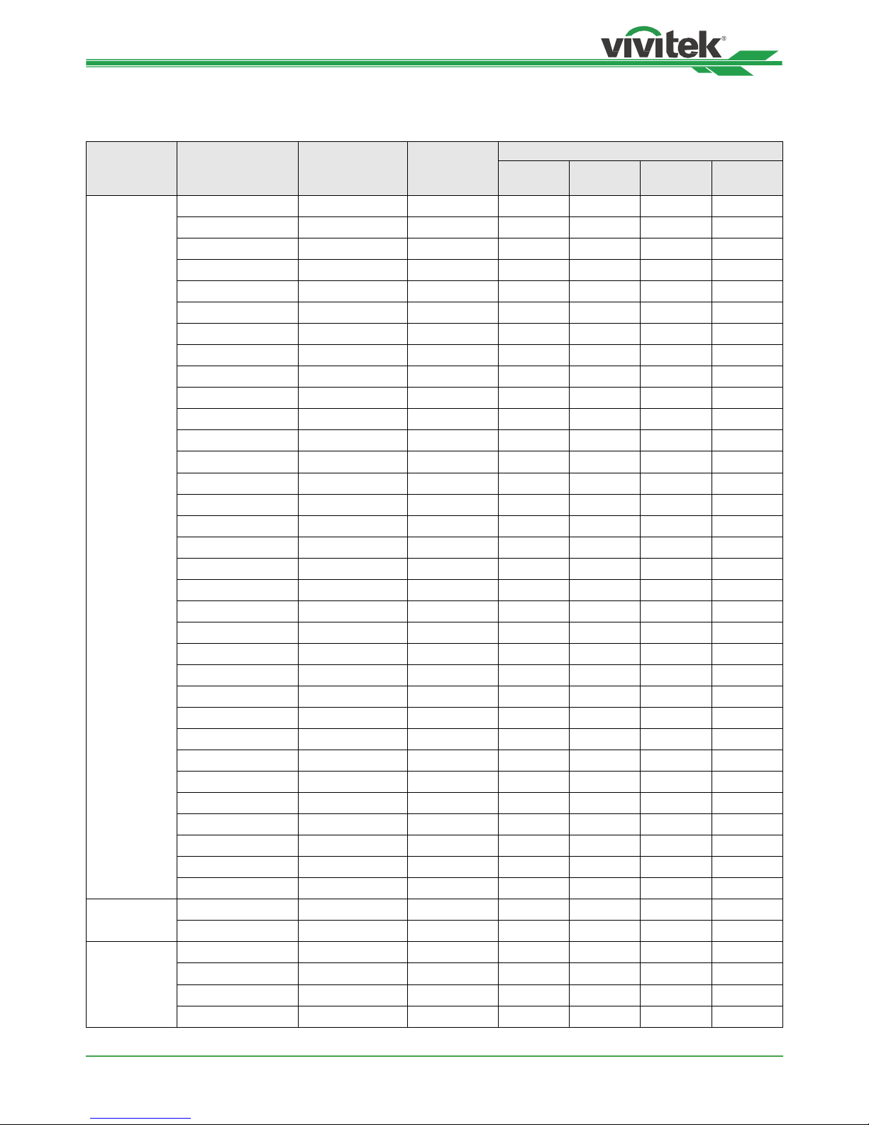
DK8500Z-BK DLP Projector - User Manual
UM8500217EN00
44
Supported Signal Input Timing
2D formats
Signal
Format
Resolution
Frame Rate
(Hz)
Display Port
HDMI / HD-BaseT
RGB
YUV
(8-bit)
YUV
(10-bit)
YUV
(12-bit)
PC
640x480 59.94 X X
640x480 74.99 X X
640x480 85 X X
800x600 60.32 X X
800x600 75 X X
800x600 85.06 X X
848x480 47.95 X X
848x480 59.94 X X
1024*768 60 X X
1024*768 75 X X
1024*768 85 X X
1280x720 47.95 X X
1280x1024 60.02 X X
1280x1024 75.02 X X
1280x1024 85.02 X X
1600x1200 60 X X
1600x1200 120 X X
1920x1080 47.95 X X
1680x1050 59.94 X X
1920x1200 RB 50 X X
1920x1200 RB 60 X X
1920x1200 RB 100 X X
1920x1200 RB 120 X X
1400X1050 60 X X
1366 x 768 60 X X
1440 x 900 60 X X
1280 x 768 60 X X
1280 x 800 60 X X
1280 x 960 60 X X
2712x1528 50 X X
2712x1528 60 X X
2712x1528 100 X X
2712x1528 120 X X
Apple Mac
640x480 66.59 X X
832x624 74.54 X X
SDTV
480i 59.94
1440x480i 60 X X X X
1440x576i 50 X X X X
576i 50
Page 45
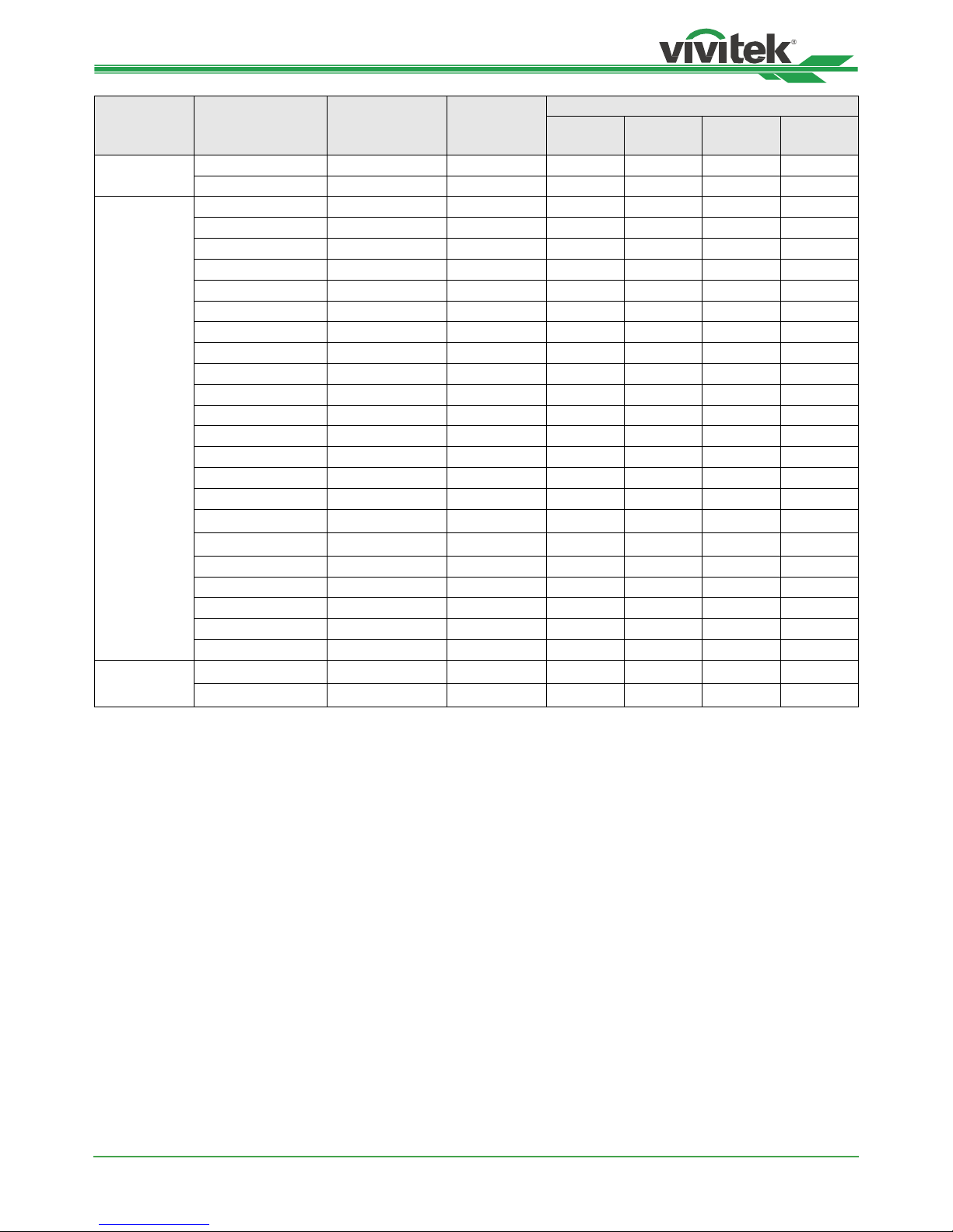
DK8500Z-BK DLP Projector - User Manual
UM8500217EN00
45
Signal
Format
Resolution
Frame Rate
(Hz)
Display Port
HDMI / HD-BaseT
RGB
YUV
(8-bit)
YUV
(10-bit)
YUV
(12-bit)
EDTV
480p 59.94 X X X X X
576p 50 X X X X X
HDTV
1035i 60 X X X X X
1080i 50 X X X X X
1080i 59.94 X X X X X
1080i 60 X X X X X
720p 50 X X X X X
720p 59.94 X X X X X
720p 60 X X X X X
1080p 23.98 X X X X X
1080p 24 X X X X X
1080p 25 X X X X X
1080p 29.97 X X X X X
1080p 30 X X X X X
1080p 50 X X X X X
1080p 59.94 X X X X X
1080p 60 X X X X X
1080p 100 X X
1080p 120 X X
2K 24/25/30/50/60 X X X X X
4K 24/25/30 X X X X X
4K 50/60 X X(8 Bits) X X(4:2:2) X(4:2:2)
1080p 100/120 X X X X X
2560x1600 100/120 X X X X X
PsF formats
1080sf 30
1080sf 25
* HDBaseT support 4K 30Hz @4:2:2
Page 46
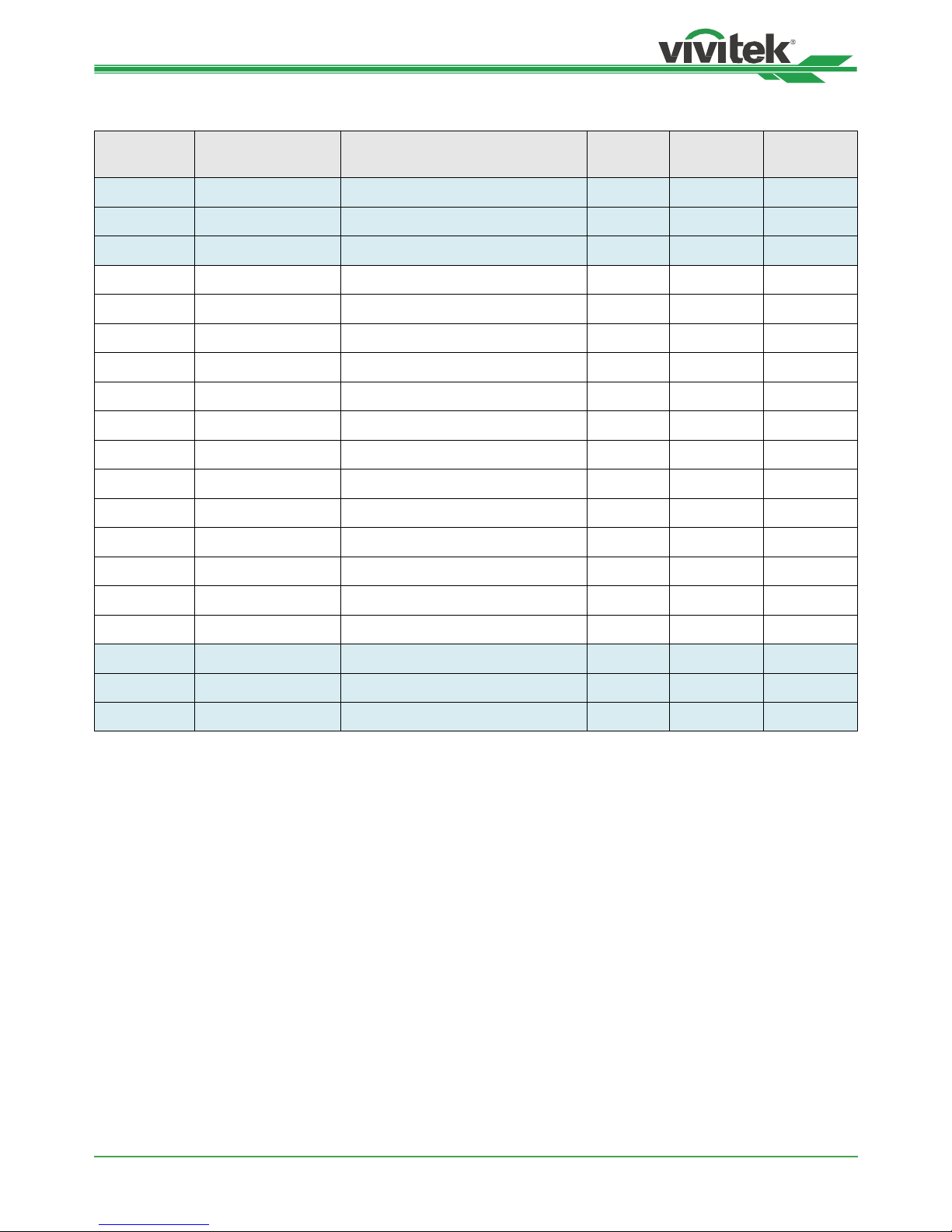
DK8500Z-BK DLP Projector - User Manual
UM8500217EN00
46
3G-SDI Format
Timing SDI Link mode Signal Standards
Color
Encode
Sampling
Structure
Bit Depth
NTSC SD SMPTE 259M-C 270Mbps SD YCbCr 4:2:2 10
PAL SD SMPTE 259M-C 270Mbps SD YCbCr 4:2:2 10
1035i60 HD SMPTE 292M 1.5Gbps HD YCbCr 4:2:2 10
1080i59 HD SMPTE 292M 1.5Gbps HD YCbCr 4:2:2 10
1080i60 HD SMPTE 292M 1.5Gbps HD YCbCr 4:2:2 10
1080P30 HD SMPTE 292M 1.5Gbps HD YCbCr 4:2:2 10
1080P25 HD SMPTE 292M 1.5Gbps HD YCbCr 4:2:2 10
1080i50 HD SMPTE 292M 1.5Gbps HD YCbCr 4:2:2 10
1080P24 HD SMPTE 292M 1.5Gbps HD YCbCr 4:2:2 10
720P60 HD SMPTE 292M 1.5Gbps HD YCbCr 4:2:2 10
720P50 HD SMPTE 292M 1.5Gbps HD YCbCr 4:2:2 10
1080Sf25 HD SMPTE 292M 1.5Gbps HD YCbCr 4:2:2 10
1080Sf30 HD SMPTE 292M 1.5Gbps HD YCbCr 4:2:2 10
1080P50 3G Level A SMPTE 424M 3Gbps YCbCr 4:2:2 10
1080P59 3G Level A SMPTE 424M 3Gbps YCbCr 4:2:2 10
1080P60 3G Level A SMPTE 424M 3Gbps YCbCr 4:2:2 10
1080P50 3G Level B SMPTE 424M 3Gbps YCbCr 4:2:2 10
1080P59 3G Level B SMPTE 424M 3Gbps YCbCr 4:2:2 10
1080P60 3G Level B SMPTE 424M 3Gbps YCbCr 4:2:2 10
Page 47
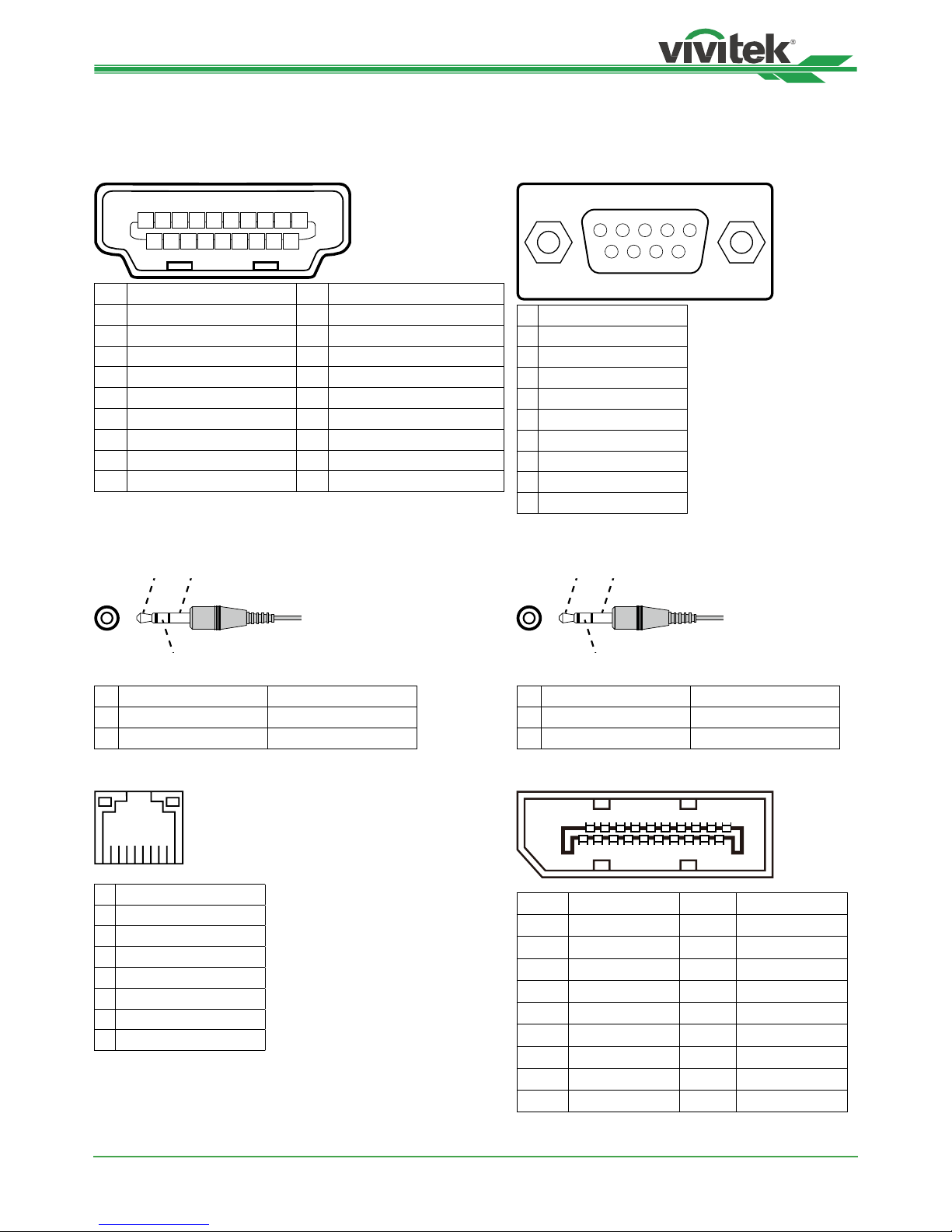
DK8500Z-BK DLP Projector - User Manual
UM8500217EN00
47
Congurations of Terminals
HDMI(19 pin Type A) Serial Control Termina
(RS-232, D-sub 9 pin)
1 3 5 7 9 11 13 15 17 19
2
4 6 8 10 12 14 16 18
1 T.M.D.S. Data 2+ Input 11 Ground
2 Ground 12 T.M.D.S. Clock C- Input
3 T.M.D.S. Data 2- Input 13 CEC
4 T.M.D.S. Data 1+ Input 14 N.C
5 Ground 15 SCL
6 T.M.D.S. Data 1- Input 16 SDA
7 T.M.D.S. Data 0+ Input 17 Ground
8 Ground 18 P5V
9 T.M.D.S. Data 0- Input 19 HPD
10 T.M.D.S. Clock C+ Input
9876
54321
Serial
1 N.C
2 RXD
3 TXD
4 N.C
5 Ground
6 N.C
7 Short with pin8
8 Short with pin7
9 N.C
Screen Trigger Wired Remote
Tip Sleeve
Ring
Tip Sleeve
Ring
Tip Sleeve
Ring
Tip Sleeve
Ring
1 Tip VCC(12V)
2 Sleeve- Ground
3 Ring Signal
1 Tip VCC(3.3V)
2 Sleeve- Ground
3 Ring Signal
HDBaseT/LAN Terminal DisplayPort
87654321
1 TX+
2 TX3 TXC
4 Ground
5 Ground
6 RXC
7 RX+
8 RX-
19 17 15 13 11 9 7 35 1
20 18 16 14 12 10 8 6 4 2
Pin 1 ML_Lane 0 (p) Pin 11 GND
Pin 2 GND Pin 12 ML_Lane 3 (n)
Pin 3 ML_Lane 0 (n) Pin 13 CONFIG1
Pin 4 ML_Lane 1 (p) Pin 14 CONFIG2
Pin 5 GND Pin 15 AUX CH (p)
Pin 6 ML_Lane 1 (n) Pin 16 GND
Pin 7 ML_Lane 2 (p) Pin 17 AUX CH (n)
Pin 8 GND Pin 18 Hot plug
Pin 9 ML_Lane 2 (n) Pin 19 Return
Pin 10 ML_Lane 3 (p) Pin 20 DP_PWR
Page 48
DK8500Z-BK DLP Projector - User Manual
UM8500217EN00
48
Lens Series
Eight types of optional electric lenses are available for the projector as below table. Contact the authorized dealer of
Vivitek for details.
Part Number Lens Name F Number Focal Length Zoom Ratio Screen Size Throw Ratio
D88-UST01B Ultra Short Throw 2.0 5.64mm --- 100”-350” 0.377:1
D88-UWZ01 Ultra Wide Zoom 1.96-2.3 11.3-14.1mm 1.25:1 40"-500" 0.75-0.94:1
D88-WF18501 Wide Fix 1.85 11.6mm --- 40"-500" 0.76:1
D88-WZ01 Wide Zoom 1.85-2.5 18.7-26.5mm 1.41:1 40"-500" 1.26-1.79:1
D88-ST001 Standard Lens 1.7-1.9 26-34mm 1.3:1 40"-500" 1.73-2.27:1
D88-SMLZ01 Semi Long Zoom 1.86-2.48 32.9-54.2mm 1.65:1 40"-500" 2.22-3.69:1
D88-LOZ101 Long Zoom 1 1.85-2.41 52.8-79.1mm 1.5:1 40"-500" 3.58-5.40-1
D88-LOZ201 Long Zoom 2 1.85-2.48 78.5-121.9mm 1.55:1 40"-500" 5.34-8.36:1
• The best performance of above zoom lenses is within vertical shift 0-50%, horizontal shift ±10%, the projector may
support to wider adjustable shift range for exibility in installation.
• D88-WF18501 and D88-UST01 are xed lens, the vertical and horizontal shift range of the projection lenes are
0%, the corners of the projected image may appear shadows or distortion if lens is shifted horizontally or vertically.
• For best projection performance, support kits for D88-UST01B lens is required, please refer to the installation
manual of D88-UST01B for the details.
Page 49
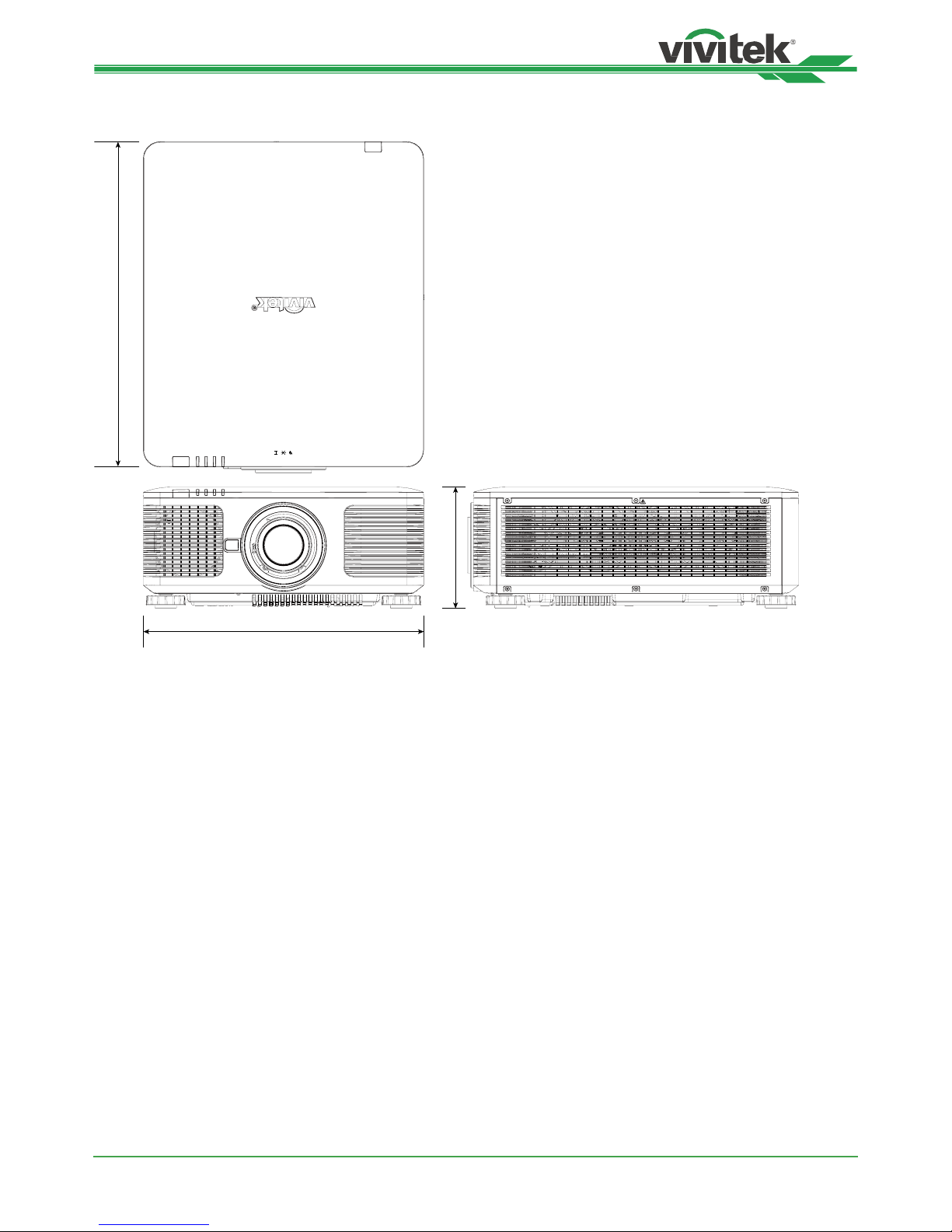
DK8500Z-BK DLP Projector - User Manual
UM8500217EN00
49
Product Dimensions
POWER
STATUS
LIGHT
TEMP.
AVOID EYE CONTACT TO THE LIGHT
580mm
500mm
215mm
Page 50
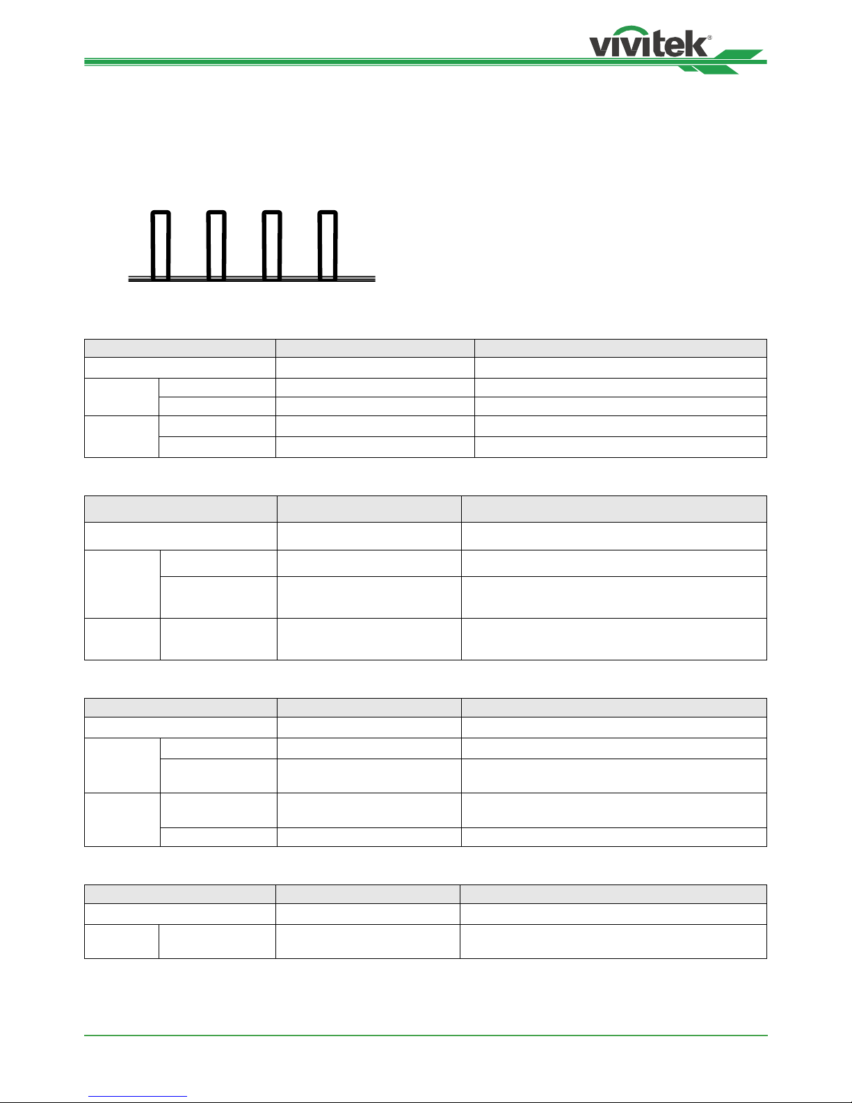
DK8500Z-BK DLP Projector - User Manual
UM8500217EN00
50
LED Indication
Several indicators messages are used to display the current projector status or alert the abnormal message.
POWER
STATUS
LIGHT
TEMP.
Power LED
LED Display Projector status Procedure
Off AC Power is turned off
Flashing
Green Projector is turning on. wait till projector start displaying
Orange Projector is under cooling ~ 5 seconds
On
Red Standby mode
Green Projector is on
Status LED
LED Display Projector status Procedure
Off Normal status
Flashing
Red (Cycles of 1) Cover is opened. Check if the top cabinet is installed properly.
Red (Cycles of 4) Cooling fan error
Contact with your nearest authorized dealer or
service center.
On Red System Error
Contact with your nearest authorized dealer or
service center.
Light Source LED
LED Display Projector status Procedure
Off Light source is off
Flashing
Green Projector is turning on.
Red (Cycles of 6) Light source lit fail
Contact with your nearest authorized dealer or
service center.
On
Red Light source is end-of-life
Contact with your nearest authorized dealer or
service center.
Green Light source is on
Temp LED
LED Display Projector status Procedure
Off Normal status
Flashing Red Over temperature error
Contact with your nearest authorized dealer or
service center.
Page 51

DK8500Z-BK DLP Projector - User Manual
UM8500217EN00
51
Common Problems and Solutions
These guidelines provide tips to deal with problems you may encounter while using the projector. If the problem
remains unsolved, contact your dealer for assistance.
Often the problem is something as simple as a loose connection. Check the following before proceeding to the
problem-specic solutions.
• Use some other electrical device to conrm that the electrical outlet is working.
• Ensure the projector is turned on.
• Ensure all connections are securely attached.
• Ensure the attached device is turned on.
• Ensure a connected PC is not in suspending mode.
• Ensure a connected notebook computer is congured for an external display. (This is usually done by pressing an
Fn-key combination on the notebook.)
Tips for Troubleshooting
• In each problem-specic section, try the steps in the order suggested. This may help you to solve the problem
more quickly.
• Try to pinpoint the problem to avoid replacing non-defective parts.
• For example, if you replace batteries and the problem remains, put the original batteries back and go to the next
step.
• Keep a record of the steps you take when troubleshooting: The information may be useful when calling for
technical support or for passing on to service personnel.
Image Problems
Problem: No image appears on the screen
1. Verify the settings on your notebook or desktop PC.
2. Turn off all equipment and power up again in the correct order.
3. Check if shutter is enabled.
Problem: The image is blurred
1. Adjust the Focus on the projector.
2 Performance Auto Sync on the remote control or projector.
3 Ensure the projection distance is within the specied range.
4. Check that if the projection lens is clean.
Problem: The image is wider at the top or bottom (trapezoid effect)
1. Position the projector so it is as perpendicular to the screen as possible.
2. Use the Keystone function to correct the problem.
Problem: The image is reversed or upside down
Check the Projection Mode setting on the CONTROL->Projection Mode menu.
Problem: The image is streaked
1. Set the Total dots (H Total) and VGA Setup settings on the INPUT menu of the OSD to the default settings.
2. To ensure the problem is not caused by a connected PC’s video card, connect to another computer.
Problem: The image is at with no contrast
1. Adjust the Contrast setting on the PICTURE menu of the OSD.
2. Adjust the Brightness setting on the PICTURE menu of the OSD.
Problem: The color of the projected image does not match the source image.
Adjust the Color temperature and Gamma settings on the PICTURE menu of the OSD.
Page 52

DK8500Z-BK DLP Projector - User Manual
UM8500217EN00
52
Projection Problems
Problem: There is no light from the projector
1. Check that the power cable is securely connected.
2. Ensure the power source is good by testing with another electrical device.
3. Restart the projector in the correct order and check that the Power LED is green.
4. Check if Blank or Shutter function is enabled
Remote Control Problems
Problem: The projector does not respond to the remote control.
1. Direct the remote control towards remote sensor on the projector.
2. Ensure the path between remote and sensor is not obstructed.
3. Check the remote sensor on OSD is turned on.
4. Ensure remote control wire is not plugged in the projector.
5. Turn off any uorescent lights in the room.
6. Check the battery polarity.
7. Replace the batteries.
8. Turn off other Infrared-enabled devices in the vicinity.
9. Have the remote control serviced.
10. Ensure that the remote control code conforms to the projector’s code if universal remote control is used.
11. Check if Projector ID control is enabled and the ID number is correct.
Projection Lens Problems
Problem: The Zoom or Focus adjustment cannot work.
1. Check if the lens is installed properly, improper lens installation may cause to lens cannot work normally.
Please follow the lens installation procedure to check again.
2. Check if Lens Lock function is enabled, locking the lens will disable all of lens adjustment functions.
3. Perform Center Lens function to calibrate the Lens again.
4. Replace the other lens to check the problem if the lens is available.
5. Contact with service center for the details.
Remote communication Problems
Problem: The projector does not respond to Ethernet control
1. Make sure Network Standby is turned on, the communication path is interrupted if it’s turned off(less 0.5W)
2. Check the network conguration in your laptop and projector; refer to Remote Communication manual for more
information.
Having the Projector Serviced
If you are unable to solve the problem, you should have the projector serviced. Pack the projector in the original
carton. Include a description of the problem and a checklist of the steps you took when trying to x the problem. The
information may be useful to the service personnel. Return the projector to the place you purchased it.
Page 53

DK8500Z-BK DLP Projector - User Manual
UM8500217EN00
53
About the Vivitek Support
If you cannot nd solutions from this user guideline, please contact us using the contact information below:
North America
Vivitek Service Center
15700 Don Julian Road, Suite B
City of Industry, CA. 91745
U.S.A
Tel: 855-885-2378 (Toll-Free)
Email: [email protected]
URL: www.vivitekusa.com
Europe and Africa
Vivitek Service & Support
Zandsteen 15
2132 MZ Hoofddorp
The Netherlands
Tel: +31 20 655 0960
Email: [email protected]
URL: www.vivitek.eu
China
Vivitek Service Center
201209, Room 1802, 18/F, Cimic Tower, No.1090, Century Avenue, Pudong, Shanghai
Tel: 400-888-3526 (Toll-Free)
Tel: 021-58360088-142 (Direct)
Email: [email protected]
URL: www.vivitek.com.cn
Asia and Taiwan
VIVITEK after-sales service
Vivitek Corporation, Co., Ltd.
4F., No.186, Ruiguang Rd., Neihu Dist., Taipei City 11491
TEL: 86-28-797-2088
FAX: 86-26-600-2358
E-mail: [email protected]
URL: www.vivitek.com.tw
 Loading...