

Vivotion 8001E Instruction Manual
ELLIPTICAL
TRAINER
INSTRUCTION MANUAL

1
Dear Customers,
We want to thank you for having chosen an Elliptical Trainer and
wish you a lot of fun and success during training.
Please note and follow the enclosed safety and assembly
instructions carefully.
If you have questions please do not hesitate to contact us.
Contents:
1.) Safety Instructions
2.) Exploded Drawing
3.) Parts List
4.) Assembly Instructions
5.) Computer Instructions
6.) Training Instructions

2
SAFETY INSTRUCTION
Before you start training on your home Elliptical Trainer, please
read the instructions carefully. Be sure to keep the instructions for
information, in case of repair and for spare part delivery.
This
elliptical trainer
to a maximum body weight of 150 kg.
Follow the steps of the assembly instructions carefully.
During assembly use only suitable tools and asks for assistance
with assembly if necessary.
is suitable for home use only and tested up
Check that all connecting elements are tight fitting and are in the
correct condition before first use and then again every 1-2 months.
Replace defective components immediately and/ or keep the
equipment out of use until it has been repaired. For repairs, use
only original parts.
In case of repair, please ask your dealer for advice.
Avoid the use of aggressive detergents when cleaning the home
exerciser.
Ensure that training starts only after correct assembly and
inspection of the item.
For all adjustable parts be aware of the maximum positions to
which they can be adjusted/tightened to.
The home exerciser is designed for adults. Please ensure that
children use it only under the supervision of an adult.

3
Ensure that those present are aware of possible hazards, e.g.
movable parts during training.
Consult your physician before starting with any exercise program.
He or she can advise on the kind of training and which impact is
suitable.
WARNING!!!!
INCORRECT/EXCESSIVE TRAINING CAN CAUSE HEALTH
INJURIES.
Please follow the advice for correct training as detailed in training
instructions.
The resistance/work level can be adjusted by turning the
adjustment knob on the handle bar stem.
The safety level of this equipment will only be maintained only if
it is checked regularly using the assembly procedure mentioned in
the assembly instruction sheet.
Please check the tightening knobs regularly for any wear and tear.
4
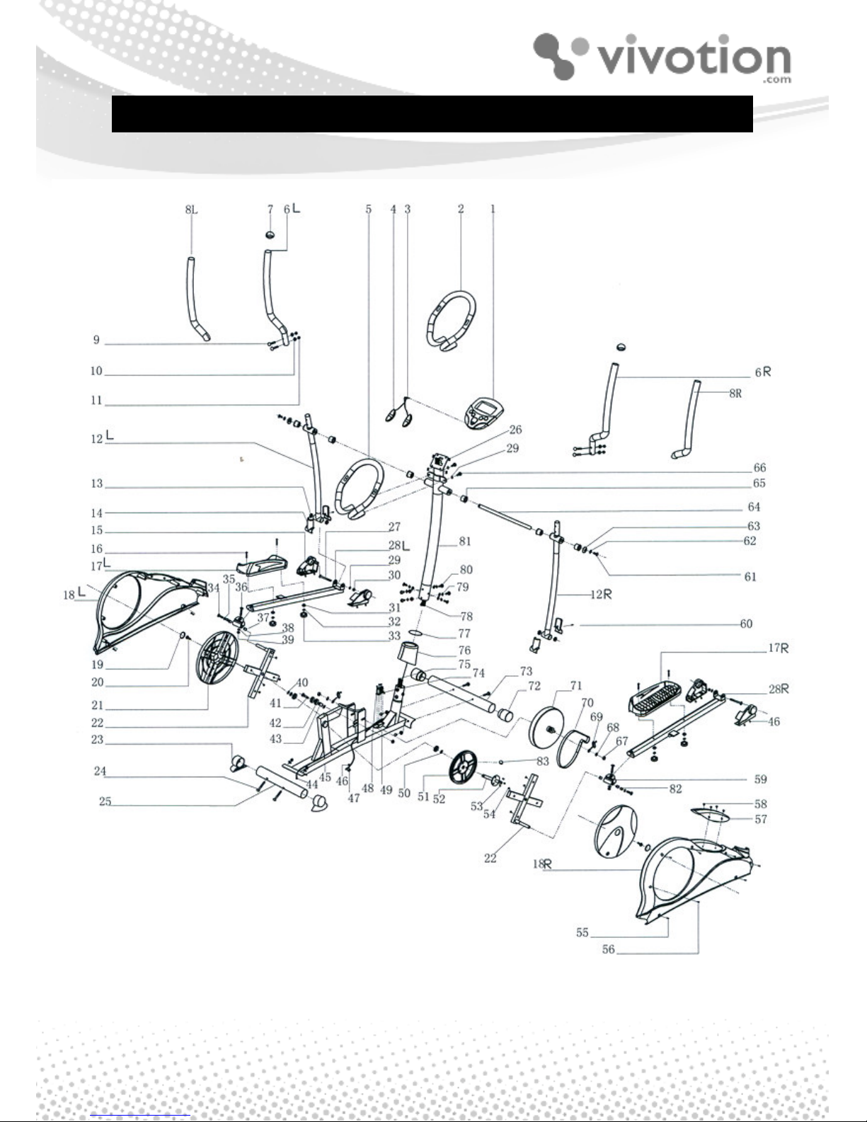
EXPLODED DRAWING

5
PART LIST
Part# Description Quantity
1 Computer 1
2
φφφφ
23*5T*1020L Hand Sponge 1
3 Handle Pulse Cable 1
4 Handle Pulse(L+R) 1 SET
5 Front Handle Bar 1
6 Upper Swing Bar (L+R) 1 SET
7 End Cap 2
8
φφφφ
30*5T*580mml Hand Sponge(L+R) 1 SET
9 M8*40mml Screw 4
10 8*19*1.5mmT Washer 14
11 M8 Nut 8
12 Lower Swing Bar (L+R) 1 SET
13 10*26*8 Tube 4
14 End Cap (Front & Rear) 2
15 End Cap (L+R) 1 SET
16 M6 Screw 4
17 Pedal (L+R) 1 SET
18 Main Cover (L+R) 1 SET
19 Plastic End Cap 2
20 M8*20 Washer 2
21 Chain Cover ( L+R) 1 SET
22 Crank 1
23 Rear End Cap( L+R) 1 SET
24 8*70mml Bolt 4
25 Rear Stabilizer 1
26 5*12 Screw 4
27 10*78mml Screw 2
28 Pedal Bar (L+R) 1 SET
29
φφφφ
10*19*2mmT Washer 4
30 M10 Nut 3
31 6*14*2 Washer 4
32
φφφφ
6 Washer 4
33 M6 Knob 4

6
Part# Description Quantity
34 8*20 Screw 2
35
φφφφ
8*24*2mmT Washer 2
36 M8*48 Screw 2
37 Plastic Tube 4
38 8*16*1.5 Washer 2
39 Nut 2
40 10*19*1.5 Washer 2
41 10*40mml Screw 1
42 Bearing 4
43
φφφφ
10*17*25mml Tube 1
44 Socket 1
45 Main Frame 1
46 M5*10 Screw 9
47 Manual Tension With Cable 1
48 M5*15 Screw 4
49 Socket for motor
1
50 17*22*3 Washer 2
51 Belt Wheel 1
52 Arbor 1
53 M8*15L*1.25 Screw 3
54 M5*15 Screw 8
55 5x15 Screw 4
56 4.5x25 Screw 5
57 Plastic Cover 1
58 M5*10 Screw 4
59 Junction 2
60 M4.5*25 Screw 2
61 M8*20 Screw 2
62 8*16*1.5 Washer 1
63 Plastic Tube 6
64 Axle 1
65 Tube 2
66 M8*20Screw 2
67 Nut 1
68 10*19*2T Washer 1
69 Chain Adjuster 1

7
ASSEMBLY INSTRUCTION
Part# Description Quantity
70 Belt 1
71 Fly Wheel 1
72 Front End Cap(L+R) 1SET
73 Front Stabilizer 1
74 Motor 1
75 Lower Computer Cable 1
76 Plastic Cover 1
77 Lute 1
78 Upper Computer Cable 1
79
φφφφ
8 Spring Washer 6
80 8*20mml*1.25(5mm) Screw 6
81 Upper Support 1
82 Tube 2
83 Magnet 1
STEP 1
45
75
73
8
I. Fasten the front stabiliser (73)
with 2 bolts (24) from the
underside of the stabiliser and
secure it with 2 washers (10)
and 2 cap nuts (11).
II. Fasten the rear stabiliser (25)
with 2 bolts (24) from the
underside of the stabiliser and
secure it with 2 washers (10)
and 2 cap nuts (11).
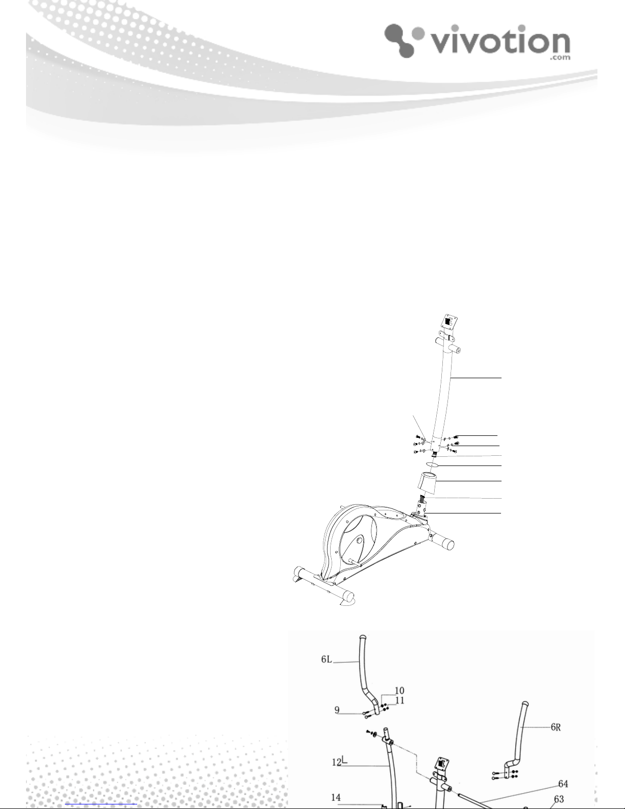
STEP 2
Put the plastic cover (76) into the
upper support (81) and then put the
upper support (81) into the main
frame (45). Secure it with screws
(80) and washers (79).
STEP 3
I. Put the right upper swing bar (6)
into the right lower swing bar
(12) and screw it with bolts (9),
washers (10) and nut (11). Do
the same for the left upper
81
10
80
79
78
77
76
75
45
STEP 2
 Loading...