

Page 1
VIVOTEK Fixed Dome & PTZ Series
Wall-mount Bracket
Installation Guide
Using AM-215 wall-mount bracket
and compatible accessories
Rev. 1.0
IP Surveillance
Page 2
Revision History:
* Rev. 1.0: Initial Release
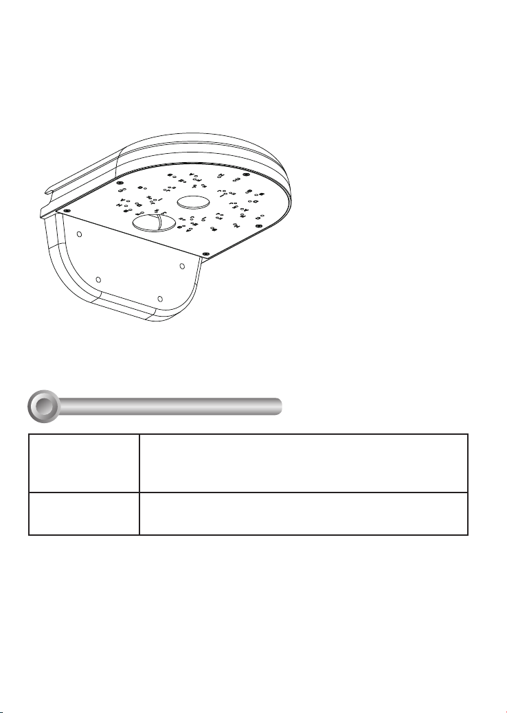
AM-215 Wall-mount Bracket
Compatible VIVOTEK Cameras
I
Fixed Dome series FD8335H, FD8362,FD8363, FD8362E, FD8372, FD8371EV,
PTZ series PD8136
You may also refer to VIVOTEK's website for the list of supported models. Support for other models can
be available through time.
FD8355EHV, FD8365EHV, FD8361, FD8361L, FD8162, FD8163,
FD8135H, FD8161, FD8131, FD8134, FD8131V, FD8134V,
FD8137H, FD8164, FD8137HV, FD8164V, FD8136, FD8151V
2
Page 3
Installation
II
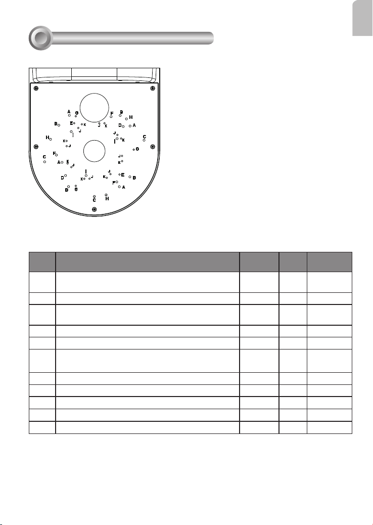
Mounting Hole Denitions
Above are the locations of different groups of mounting holes for matching different
cameras:
Hole
Applicable Cameras Screw No. of
Type
FD8335H, FD8362, FD8363, FD8362E, FD8372,
A
FD8371EV, FD8355EHV, FD8365EHV
FD8361, FD8361L
B
FD8162, FD8163, FD8135H M4X16
C
FD8161
D
FD8131, FD8134
E
FD8131V, FD8134V
F
FD8137H, FD8164
G
FD8137HV, FD8164V
H
PD8136
I
FD8136
J
M4X160 4
M4X10 4
M4X10 21
M4X16 2
M3X6 2
M4X10 3
M3X6 3
M4X10 3
M4X6 3
M3X6 2
K FD8151V M3X6 2
screws
Material
char.
stainless steel
stainless steel
stainless steel
stainless steel,
head diameter
6.8
countersunk
English
3
Page 4
For cabling and conguration details with each network camera, please refer to their
documentation.
Refer to the table below for the description of the included screws:
Screw Description No. of
screws
M4X10 4 Stainless steel, head diameter 6.8
M4X16 2 Stainless steel
M3X6 3 Stainless steel
M4X6 3 Stainless steel, countersunk
Material char.
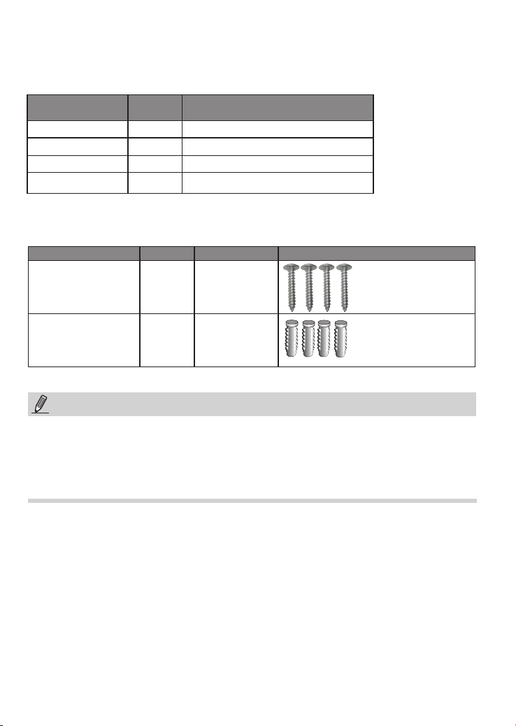
Below are the screws and anchors for installing the bracket to wall:
Screw Description Quantity Applies to
M4X40mm Phillips pan
head
4 Securing the
bracket to wall
Plastic anchors, 3/16" in
diameter, 1" in length
4 Securing the
bracket to wall
NOTE:
1. It is presumed that this wall-mount bracket is installed with a hole drilled on the wall for
routing power lines, DI/DO, and Ethernet cables.
2. Route cables before you secure the wall-mount bracket to a wall.
3. For details on the cable connections with each camera, please refer to their Quick
Installation Guide.
4
Page 5

Wall Mount Installation - FD8136
Below is a general, sample procedure using a wall mount bracket:
1. Locate the position where you want to install the wall mount bracket and camera. Drill
holes on the wall for securing the bracket and for routing the cables.
2. Secure the bracket by hammering anchors into the wall and then fasten screws through
the four mounting holes on the bracket.
3. Route power lines and other cables through the wall and the bracket.
4. Align the camera's mounting holes with 2 of the J holes. Orient the shooting direction
and angles, and then secure the camera to the wall mount bracket as shown below.
IMPORTANT:
The screws and mounting surface must be
M3X6 Screws
Aligned with J holes
able to support a weight of 4 kg.
English
5. Install the dome cover.
5
Page 6
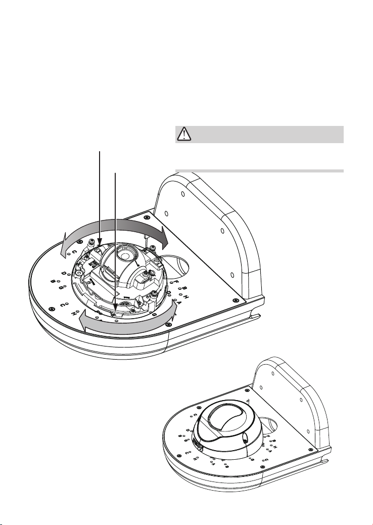
Wall Mount Installation - FD8151V
Below is a general, sample procedure using a wall mount bracket:
1. Locate the position where you want to install the wall mount bracket and camera. Drill
holes on the wall for securing the bracket and for routing the cables.
2. Secure the bracket by hammering anchors into the wall and then fasten screws through
the four mounting holes on the bracket.
3. Route power lines and other cables through the wall and the bracket.
4. Align the camera's mounting holes with 2 of the K holes. Orient the shooting direction
and angles, and then secure the camera to the wall mount bracket as shown below.
IMPORTANT:
Aligned with K holes
M3X6 Screws
The screws and mounting surface must be
able to support a weight of 4 kg.
5. Install the dome cover.
6
Page 7
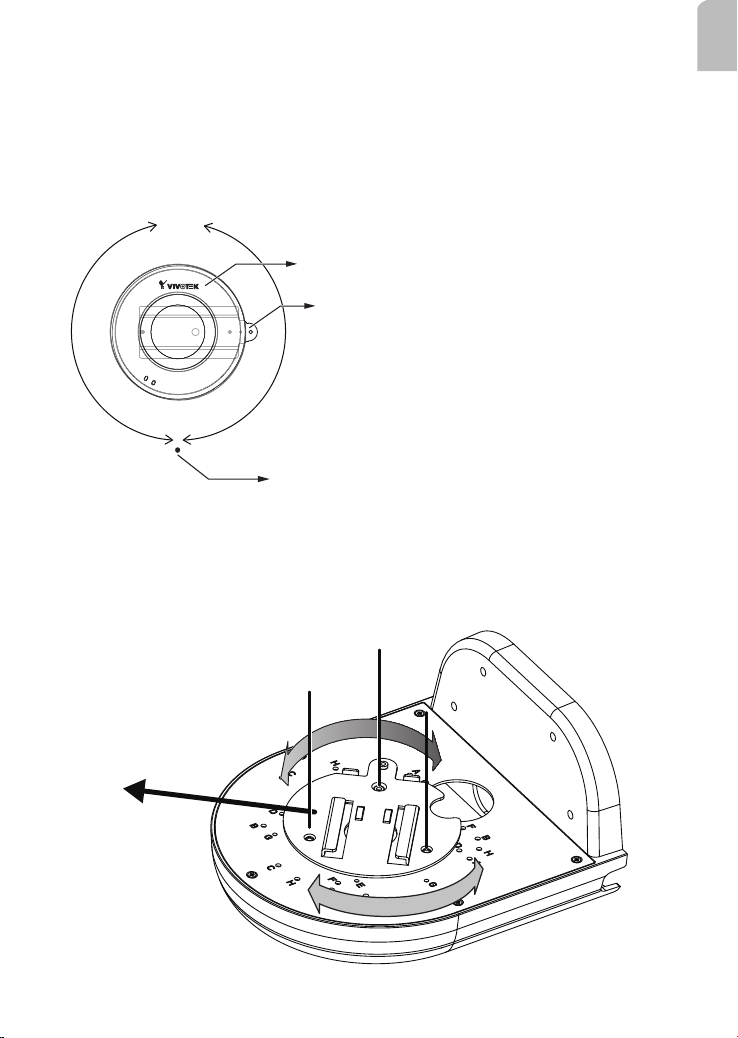
Wall Mount Installation - PD8136
Below is a general, sample procedure using a wall mount bracket:
1. Locate the position where you want to install the wall mount bracket and camera. Drill
holes on the wall for securing the bracket and for routing the cables.
Note that the camera can not perform a 360° continuous pan. Therefore, you should orient
the default 0° towards the direction of your interest.
0°
Logo
Base plate
+180°-180°
Stop point
2. Secure the bracket by hammering anchors into the wall and then fasten screws through
the four mounting holes on the bracket.
3. Route Ethernet and other cables through the wall and the bracket.
4. Align the camera's mounting plate with 3 of the I holes. Orient the shooting direction,
and then secure the mounting plate to the wall mount bracket as shown below.
M4X6 Screws
English
Aligned with I holes
Direction of your interest
7
Page 8
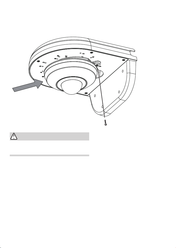
5. Install the camera by sliding it into the mounting bracket. A base plate is attached to the
bottom of the camera.
6. Secure the installation by driving an included screw.
IMPORTANT:
The screws and mounting surface must be
able to support a weight of 4 kg.
8
Page 9
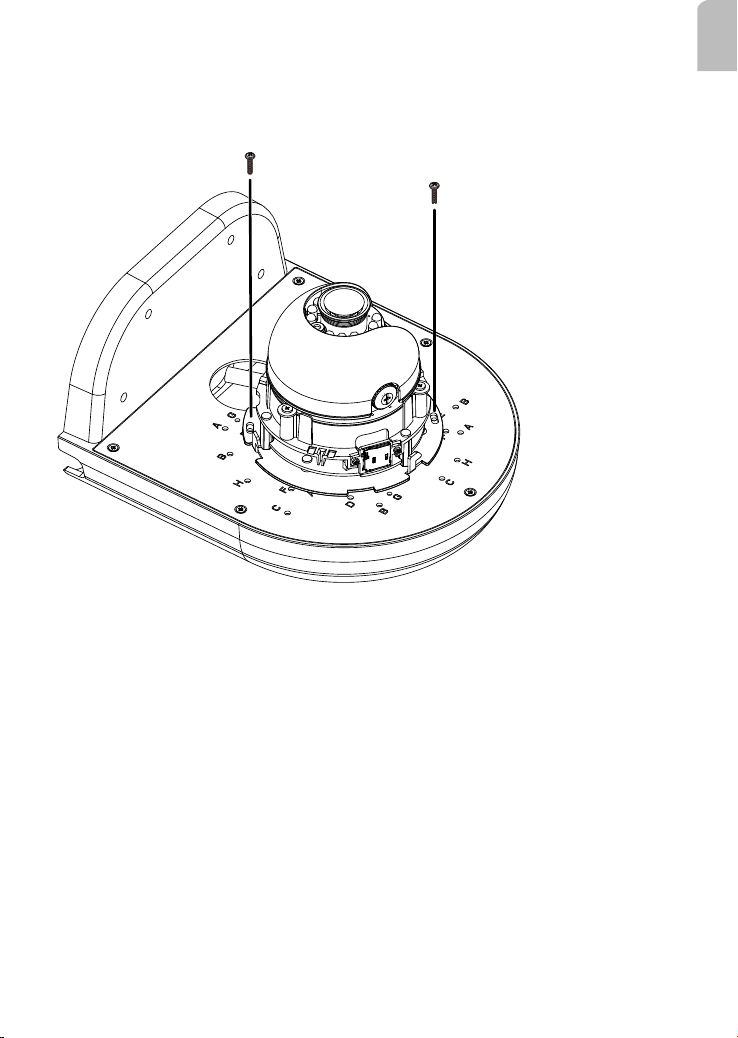
Wall Mount Installation - FD8134
Below is a sample procedure using wall mount bracket and an FD8134:
1. Determine a hard surface wall location, and use the four mounting holes on the wall
mount bracket to mark the positions where holes will be drilled to secure the bracket.
M3X6 Screws
E holes
2. Drill holes on the wall for passing cables and for securing the wall mount bracket.
3. Secure the bracket by hammering anchors into the wall and then fasten screws.
4. Route power lines and other cables through the bracket and wall.
5. Secure camera to the wall mount bracket using the E holes and M3x6 screws.
6. Proceed with initial setup such as enabling network access, focus tuning, or zooming.
When done, secure the outer dome cover.
English
9
Page 10
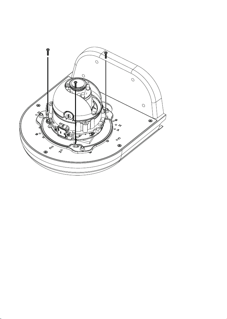
Wall Mount Installation - FD8134V
Below is a sample procedure using wall mount bracket and an FD8134V:
1. Determine a hard surface wall location, and use the four mounting holes on the wall
mount bracket to mark the positions where holes will be drilled to secure the bracket.
M4X10 Screws
F holes
2. Drill holes on the wall for passing cables and for securing the wall mount bracket.
3. Secure the bracket by hammering anchors into the wall and then fasten screws.
4. Route power lines and other cables through the bracket and wall.
5. Secure camera to the wall mount bracket using the F holes and M4x10 screws.
6. Proceed with initial setup such as enabling network access, focus tuning, or zooming.
When done, secure the outer dome cover.
10
Page 11
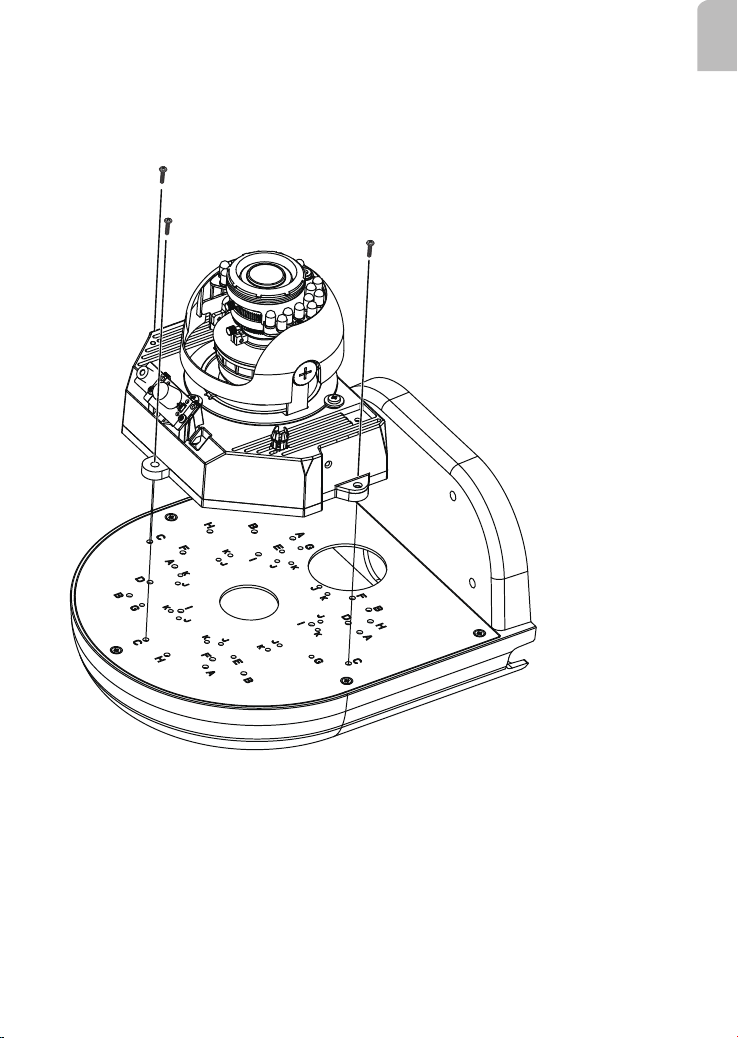
Wall Mount Installation - FD8162, FD8135H, or FD8163
Below is a sample procedure using wall mount bracket and an FD8162:
1. Determine a hard surface wall location, and use the four mounting holes on the bracket
to mark the positions where holes will be drilled to secure the bracket.
M4X16
English
M4X10
M4X16
C* holes
2. Drill holes on the wall for securing the bracket and for routing cables.
3. Route cables through the wall and bracket.
4. Secure the wall mount bracket to the wall using the included screws and plastic
anchors.
5. Rotate the adaptor ring to match the camera lens orientation your prefer, e.g., to the
front or to the left. Secure the adaptor ring to bracket using the M4X10 screws to the C
holes on the bracket.
11
Page 12
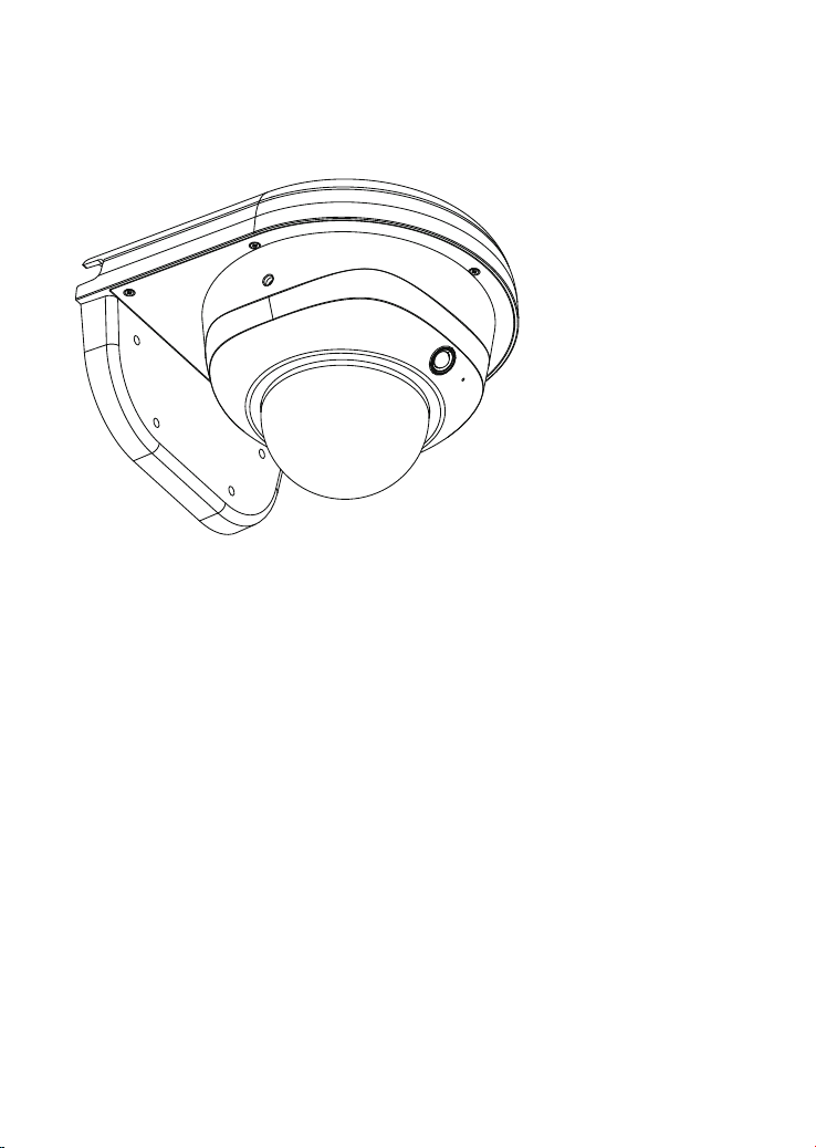
6. Connect power lines and cables to the camera.
7. Proceed with initial setup such as enabling network access, focus tuning, or zooming.
When done, secure the outer dome cover.
12
Page 13
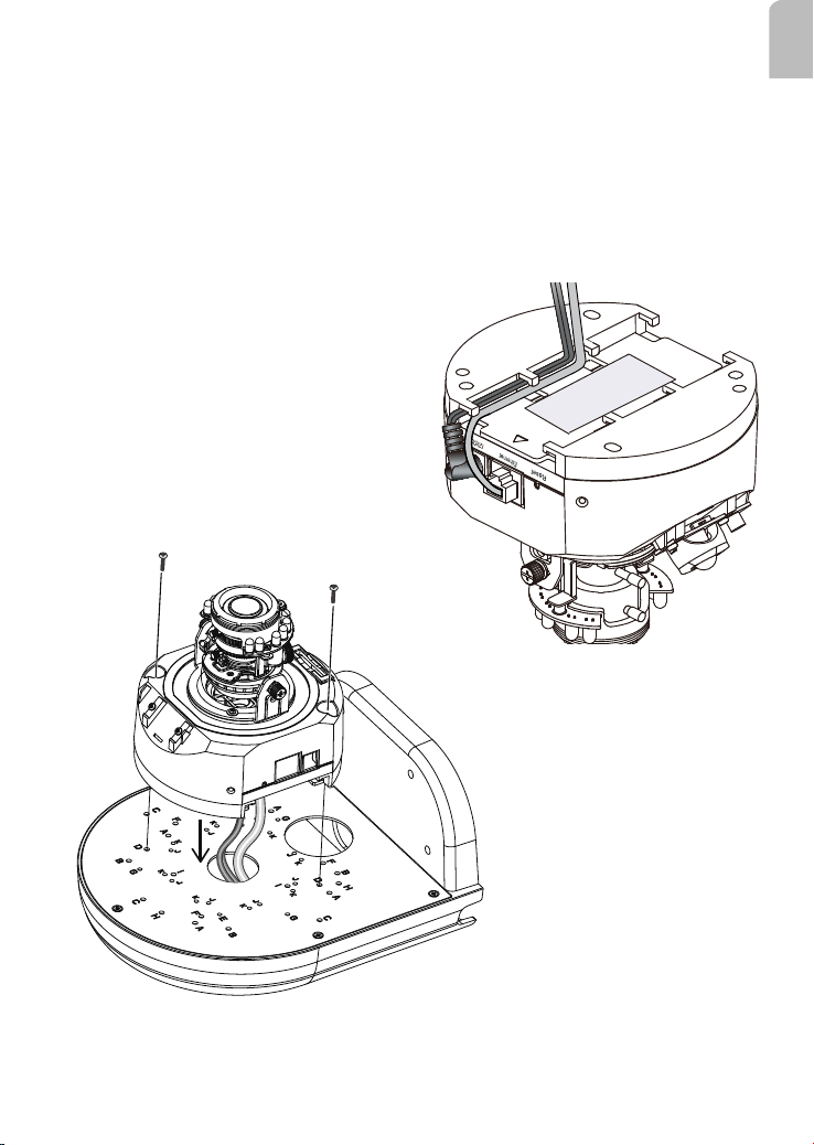
Wall Mount Installation - FD8161
Below is a general, sample procedure using a wall mount bracket with the FD8161
camera:
1. Locate the position where you want to install the wall mount bracket and camera. Drill
holes on the wall for securing the bracket and for routing cables.
2. You can route cables through the hole in the center of the bracket and the space
beneath the camera.
3. Secure the wall mount bracket to the wall using the included plastic anchors and
screws.
Cable routing path
M4x16 scews
English
D holes
4. Attach the camera to the bracket using 2 M4X16 screws.
5. Connect cables and you may now begin the initial connection and conguration.
13
Page 14
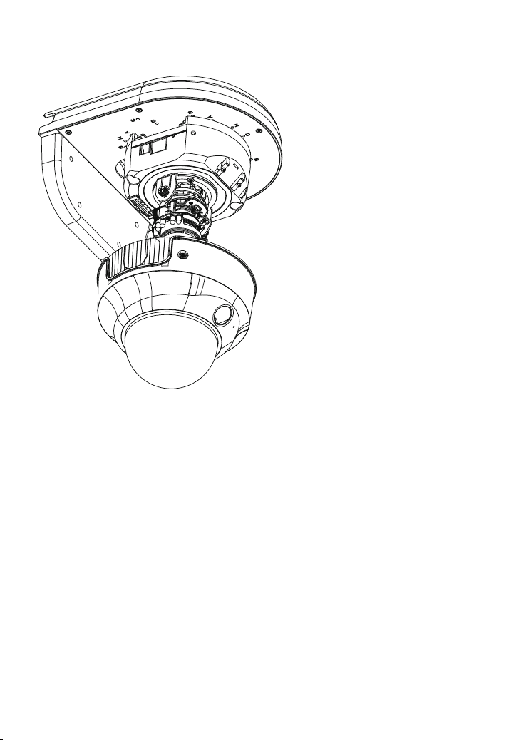
6. Attach dome cover to the camera.
14
Page 15
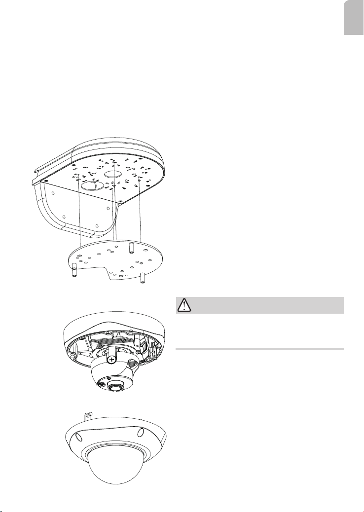
Wall Mount Installation - FD8362E / 8335H / 8372
Below is a general, sample procedure using a wall mount bracket with the FD8362E,
FD8335H, and FD8372 cameras:
1. Locate the position where you want to install the wall mount bracket and camera. Drill
holes on the wall for securing the bracket and for routing cables.
2. You can route cables through the hole in the center of the bracket.
3. Secure the wall mount bracket to the wall using the included plastic anchors and
screws.
4. Attach the camera's mounting plate (which comes with the outdoor series cameras) to
the bracket using 4 M4X10 screws, by fastening it to the A holes. Orient the mounting
plate so that cables can pass through the cut-out and the opening on the AM-215.
5. Connect cables and you may now begin the
initial connection and conguration.
6. Install the dome cover.
IMPORTANT:
English
The screws and mounting surface must be able
to support a weight of 5 kg.
15
Page 16
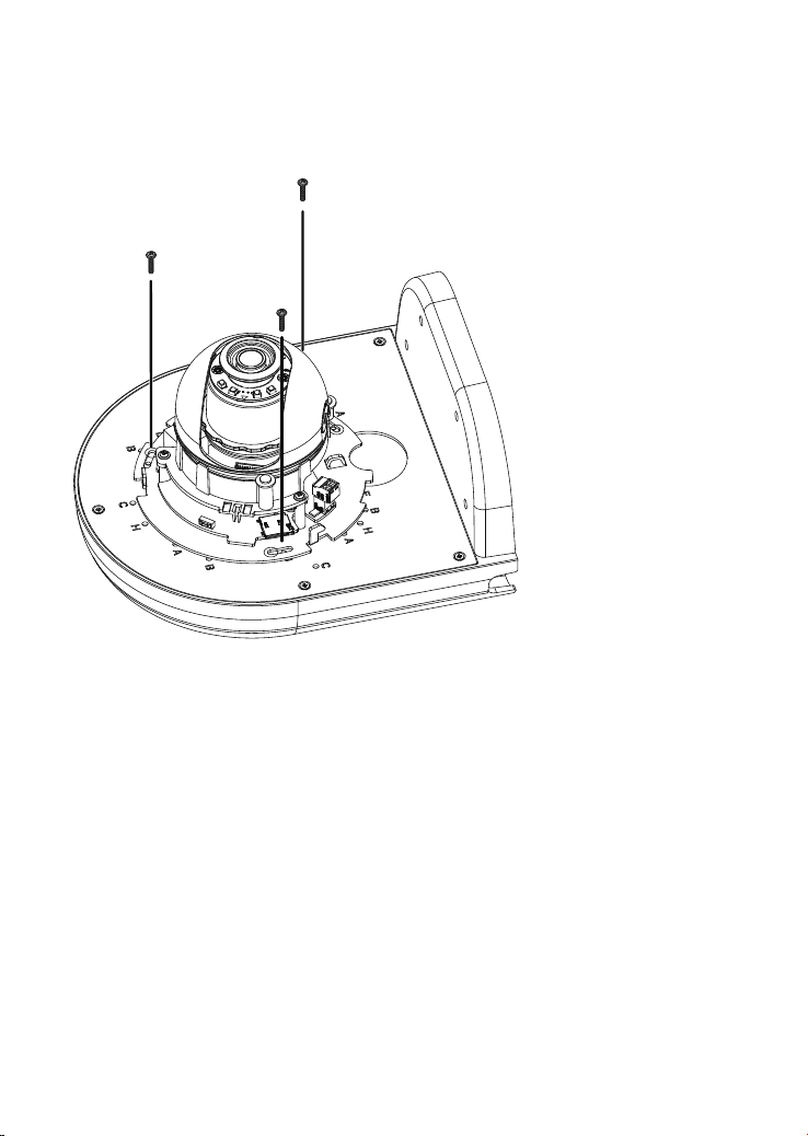
Wall Mount Installation - FD8164
Below is a sample procedure using wall mount bracket and an FD8164:
1. Determine a hard surface wall location, and use the four mounting holes on the wall
mount bracket to mark the positions where holes will be drilled to secure the bracket.
M3X6 Screws
G holes
2. Drill holes on the wall for passing cables and for securing the wall mount bracket.
3. Secure the bracket by hammering anchors into the wall and then fasten screws.
4. Route power lines and other cables through the bracket and wall.
5. Secure camera to the wall mount bracket using the G holes and M3x6 screws.
6. Proceed with initial setup such as enabling network access, focus tuning, or zooming.
When done, secure the outer dome cover.
16
Page 17
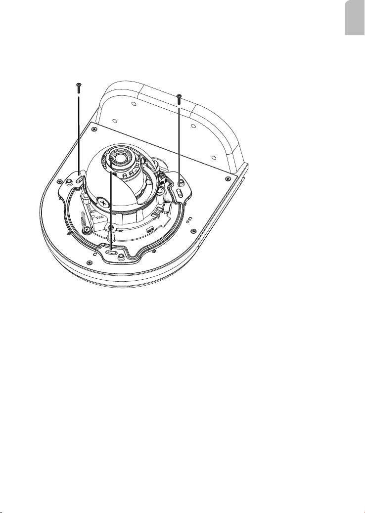
Wall Mount Installation - FD8164V
Below is a sample procedure using wall mount bracket and an FD8164V:
1. Determine a hard surface wall location, and use the four mounting holes on the wall
mount bracket to mark the positions where holes will be drilled to secure the bracket.
M4X10 Screws
H holes
2. Drill holes on the wall for passing cables and for securing the wall mount bracket.
3. Secure the bracket by hammering anchors into the wall and then fasten screws.
4. Route power lines and other cables through the bracket and wall.
5. Secure camera to the wall mount bracket using the H holes and M4x10 screws.
6. Proceed with initial setup such as enabling network access, focus tuning, or zooming.
When done, secure the outer dome cover.
English
17
Page 18
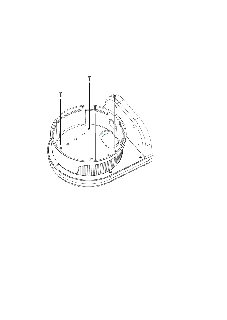
Wall Mount Installation - FD8361 & FD8361L
Below is a general, sample procedure using a wall mount bracket with the FD8361 and
FD8361L cameras:
1. Locate the position where you want to install the wall mount bracket and camera. Drill
holes on the wall for securing the bracket.
2. Secure the wall mount bracket to the wall using the included plastic anchors and
screws.
3. Align and secure the camera's bowl-like bottom base to the bracket using 4 M4X10
screws. Use the B holes and align the opening for routing the cables. See the drawings
below.
M4X10
B* holes
18
Page 19
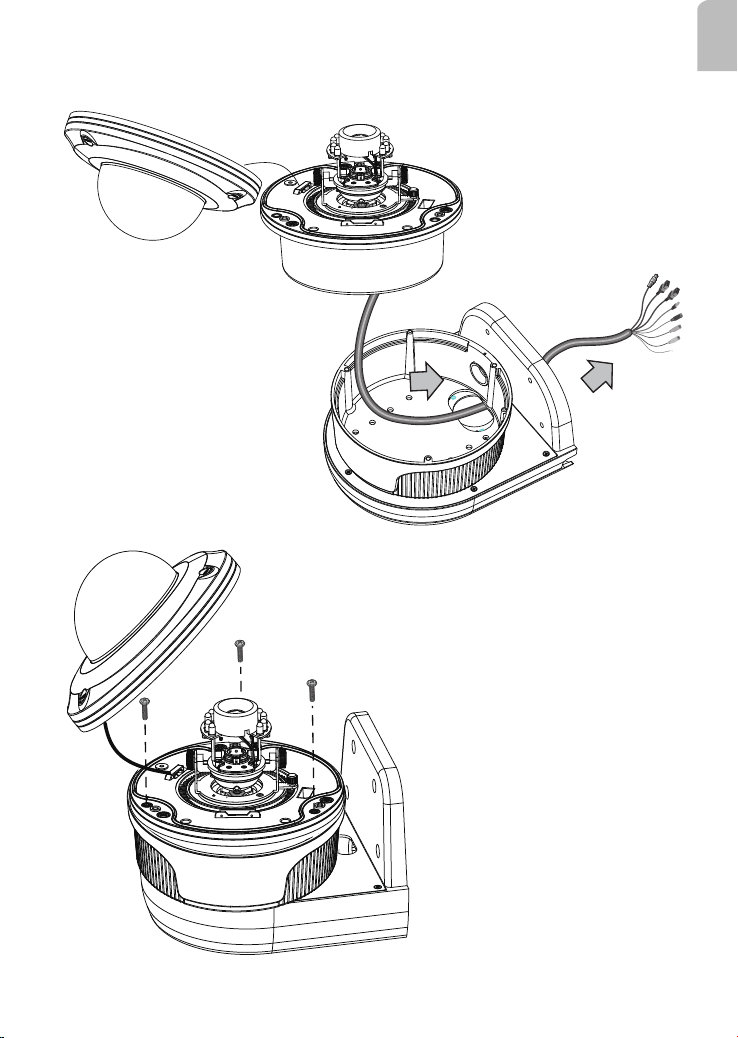
4. Pass the combo cable through the routing hole, and then t the camera into the bottom
base. You may need to pull the cable and squeeze the camera into the bottom base.
5. Fasten the camera to the bottom base
using 3 included screws.
English
19
 Loading...