

Page 1
Outdoor Wireless Access Point Series
4 5
1
2
3
8
6
7 9
10
Outdoor Wireless Access Point Series
Outdoor Wireless Access Point SeriesOutdoor Wireless Access Point Series
Quick Installation Guide
Quick Installation Guide
Quick Installation GuideQuick Installation Guide
1. Product and Parts
1. Product and Parts
1. Product and Parts1. Product and Parts
500AG/600AG/3300AG
500AG/600AG/3300AG
500AG/600AG/3300AG500AG/600AG/3300AG
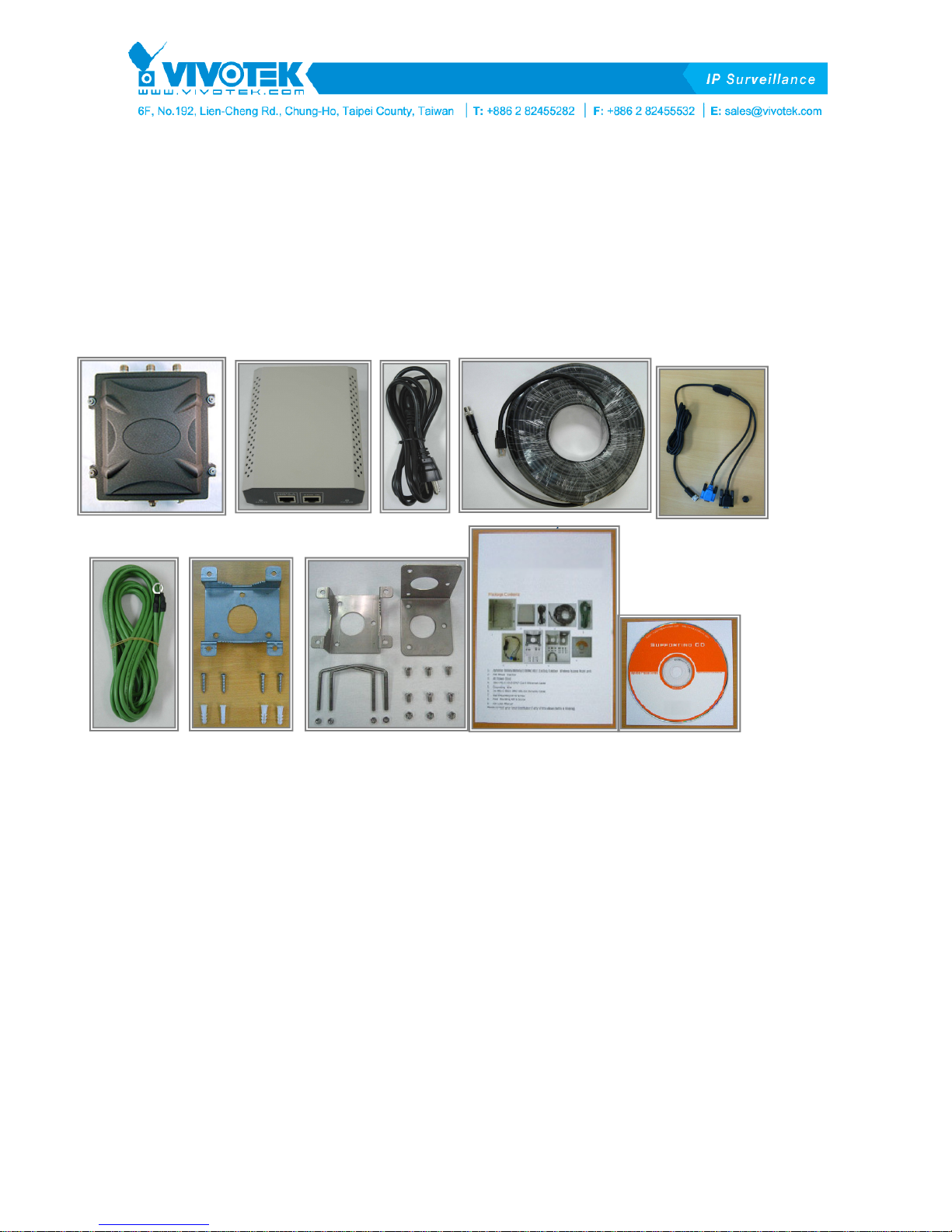
1. 500AG/600AG/3300AG 802.11a/b/g Outdoor Wireless Access Point unit
2. PoE Power Injector (Input AC 90~240V, Output DC 48V/1A)
3. AC Power Cord
4. 30m MIL-C-5015 IP67 Cat-5 Ethernet Cable
5. 2m MIL-C-5015 IP67 RS-232 Console Cable
6. Grounding Wire
7. Wall Mounting Kit & Screw
8. Mast Mounting Kit & Screw
9. Quick Installation Guide. (or download from ftp server)
10. CD: User Manual. (or download from ftp server)
Please contact your local distributor/reseller if any of the above items is missing.
1
V1.0
Page 2
2.
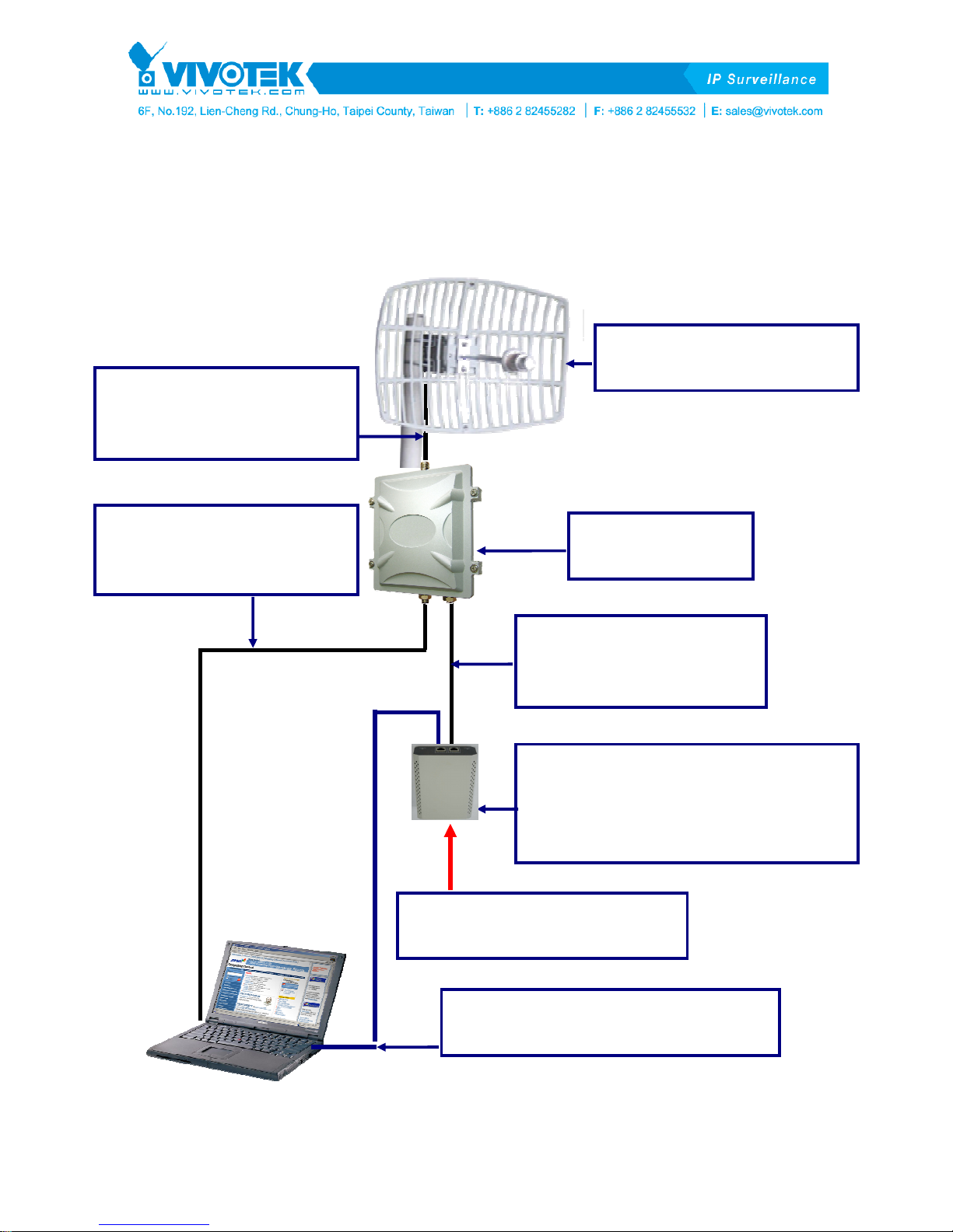
2. Outdoor Access Point Install Diagram
Outdoor Access Point Install Diagram
2. 2.
Outdoor Access Point Install DiagramOutdoor Access Point Install Diagram
1.5M CFD-400 RF Cable
N-Type Male to Male
Antenna Connector Cable
2.4GHz or 5.8GHz Antenna
2M IP67 RS-232
Serial Connector Cable
(For Setting AP)
500AG Wireless
Access Point
30M IP67 Cat-5
Waterproof Ethernet
Connector Cable (Power)
PoE (Power over Ethernet) Adapter
Input AC 90~240V
Output DC 48V/1A for AP
(Integrate Power and Data)
AC 90~240V Power Code Cable
(Input AC Power)
2
V1.0
Cat-5 (RJ-45) Ethernet Cable
(Input Digital Data/Video/Voice)
Page 3

3.
3. AP Configuration with SMT User Interface
AP Configuration with SMT User Interface
3. 3.
AP Configuration with SMT User InterfaceAP Configuration with SMT User Interface
3333----1.
1. Conf
Configuring AP
1.1.
ConfConf
STEP
STEP––––1111.... Power on the AP
STEPSTEP
1.Connect power supply to PoE injector with the AC power cord provided as shown in the above
iguring AP with
iguring AP iguring AP
Power on the AP
Power on the APPower on the AP
with Telnet
with with
Telnet
TelnetTelnet
diagram. The yellow POWER
2.Connect The AP to POWE
Cable provided. The red ACTIVE
3.Connect DATA IN
with.
STEP
STEP––––2222. Verify IP address setting
STEPSTEP
Configure the network settings on your PC to obtain an IP address. Computer uses IP addresses to
communicate with each other across a network, such as a LAN. The default IP address of the AP is
192.168.1.1
192.168.1.1 so the PC needs to be set in the same net scope to access AP with Telnet.
192.168.1.1192.168.1.1
1.Go to Control Panel
2.Right click Local
3.Select TCP/IP
4.Click the IP Address
192.168.1.
192.168.1.2222 to 192.168.1.254
192.168.1.192.168.1.
Mask
Mask, then click OK
MaskMask
STEP
STEP––––3333.
STEPSTEP
DATA IN port on the PoE injector with Ethernet cable to the LAN that the AP associates
DATA INDATA IN
. Verify IP address setting
. Verify IP address setting. Verify IP address setting
Control Panel of your PC and double-click Network
Control PanelControl Panel
Local Area
Local Local
TCP/IP for the applicable Ethernet adapter and click Prope
TCP/IPTCP/IP
IP Address tab page, select USE the following IP address
IP AddressIP Address
. Connect the AP by
Connect the AP by telnet
. .
Connect the AP by Connect the AP by
POWER LED on the PoE will be on when the PoE has adequate power supply.
POWERPOWER
POWER & DATA OUT
POWEPOWE
Area Connection
AreaArea
92.168.1.254 (192.168.1.1 is for the AP) for IP Address
92.168.1.25492.168.1.254
OK button.
OKOK
R & DATA OUT port on the PoE with MIL-C-5015 IP67 Cat-5 Ethernet
R & DATA OUTR & DATA OUT
ACTIVE LED indicates if the AP has successfully powered-on.
ACTIVEACTIVE
The default IP address of the AP is
The default IP address of the AP is The default IP address of the AP is
Network CCCConnections
Network Network
Connection and select Properties
ConnectionConnection
telnet
telnettelnet
Properties.
PropertiesProperties
USE the following IP address, type an address between
USE the following IP addressUSE the following IP address
onnections icon.
onnectionsonnections
Properties
PropePrope
IP Address and 255.255.255.0
IP AddressIP Address
rties.
rtiesrties
255.255.255.0 for Subnet
255.255.255.0255.255.255.0
Subnet
Subnet Subnet
After having the correct connection, start the telnet session to 192.168.1.1
““““0000
0000”””” and press ENTER on your keyboard to enter the main menu. The system menu tree (SMT) will
00000000
appear on your terminal software as shown below. ((((Note:
Please refer to the user manual for detailed description of each selection item.
3
V1.0
192.168.1.1. Enter the default password
192.168.1.1192.168.1.1
Note: The Web UI is ID: admin / PW: password
Note: Note:
The Web UI is ID: admin / PW: password....))))
The Web UI is ID: admin / PW: passwordThe Web UI is ID: admin / PW: password
Enter the default password
Enter the default password Enter the default password
Page 4

3333----2.
2. Configuring AP
Configuring AP with
2.2.
Configuring AP Configuring AP
Alternatively, the AP can be configured via console and serial port on your PC.
1.Connect power supply to PoE injector with the AC power cord provided, and connect The AP to
POWER & DATA OUT
POWER & DATA OUT port on the PoE with MIL-C-5015 IP67 Cat-5 Ethernet Cable provided as
POWER & DATA OUTPOWER & DATA OUT
with CCCConsole
with with
onsole
onsoleonsole
shown in the connection diagram. Both POWER
is properly powered-on.
2.Connect the AP and the PC with MIL-C-5015 IP67 RS-232 Console Cable with 115200bps
connector (the black color RS232 connector) provided.
3.Adjust the baud rate of your terminal software to 115200bps (128kbps).
4.Set the flow control to N/A.
5.Connect the AP from terminal software.
6.Enter the default password “0000
If the connection is correct, the main menu of The system menu tree (SMT) will appear on your
terminal software. ((((Note:
4.
4. Outdoor Installation
Outdoor Installation
4. 4.
Outdoor InstallationOutdoor Installation
Note: The Web UI is ID: admin / PW: password
Note: Note:
0000” and press enter on your keyboard to into the main menu of SMT.
00000000
The Web UI is ID: admin / PW: password....))))
The Web UI is ID: admin / PW: passwordThe Web UI is ID: admin / PW: password
POWER and ACTIVE
POWERPOWER
ACTIVE LED on the PoE will be on when The AP
ACTIVEACTIVE
Mounting Kits
4
V1.0
Page 5

5. Waterproof Installation and Protect Device
5. Waterproof Installation and Protect Device
5. Waterproof Installation and Protect Device5. Waterproof Installation and Protect Device
Most of the problems of outdoor models are from the connector
connections that loosen over time due to vibration or other forces, even
allowing moisture to penetrate the connector and seriously affecting the
data and radio signal transmit. The following recommendation is used for
all outdoor installation to be waterproofed.
Step1: Fasten all connectors securely together.
Step2: Tightly wrap two layers of self-bonding insulating tape forward and
backward over the physical connection extending 2 inches beyond the
connectors or the end of heat-shrinkable tubing on the RF coaxial cable or
omni- antenna connector, and overlapping the tape on each turn.
Step3: Recover again by tape more cover 1.5cm.
5
V1.0
 Loading...