

Page 1
ViVOpay
®
8100e User Guide
Revision 1.0
Part Number: 631-0081-00 August 2011
ViVOtech, Inc. 451 El Camino Real, Santa Clara, CA 95050 Ph: (408) 248-7001
Email: [email protected] URL: www.vivotech.com
Page 2

Copyright© 2011, ViVOtech® Inc. All rights reserved.
ViVOtech, Inc.
451 El Camino Real
Santa Clara, CA 95050
Written and designed at ViVOtech, Inc.
This document, as well as the hardware and software it describes, is furnished under license and may only be used
in accordance with the terms of such license. The content of this paper is furnished for informationa l use, subject to
change without notice, and not to be construed as a commitment by ViVOtech, Inc. ViVOtech, Inc. assumes no
responsibility or liability for any errors or inaccuracies that may appear in this document.
Except as permitted by such license, no part of this publication may be reproduced or transmitted by electronic,
mechanical, recorded, or any other method, or translated into another language or language form without the
express written consent of ViVOtech, Inc. ViVOtech, ViVOpay, ViVOwallet, ViVOcard, ViVOplatform, ViVOnfc,
ViVOapps, ViVOtag, ViVOpos, mTouch, mLoyalty, mPromotion and mPrepaid are trademarks or registered trademarks of ViVOtech Inc. Other trademarks are the property of the respective owner.
Warranty Disclaimer: The services and hardware are provided "as is" and "as-available," and the use of these services and hardware is at the user’s own risk. ViVOtech does not make, and hereby disclaims, any and all other
express or implied warranties, including, but not limited to warranties of merchantability, title, fitness for a p articular
purpose, and any warranties arising from any course of dealing, usage, or trade practice. ViVOtech does not warrant that the services or hardware will be uninterrupted, error-free, or completely secure.
August 2011
Page 3

Table of Contents
Chapter 1
Getting Started . . . . . . . . . . . . . . . . . . . . . . . . . . . . . . . . . . . . . . . . . . . . . 1
Overview . . . . . . . . . . . . . . . . . . . . . . . . . . . . . . . . . . . . . . . . . . . . . . . . . . . . . 1
Features . . . . . . . . . . . . . . . . . . . . . . . . . . . . . . . . . . . . . . . . . . . . . . . . 1
Options . . . . . . . . . . . . . . . . . . . . . . . . . . . . . . . . . . . . . . . . . . . . . . . . . 1
Unpacking the ViVOpay 8100e . . . . . . . . . . . . . . . . . . . . . . . . . . . . . . . . . . . . 2
Accessories . . . . . . . . . . . . . . . . . . . . . . . . . . . . . . . . . . . . . . . . . . . . . . . . . . . 2
Chapter 2
Installing the ViVOpay 8100e . . . . . . . . . . . . . . . . . . . . . . . . . . . . . . . . . . 3
Overview . . . . . . . . . . . . . . . . . . . . . . . . . . . . . . . . . . . . . . . . . . . . . . . . . . . . . 3
Site Planning . . . . . . . . . . . . . . . . . . . . . . . . . . . . . . . . . . . . . . . . . . . . . . . . . . 3
PCI PED Compliance . . . . . . . . . . . . . . . . . . . . . . . . . . . . . . . . . . . . . . 3
PCI Compliance Guidelines . . . . . . . . . . . . . . . . . . . . . . . . . . . . . . . 3
Radio Frequency Interference . . . . . . . . . . . . . . . . . . . . . . . . . . . . . . . 4
Installing the ViVOpay 8100e . . . . . . . . . . . . . . . . . . . . . . . . . . . . . . . . . . . . . 5
Connector Access . . . . . . . . . . . . . . . . . . . . . . . . . . . . . . . . . . . . . . . . . 5
Install a SAM Card . . . . . . . . . . . . . . . . . . . . . . . . . . . . . . . . . . . . . . . . 6
Connect Data and Power . . . . . . . . . . . . . . . . . . . . . . . . . . . . . . . . . 7
Mount the ViVOpay 8100e to a Surface . . . . . . . . . . . . . . . . . . . . . . . . 8
Mounting the Wedge Bracket . . . . . . . . . . . . . . . . . . . . . . . . . . . . . . . . 9
Testing the Installation . . . . . . . . . . . . . . . . . . . . . . . . . . . . . . . . . . . . . . . . . 10
Chapter 3
Troubleshooting and Maintenance . . . . . . . . . . . . . . . . . . . . . . . . . . . . 11
Troubleshooting . . . . . . . . . . . . . . . . . . . . . . . . . . . . . . . . . . . . . . . . . . . . . . 11
Onboard Diagnostics . . . . . . . . . . . . . . . . . . . . . . . . . . . . . . . . . . . . . 12
Accessing the OBD Tests . . . . . . . . . . . . . . . . . . . . . . . . . . . . . . . . 12
Test Results Summary . . . . . . . . . . . . . . . . . . . . . . . . . . . . . . . . . . 13
Test All . . . . . . . . . . . . . . . . . . . . . . . . . . . . . . . . . . . . . . . . . . . . . . 14
LCD Test . . . . . . . . . . . . . . . . . . . . . . . . . . . . . . . . . . . . . . . . . . . . 14
Touch Screen Test . . . . . . . . . . . . . . . . . . . . . . . . . . . . . . . . . . . . . 14
Keypad Test . . . . . . . . . . . . . . . . . . . . . . . . . . . . . . . . . . . . . . . . . . 14
LED Test . . . . . . . . . . . . . . . . . . . . . . . . . . . . . . . . . . . . . . . . . . . . . 15
Tone Test . . . . . . . . . . . . . . . . . . . . . . . . . . . . . . . . . . . . . . . . . . . . 15
Magstripe Test . . . . . . . . . . . . . . . . . . . . . . . . . . . . . . . . . . . . . . . . 16
RFID and Antenna Test . . . . . . . . . . . . . . . . . . . . . . . . . . . . . . . . . 16
Security Elements Test . . . . . . . . . . . . . . . . . . . . . . . . . . . . . . . . . . 16
Contact Interface Tests . . . . . . . . . . . . . . . . . . . . . . . . . . . . . . . . . 17
ViVOpay 8100e User Guide 1
Page 4

Maintenance . . . . . . . . . . . . . . . . . . . . . . . . . . . . . . . . . . . . . . . . . . . . . . . . . .17
Upgrading the Firmware . . . . . . . . . . . . . . . . . . . . . . . . . . . . . . . . . . . 17
Appendix A
Specifications . . . . . . . . . . . . . . . . . . . . . . . . . . . . . . . . . . . . . . . . . . . . 19
ViVOpay 8100e Specifications . . . . . . . . . . . . . . . . . . . . . . . . . . . . . . . . . . . .19
Regulatory Compliance . . . . . . . . . . . . . . . . . . . . . . . . . . . . . . . . . . . . . . . . .20
FCC Part 15 Class B Equipment . . . . . . . . . . . . . . . . . . . . . . . . . . . . 20
FCC Information for User . . . . . . . . . . . . . . . . . . . . . . . . . . . . . . . . . . 20
Industry Canada Class B Equipment . . . . . . . . . . . . . . . . . . . . . . . . . 20
Industry Canada Information for User . . . . . . . . . . . . . . . . . . . . . . . . 20
Glossary . . . . . . . . . . . . . . . . . . . . . . . . . . . . . . . . . . . . . . . . . . . . . . . . 21
ViVOpay 8100e User Guide 2
Page 5

Overview
Chapter 1
Getting Started
The ViVOpay 8100e seamlessly integrates with existing POS systems and requires minimal counter
space at checkout stands. The ViVOpay 8100e is a PCI-certified counter-top NFC contactless reader
with integrated display, MSR, function keys, PIN pad and optional contact card reader. This device
features serial RS-232 and USB 2.0 communications to POS systems as well as an Ethernet port.
The ViVOpay 8100e complies with ISO/IEC 18092 and supports the full peer-to-peer NFC feature
set.
ViVOpay 8100e is certified for the following contactless payment applications:
• PayPass ISO/IEC 144443
• MasterCard PayPass Magstripe v3.3
• Visa payWave MSD v2.0.2
• American Express, ExpressPay v1.0
• Discover Zip v1.0
• Mifare ePurse (Passthrough)
• ViVOcard 1 and 2
Features
Options
ViVOpay 8100e also fully supports
This document assumes that users are familiar with their host POS systems and all related functions.
The following features are supported:
• PCI certified
• ISO14443 type A/B and Mifare based contactless payment transactions
• ISO 18092 support for peer-to-peer NFC devices and smartphones
• PIN entry for PIN debit transactions
• Three-track magnetic stripe card transactions
• SAM card slot
• Contact card slot
• 10 Base-T Ethernet port
The following options are available:
• Second SAM slot
This User Guide provides information on all options.
PIN debit and credit
magnetic stripe applications.
ViVOpay 8100e User Guide 1
Page 6
Unpacking the ViVOpay 8100e
The ViVOpay 8100e requires a data cable and a power supply. V erify that you have all the required
components for the installation.
ViVOpay 8100e (P/N 540-2901-XX)
Data cable (varies by POS and length)
• Serial Data Cable (P/N 220-2463-0X)
• USB Data Cable (P/N 220-2462-0X)
These cables are recommended and approved by
ViVOtech to comply with FCC rules and regulations.
Getting S tarted
Accessories
Power supply, if required
• US/North America (P/N 140-2035-00)
• Europe (P/N 140-2035-01)
This power supply recommended and approved by
ViVOtech to comply with FCC rules and regulations.
You may also need the following:
• Four M3 screws
If you want to secure the reader to a surface, you need four M3 screws of the appropriate length
(not supplied).
• Contactless test card (ViVOcard Contactless Test Card P/N 241-0015-03)
The ViVOtech data cables and power supply are specifically designed to meet FCC requirements. If
you are using other cables or power supply, you may be required to install ferrites. For your free
ferrite core kit with installation instructions, please contact ViVOtech support.
The following accessories are available for the ViVOpay 8100e.
Part Number Description
520-2370-00 Wedge Bracket Kit
ViVOpay 8100e User Guide 2
Page 7

Overview
Before you connect and mount the ViVOpay 8100e, you should plan the installation to conform to
PCI requirements and minimize radio frequency interference. Once you have determined the
location and mounting of the ViVOpay 8100e, you can connect it to power and the POS terminal.
Finally, you should test the ViVOpay 8100e to make sure the installation is successful.
Site Planning
Two environmental considerations affect how you install the ViVOpay 8100e. PCI certification has
specific restrictions on how the reader is positioned to prevent PIN theft. You should also consider
objects and devices near the reader that may affect the performance of the contactless radio
frequency antenna.
PCI PED Compliance
The ViVOpay 8100e is a PCI certified PIN/Debit payment device. PCI certification requires that
sufficient protection be provided to ensure that entering a PIN number CANNOT be viewed by a third
party (such as another customer standing nearby, the cashier , or a security camera).
Chapter 2
Installing the ViVOpay 8100e
The ViVOpay 8100e has design elements, such as a recessed keypad, that meet some of these
requirements. However, to fully implement PCI make sure you consider the following.
1. The ViVOpay 8100e must be in a location that will NOT force a customer to enter a PIN that
can be viewed by a third party (for example, a customer must tilt or rotate the device for
better accessibility due to objects blocking a card swipe).
2. If the ViVOpay 8100e is elevated on a m ounting stand, shielding must be provided on the
mount to prevent a PIN being viewed by a third party.
3. If the ViVOpay 8100e is mounted on a counter top, additional shielding ( which can include
other devices such as a cash register as long as condition s in (1) a bove ar e met) must be
provided to ensure that the PIN cannot be viewed by a third party (including cashier and
security camera).
WARNING: PCI requires that the device be mounted so that the PIN entry cannot be
observed by a third party (such as another customer standing in line, the cashier at the
counter, or a security camera mounted in the ceiling to observe the cash register area). If
the PIN entry can be observed, the store owner may be responsible for any losses incurred
by the customer if it can be determined that the customer’s PIN was stolen at that location.
PCI Compliance Guidelines
Before completing the installation, you must verify the ViVOpay 8100e is positioned so that the PIN
entry is not visible to other customers, the cashier behind the counter, or video surveillance cameras.
If PIN entry is visible, the ViVOpay 8100e must be repositioned or shielding added until PIN entry
cannot be observed.
The following sample tests usually require at least two people—one to simulate entering the PIN
while the other attempts to view the keypad. For detailed information on PCI compliance, consult PCI
compliance documentation.
ViVOpay 8100e User Guide 3
Page 8

Installing the ViVOpay 8100e
Can Another Customer View the PIN?
While one person stands at the ViVOpay 8100e with their hand positioned to enter the PIN, the other
tester should try to observe the keypad from behind and beside the first person.
Can the Cashier View the PIN?
While one person stands at the ViVOpay 8100e with their hand positioned to enter the PIN, the other
tester should stand behind the counter and try to observe the PIN keypad. The second t ester should
move around a little to see if there is a position where they can observe PIN entry.
Can the Video Camera View the PIN?
While one person stands at the ViVOpay 8100e with their hand positioned to enter the PIN, the other
tester should observe what is being recorded by any video camera with a view of the ViVOpay
8100e. This may require playing back a recording to see if PIN entry is visible. If the video camera
is moveable, the second person should move the video camera to determine if there is a position
where PIN entry can be observed.
Retesting Requirement s
If PIN entry on the ViVOpay 8100e is observable in any of the above tests, you must reposition the
ViVOpay 8100e and completely retest all locations to verify that PIN entry is not visible. Consider
placing a display to block observation from that position.
Repositioning the ViVOpay 8100e to block observance of PIN entry at one location may expose PIN
entry to observation at another location. PCI requires that you reposition the ViVOpay 8100e and
retest until PIN entry is secure from observation.
Radio Frequency Interference
T o perform contactless transactions, the V iVOpay 8100e uses a radio frequency antenna. The range
(reading distance) and performance of the reader can be affected by other radio frequency emitters
and proximity to metal.
For best performance, adhere to the following guidelines:
• Do not position the ViVOpay 8100e closer than 1 foot (30 cm) to ViVOpay readers or other
RF-emitting devices (non-NFC). Some environments may require greater distances.
• Do not position the ViVOpay 8100e near radio transmitters.
• Avoid placing the ViVOpay 8100e on or near large metal objects.
ViVOpay 8100e User Guide 4
Page 9

Installing the ViVOpay 8100e
This section describes how to install the ViVOpay 8100e. The basic steps are:
• Connect to power and POS
• Mount if required
• Test the installation
Connector Access
The ViVOpay 8100e connectors are beneath a cover on the bottom of the reader.
To access the connectors
1. Turn over the ViVOpay 8100e so that the connector cover is visible.
2. Use a Phillips #1 screwdriver to remove the captive screw that holds the connector cover
in place.
Installing the ViVOpay 8100e
ViVOpay 8100e User Guide 5
Page 10

Installing the ViVOpay 8100e
Secondary SAM slot
Primary SAM slot
3. Slide the connector cover away from the Vi VOpay 8100e.
If the captive screw catches, invert the ViVOpay 8100e to remove the connector cover.
Install a SAM Card
All ViVOpay 8100e models have one SAM card slot with the option of a second. If you are using a
SAM card(s) in your application, insert the SAM card as shown by the SAM card icon. Make sure
that the SAM card is fully engaged in the slot before inserting all the way.
Warning:
permanent damage to the SAM card.
ViVOpay 8100e User Guide 6
Do not insert or remove a SAM card while the ViVOpay 8100e is powered. This will cause
Page 11
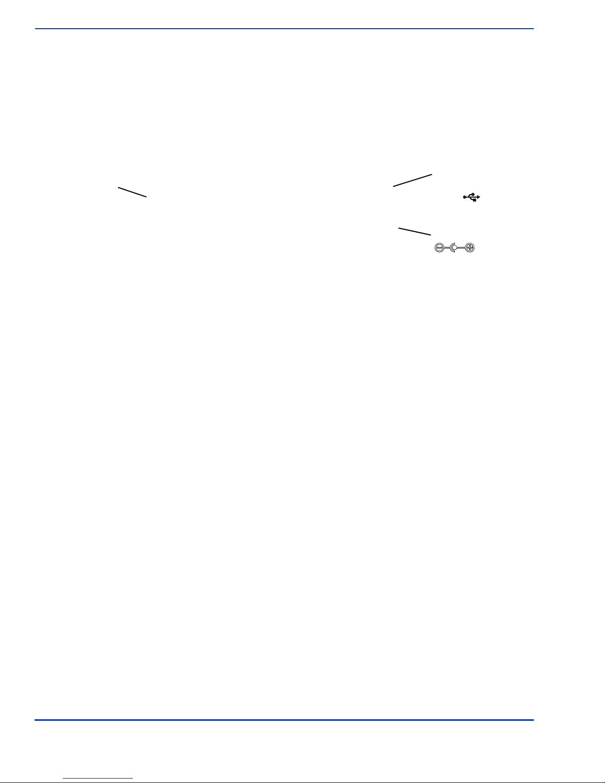
Connect Data and Power
RS232 and UBS
Power
Data Port
Ethernet
Data Port
There are connectors for Ethernet (optional), data, and power inside the connector cover. The
connections you need to make are dependant on your specific POS configuration and application
Installing the ViVOpay 8100e
RS232
To connect data and power
1. Connect your data cable to the RS232/USB or connect the Ethernet por t to a Ethernet
switch or hub.
2. Connect the power cable.
3. Pass the cables through the slots in the connector cover. Use the narrow slot for the power
cable to provide strain relief.
4. Replace the cover and secure it with the retaining screw.
5. Connect the power supply to a 110-220 VAC outlet.
ViVOpay 8100e User Guide 7
Page 12
Installing the ViVOpay 8100e
The ViVOpay 8100e displays the opening set of screens before it displays the
opening screens include:
• Copyright screen
• Firmware version screen
The reader should then display
Welcome
upon the POS application.
If the reader fails to power up, try reseating the power connector (or change to a different power
outlet). For more troubleshooting information, see “Troubleshooting” on page 11.
Mount the ViVOpay 8100e to a Surface
The ViVOpay 8100e can be mounted to a surface to prevent it from being accidently dislodged or
repositioned.
To mount the ViVOpay 8100e
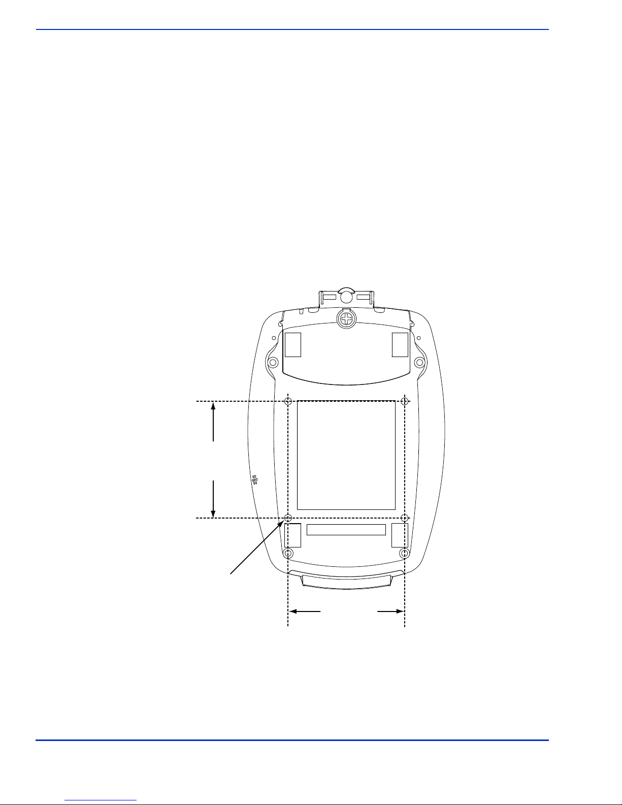
1. Drill four 3.5mm (9/64 inch) holes in the surface where the ViVOpay 8600 will be mounted.
Use the hole spacing shown in Figure 1.
or
Please present card
Welcome
screen. The
or similar wording, depending
76.20 mm
3.0 inches
Mounting Holes x4
76.20 mm
3.0 inches
Figure 1. Mounting hole locations
2. Position the ViVOpay 8100e over the mounting holes and use four M3 screws (not
supplied) long enough to secure the ViVOpay 8100e to the mounting surface.
ViVOpay 8100e User Guide 8
Page 13

Mounting the Wedge Bracket
The optional wedge bracket tilts the ViVOpay another 7° for easier viewing. The wedge bracket is
fastened to the ViVOpay 8100e using the four mounting holes.
To mount the wedge bracket
1. Align the mounting bracket over the mounting holes with the thickest end over the
connector cover.
2. Fasten in place with four M3 screws as shown in Figure 2.
Installing the ViVOpay 8100e
Figure 2. Attaching the wedge bracket
ViVOpay 8100e User Guide 9
Page 14

Testing the Installation
After you have completed the installation and have checked for PCI conformance, check that the
ViVOpay 8100e and the POS are communicating correctly by performing a sample transaction using
a contactless card and a magstripe card.
You can also test basic functionality using the Onboard Diagnostics (OBD) described in “Onboard
Diagnostics” on page 12.
Installing the ViVOpay 8100e
ViVOpay 8100e User Guide 10
Page 15

Troubleshooting and Maintenance
Troubleshooting
The ViVOpay 8100e readers are reliable and easy to troubleshoot. The components that may require
troubleshooting include the power supply, the reader, and the data cable.
Symptom Possible Cause Remedy
General Issues
Reader does not appear to be
powered on—no LEDs lit, no
LCD display.
Reading Cards/Fobs/Phones
• Reader not powered on.
• Incorrect power supply used.
• Check cable connections.
• Verify that power is on and correct voltage and
current are present.
• Replace the power supply.
• Verify that power cable plug is fully inserted.
• Replace the reader.
Chapter 3
LEDs do not light and beeper is
not audible when
card/fob/phone is presented.
Some cards/fobs/phones read,
but not all.
Communication to POS/ECR
No data is received, or data is
garbled.
• Card/fob/phone not properly
presented.
• Metal or RF interference.
• Firmware issue (contact your local
support representative).
• Reader not powered on or incorrect
voltage.
• Incorrect power supply used.
• Unsupported card/fob/phone used.
• Wrong firmware (contact your local
support representative).
• Possible bad card/fob/phone.
• Unsupported card used.
• Faulty or incorrect cable connections.
• Unsupported card used.
• Contactless application is not
installed on terminal (for serial
connections only).
• Magstripe card not swiped correctly.
• Magstripe card not level during card
swipe.
• The POS application is not using the
correct communications parameters.
• Present card/fob/phone closer to the reader
and ensure it’s parallel to the reader’s display.
• Verify that the card/fob/phone is valid/current.
• Test with “ViVOcard Contactless Tes t Card”
part number 241-0015-03.
• Try a different card/fob/phone.
• Verify that the unit is not near any large metal
objects.
• Verify that correct firmware is loaded (local
support representative only).
• Verify that power is on and correct voltage and
current are present.
• Verify that power cable plug is fully inserted.
• Replace the reader.
• Verify that correct firmware is loaded on
reader (local support representative only).
• Check to see if card/fob/phone is damaged.
• Try a different card/fob/phone.
• Check that the cable connection is secure and
in the correct port on the POS/ECR.
• Check that the POS/ECR has the correct
software application to accept data from the
contactless reader (may need assistance from
the POS vendor).
• Try a different card/fob/phone or magstripe
card if testing the magstripe reader.
• If testing with the magstripe card, try turning
the card around; make sure that the card is
level during the card swipe.
• Contact the payment processor for an
application upgrade.
• Check that the cable is correctly attached to
the back of the ViVOpay 8100e
• Check the POS application.
ViVOpay 8100e User Guide 11
Page 16
Onboard Diagnostics
The ViVOpay 8100e has a built-in diagnostics program accessible through the RS232 interface. If
you did not purchase an RS232 data cable with your ViVOpay 8100e, you will need one to access
the diagnostic tests. The Onboard Diagnostics (OBD) tests the following components of the ViVOpay
8100e.
Test Possible Results
LCD Test Pass/Fail
Touch Screen Test Pass/Fail. This test is not valid for the ViVOpay 8100e.
Key Test Pass/Fail 1234567890<cancel><clear><enter>
LED Test Pass/Fail
Buzzer Test Pass/Fail
Magstripe Test Pass Tracks 1 or 2 or 3/Fail
RFID Test Pass Type A or B/Fail
Security Keys Test KPK, DUKPT, Master 1234567890
Accessing the OBD Tests
Troubleshooting and Maintenance
To connect the ViVOpay 8100e to a terminal emulator
1. Connected the RS232 data cable to the ViVOpay 8100e as described in “Connect Data
and Power” on page 7.
2. Launch the terminal emulation program and set the serial communication parameter of
the terminal emulation program to the following:
Baud rate: 115200
Parity: none
Data bit: 8
Stop bit: 1
Flow control: none
3. Connect the BD-9 end of the data cable to the COM port of a computer running a terminal
emulation program.
To enter the Onboard Diagnostics
1. Power off the ViVOpay 8100e by removing the power supply from the power receptacle.
2. Plug the power supply back into the power receptacle.
ViVOpay 8100e User Guide 12
Page 17
Troubleshooting and Maintenance
Main Menu
1 Onboard Diagnostics
2 Setup
3 Test Applications
4 Version Information
5 Boot
X Exit
ViVOpay AR Diagnostics
1 Test All
2 LCD
3 Touch Screen
4 Keypad
5 LEDs
6 Tone
7 Magstripe
8 RFID and Antenna
9 Security Elements
0 Test Results Summary
|: Next Page, X Exit
Test Results
LCD Pass
Touch Screen Pass
Keypad Pass
LED Pass
Buzzer Test Pass
Magstripe Card T1 T2 T3
RFID Type B card
Security
KPT exists
DUKPT exists
Master session slots occupied
- - - - - 6 - - - Press any key to return to main
3. Press the 3 key and hold it down until the Main Menu screen appears. This is
approximately 40 seconds after power is first applied.
4. Press the 1 key to enter the OBD. The ViVOpay AR Diagnostics menu displays.
The
ViVOpay AR Diagnostics
Test Results Summary
The
T est Results Summary
returned to normal mode, all results are cleared. If you reenter the
are marked as not performed.
1. Press 0 on the ViVOp ay AR Diagnostics screen . The Test Results screen is displayed
with the results of all the tests run.
ViVOpay 8100e User Guide 13
screen is the main menu.
displays the results of all tests performed. Once the ViVOpay 8100e is
ViVOpay AR Diagnostics
, all test
Page 18

Test All
AR
LCD Test
1 Test Character Display (not run)
2 Test all pixels OFF (not run)
3 Test clarity of display (not run)
CANCEL(X) Exit to main menu
Select Test with 1, 2, or 3 and:
Press ENTER (O) to pass test
Press CANCEL (X) to fail test
4 Set 8100 Contrast (not run)
LCD Test
Troubleshooting and Maintenance
Test All runs the entire test sequence and displays the results.
1. Press 1 when the ViVOpay AR Diagnostics screen is displayed. All of the tests are run
in sequence and the results are displayed. See each individual test for information.
The LCD test turns the pixels on/off and checks screen clarity to verify that the LCD screen is working
properly. The results will be displayed on the LCD.
1. Press 2 from the ViVOpay AR Diagnostics screen. The AR LCD Test screen is
displayed.
2. Press 1. The display will fill with alpha characters on line one and numeric characters on
line 2.
3. Press ENTER if the correct screen is displayed otherwise press CANCEL to fail the test.
The AR LCD Test screen is displayed.
4. Press 2. All pixels should be turned off and the screen should be bright.
5. Press ENTER if the correct screen is displayed otherwise press CANCEL to fail the test.
The AR LCD Test screen is displayed.
6. Press 3. Both lines of the display are filled with the # character.
7. Press ENTER if the correct screen is displayed otherwise press CANCEL to fail the test.
The AR LCD Test screen is displayed.
8. Press 4. Y ou can change the contrast by pressing the 7 key for more contrast or the 9 key
for less contrast. A numeric value (20 high to 42 low) for the contrast is displayed.
9. To save an new contrast se tting, press ENTER and press the keys as instructed b y the
prompt.
10. Press CANCEL to exit back to the main menu.
Touch Screen Test
The Touch Screen test does not apply to the ViVOpay 8100e.
CANCEL
to abort this test.
Keypad Test
This test asks you to enter each of the keys in sequence to verify that the keypad is working correctly .
The results will be displayed on the LCD.
Test All
skips this test or press
ViVOpay 8100e User Guide 14
Page 19
LED Test
Keypad Test
Press key 1
LED Test
Press Enter if all 4 LEDs are
turned On and OFF, press X
if not
Tone Test
Press Enter if you hear tones
ramp up then down, press X if
not
Troubleshooting and Maintenance
1. Press 4 on the ViVOp ay AR Diagnostics screen. The Keypad Test screen is displayed.
2. Press key 1. The screen then asks for the next key in sequence.
3. Continue pressing each key as requested.
When you have finished testing the keys, the keypad will be tested for intrusion. Remove
your hand and any other object from the keypad until the test is complete.
Note: If the tamper value is too high (failed), the ViVOpay 8100e will not accept PIN entry. To
see if the keypad passed the tamper test, use the Test Results Summary option. Readers
that fail the keypad tamper test should be returned for recalibration.
Tone Test
This test asks you to verify that all of the LEDs are working correctly. The results will be displayed
on the LCD.
1. Press 5 on the ViVOpay AR Diagnostics screen. The LED Test screen is displayed.
2. Press ENTER if all four LEDs flash on and off in sequence otherwise, press CANCEL to
indicate that the LEDs did not flash. The ViVOpay AR Diagnostics screen appears.
This test asks you to verify that the buzzer is audible. The results will be displayed on the LCD.
1. Press 6 on the ViVOpay AR Diagnostics screen. The Tone Test screen is displayed.
ViVOpay 8100e User Guide 15
Page 20

2. Listen for the tones and make sure they ramp up and then down.
Magstripe Test
Swipe any Magstripe
card
RFID Test
Present RFID card
3. Press ENTER if you hear the tones otherwise press CANCEL to indicate that the tones
did not ramp up and down.
Magstripe Test
This test asks you to swipe a magstripe card through the slot at the top of the ViVOpay 8100e and
displays the tracks read correctly. The results will be displayed on the LCD.
1. Press 7 on the ViVOpay AR Diagnostics screen. The Magstripe Test screen is
displayed.
Troubleshooting and Maintenance
1. Swipe a card with a magnetic stripe through the slot on the top of the ViVOpay 8100e.
2. The panel displays the results of the swipe; either the card has been successfully read or
an error is indicated.
3. Press any key to return to the ViVOpay AR Diagnostics screen.
RFID and Antenna Test
This test asks you to present a contactless card/phone/fob close to the touch screen to verify that
the antenna is able to detect a contactless card. The results will be displayed on the LCD.
1. Press 8 on the ViVOpay AR Diagnostics screen. The RFID Test screen is displayed.
2. Present
is parallel to the touch screen.
3. Press any key to return to the ViVOpay AR Diagnostics main menu.
the card/fob/phone in close proximity to the reader and so that maximum surface area
The screen indicates if a card/phone/fob has been detected.
Security Elements Test
This test verifies that the KPT and DUPKT keys are loaded into the ViVOpay 8100e. It also verifies
which slot contains the master Key. The results will be displayed on the LCD.
ViVOpay 8100e User Guide 16
Page 21
1. Press 9 on the ViVOpay AR Diagnostics screen. The Security Elements Test screen
Security Elements
KPK Exists
DUPKT exists
Master session slots occupied
Press any key to continue
ViVOpay AR Diagnostics
0 ICC
1 SAMs
2 SAM2 only
Press any key to continue
is displayed.
2. Press any key to return to the ViVOpay AR Diagnostics main menu.
Contact Interface Tests
1.
To test the SAM slots, press
ENTER
Troubleshooting and Maintenance
from the Onboard Diagnostics Main Menu.
If the ViVOpay 8100e does not have an ICC contact card slot, skip the first test.
2. Press 0 to check the contact card reader.
3. Press 1 to check a SAM in SAM slot 1.
4. Press 2 to check a SAM in SAM slot 2.
Maintenance
The ViVOpay 8100e contains no user-serviceable parts within its enclosure. Do not open the
ViVOpay 8100e enclosure.
WARNING:Attempting to open the ViVOpay 8100e enclosure will trigger security measures
and it will stop functioning even after reassembly!
You can upgrade the ViVOpay 8100e
Upgrading the Firmware
Y ou can upgrade the firmware of the ViVOp ay 8100e
the following from your
• New ViVOpay firmware
• ViVOpay download utility
• USB data cable
’s firmware if required.
ViVOpay 8100e
if required for your application. Y ou will need
distributor:
ViVOpay 8100e User Guide 17
Page 22

Troubleshooting and Maintenance
You also need a PC with a USB port. The PC should have the required USB driver USBSER.SYS
and HID.DLL files. If not, they are available for download from Microsoft’s website.
To upgrade the firmware
1. Make sure you have the
USBSER.SYS and HID.DLL files
installed on the PC.
2. Copy the firmware image and ViVO download utility, provided by ViVOtech Support or
your ViVOtech representative, to the PC you are using for the upgrade.
3. Copy the vivopay.inf file to the Windows\inf directory.
4. Connect the USB data cable to the ViVOpay 8100e and PC (see “Connect Data and
Power” on page 7).
5. Double click the ViVO download utility icon or .exe to start the utility.
6. Power on the ViVOpay 8100e. The bootloader version appears under the ViVOtech logo.
7. Click Download Image.
8. When prompted, locate and select the firmware (.hex file) to download and click OK.
A progress bar indicates the status of the download. It will take approximately eight
minutes to complete the download.
9. When the download is complete disconnect the ViVOpay 8100e from the PC and power.
The new firmware will be active next time you apply power to the ViVOpay 8100e.
10. Connect the ViVOpay 8100e to the POS with the appropriate data cable.
11. Reconnect power.
ViVOpay 8100e User Guide 18
Page 23
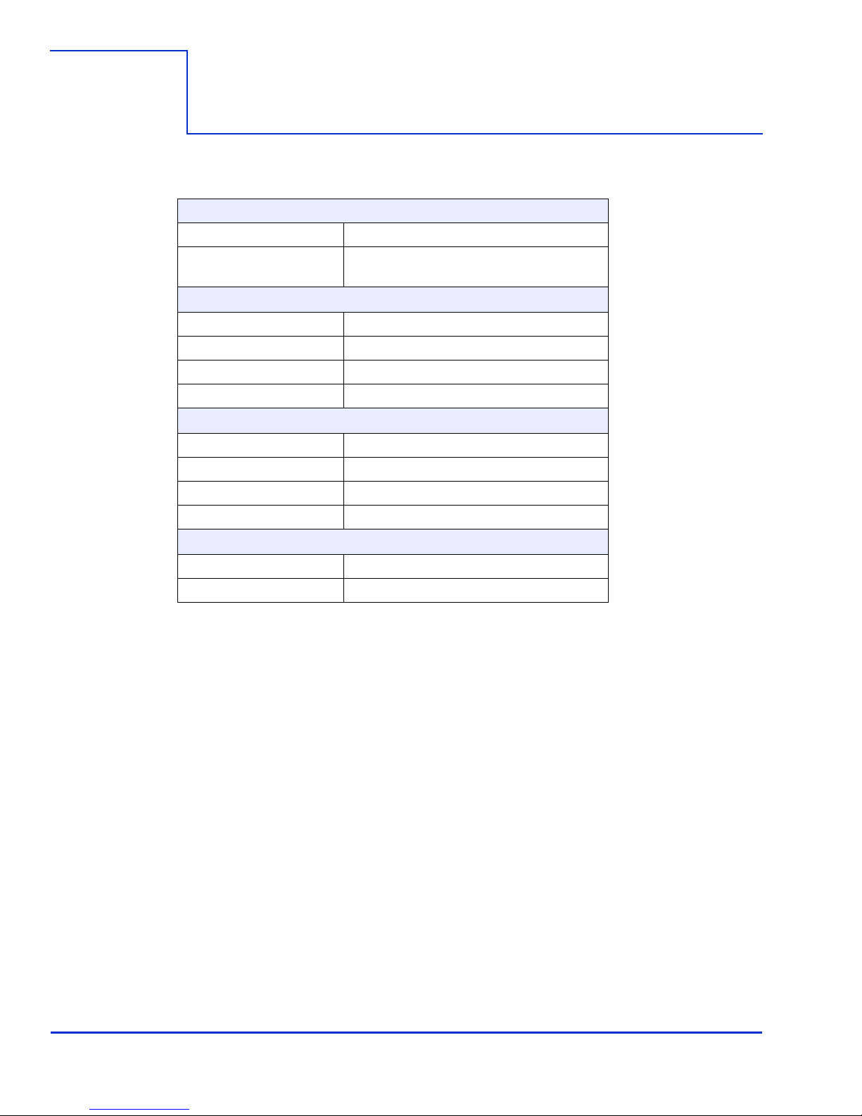
ViVOpay 8100e Specifications
RF Interface
Frequency 13.56 MHz
Standards ISO 14443 Type A/B
ISO 18092
Physical
Length 190.5 mm (7.5 in)
Width 129.45 mm (5.1 in) maximum
Depth 47.63 mm (1.875 in)
Weight 0.4 Kg (0.9 lbs)
Environmental
Operating Temp. 0 to 40° C (32 to 104° F)
Storage Temp. -20 to 60° C (-4 to 140° F)
Appendix A
Specifications
Operating Humidity 0 to 85% non-condensing
Operating Environment Indoor only
Power
Voltage 9-12 Vdc regulated, +/- 10%
Consumption 5 W maximum
ViVOpay 8100e User Guide 19
Page 24

Regulatory Compliance
FCC Part 15 Class B Equipment
This equipment has been tested and found to comply with the limits for a Class B digital device,
pursuant to Part 15 of the FCC Rules. These limits are designed to provide reasonable protection
against harmful interference in a residential installation. This equipment generates, uses and can
radiate radio frequency energy and, if not installed and used in accordance with the instructions, may
cause harmful interference to radio communications. However, there is no guarantee that
interference will not occur in a particular installation. If this equipment does cause harmful
interference to radio or television reception, which can be determined by turning the equipment off
and on, the user is encouraged to try to correct the interference by one or more of the following
measures:
• Reorient or relocate the receiving antenna.
• Increase the separation between the equipment and receiver.
• Connect the equipment into an outlet on a circuit different from that to which the receiver is
connected.
• Consult the dealer or an experienced radio/TV technician for help.
FCC Information for User
Specifications
The users manual or instruction manual for an intentional or unintentional radiator shall caution the
user that changes or modifications not expressly approved by the party responsible for compliance
could void the user's authority to operate the equipment. In cases where the manual is provided only
in a form other than paper , such as on a computer disk or over the Internet, the information required
by this section may be included in the manual in that alternative form, provided the user can
reasonably be expected to have the capability to access information in that form.
Industry Canada Class B Equipment
This Class B digital apparatus complies with Canadian ICES-003.
Cet appareil numérique de la classe B est conforme à la norme NMB-003 du Canada.
Industry Canada Information for User
Operation is subject to the following two conditions: (1) This device may not cause harmful
interference, and (2) this device must accept any interference, including interference that may cause
undesired operation of the device.
Cet appareil numérique de la classe B est conforme aux normes NMB-003, CNR-Gen, et CNR-210
du Canada. Son fonctionnement est assujetti aux deux conditions suivantes: (1) Cet appareil ne peut
pas provoquer d’interférences nuisibles et (2) cet appareil doit accepter toute interférence reçue, y
compris les interférences pouvant entraîner un fonctionnement non désiré.
ViVOpay 8100e User Guide 20
Page 25

Discover Zip
Discover's contactless payment product that utilizes contactless technology.
Electronic Cash Register (ECR)
The combination of a traditional cash register and a POS terminal, often PC-based.
ExpressPay from American Express
American Express contactless payment product that utilizes contactless technology.
Firmware
Software that is embedded in a hardware device that allows reading and executing the
software, but does not allow modification, e.g., writing or deleting data by an end user.
Example: Firmware is a computer program in a read-only memory (ROM) integrated circuit
chip. A hardware configuration is usually used to represent the software.
Example: Firmware is a program embedded in an erasable programmable read-only memory
(EPROM) chip, which program may be modified by special external hardware, but not by an
application program.
Fob
A key chain device or other non-standard credit card sized form factor that has an embedded
radio frequency (RF) chip.
Glossary
MasterCard PayPass
MasterCard's contactless payment product that utilizes contactless technology.
NFC
Near Field Communications.
NFC Phone
Near Field Communications (NFC) phone. A technology that enables comm unication between a
secure element in a mobile device and a contactless reader to make credit/debit payments.
Also see UICC.
PCI 2.1
The Payment Card Industry Security Standards Council (PCI SSC) mission is to enhance
payment account data security. PCI 2.1 is a set of standards created by PCI SSC to increase
the security of card data.
Point of Sale (POS)
Refers to terminals used in retail stores with a magnetic stripe reader, keyboard, display and
autodialer modem or IP connection, connected to the telephone/internet network and used for
on-line credit/debit authorization. Can also be connected to a host computer, which handles all
transaction processing including item price look-up , data collection, and credit/debit
authorization.
Proximity Payments
Payment method utilizing contactless technology such as RF, Infrared (IrDA) or Near Field
Communications (NFC).
Radio Frequency (RF)
Any frequency that corresponds to radio signals, including those used by cellular telepho nes
and wireless networks.
RF Reader
The Point of Sale device that receives the RF transmission from a card, fob or NFC phone.
Visa payWave
Visa's contactless payment product that utilizes contactless technology.
ViVOpay 8100e User Guide 21
 Loading...