


VivoResponder™
Release VMLA-177-00 Rev. 1
VivoResponder™
1

The VivoResponder™
The VivoResponder™
e VivoResponder™ with LifeShirt® technology is a lightweight chest strap with embedded sensors
that monitors breath rate, heart rate, activity, posture, and skin temperature. is system is designed to
help rst responders improve performance by increasing awareness of physiologic intensity, recovery,
and tness, and understanding of the relationship between strenuous activity and physiology.
Real-time life-sign information is transmitted from the VivoResponder™ to a remote location where
VivoCommand soware, running on a PC, displays real-time vital signs of each team member’s physiological data and can be saved for analysis.
is system manual shows the simple steps to set-up, use and maintain the VivoResponder™ vital sign
monitoring system.
CAUTION: If user has a pacemaker, it is necessary to consult with his/her physician and/or the
pacemaker manufacturer prior to use of the VivoResponder™ to ensure that it will not interfere
with the proper functioning of the pacemaker.
CAUTION: If user has a pacemaker, pacemaker pulses will count as heartbeats.
NOTE: e VivoResponder™ is not for use in medical applications. Before starting any strenuous exercise,
user should always consult his/her physician.
Release VMLA-177-00 Rev. 1
VivoResponder™
17

Table of Contents
e VivoResponder™ Kit .................................................................... 19
How to Put On the VivoResponder™ .................................................20
Shoulder Strap .....................................................................20
ECG Patches .........................................................................20
Chest Strap ...........................................................................20
Sensor Module .....................................................................21
Ending a Monitoring Session ............................................................ 22
Care and Maintenance ........................................................................23
Recharging the Battery ......................................................23
Cleaning the System ...........................................................23
Drying the Strap ..................................................................24
Cleaning the Sensor Module .............................................24
Re-installing Polar Wearlink ............................................24
Storing and Shipping ......................................................... 24
Appendix A: Sizing the Chest and Shoulder Straps .....................25
Appendix B: Connecting to a Data Logger ..................................... 26
Cautions ............................................................................................... 27
Service ............................................................................................... 27
Specications ........................................................................................ 28
Release VMLA-177-00 Rev. 1
VivoResponder™
1

The VivoResponder™ Kit
VivoResponder™ Attaché
Case
VivoResponder™ Base
Station
USB RX
with USB Cable
Holster with Belt Clip
VivoResponder™
Shoulder Strap
VivoResponder™ Chest
Strap
VivoResponder™ Sensor
Module RX
(Shipped INSIDE the Holster)
Battery Charger
Wash Bag
Polar Wearlink
(removable)
Factory-installed
in the Chest Strap
Release VMLA-177-00 Rev. 1
CD and Set-Up Guide
VivoResponder™
1
D
C
B
O
N
M
J
I
H
G
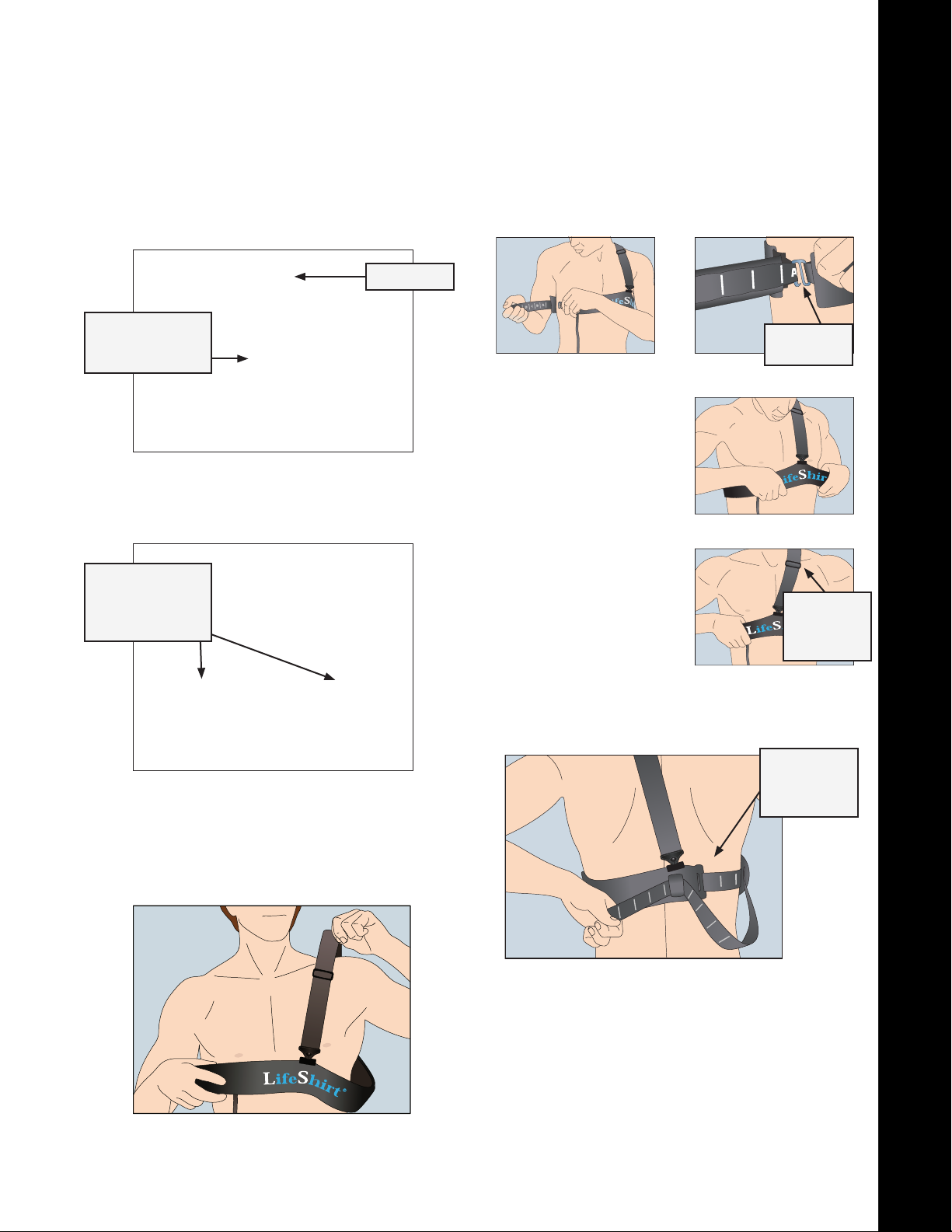
Put on the VivoResponder™
Attach the Shoulder Strap
1.
Snap the Shoulder Strap onto the front and back of the Chest
Strap. e metal slider should be closer to the front.
Metal Slider
b. Hold the letter end of the Chest Strap and slip the hook
through the loop that ts. Chest Strap should be snug, but
not too tight. Each letter corresponds to a loop.
Shoulder Strap
attached to
Chest Strap.
Moisten the ECG Patches
2.
Moisten your nger with water and wet each of the three
raised patches of silver fabric on the back side of the Chest
Strap.
ECG Patches
should be damp
not drenched
(2 patches pictured)
Put on the VivoResponder™
3.
a. Slip the Shoulder Strap over one shoulder—
NOT OVER YOUR HEAD.
Slip Hook
Into Loop
c. Move the VivoResponder™
Chest Strap until the “S”
in “LifeShirt” on the Chest
Strap is centered on your
sternum.
d. If needed, adjust the
Shoulder Strap with the
slider to hold the Chest
Strap in place.
Adjust the
Shoulder
Strap with
the Slider
e. e Chest Strap is extra long to accommodate users of
various sizes. If there is excess, thread it through the loop
on the back.
Slide excess
strap through
the loop in
the back
Slip arm through Shoulder Strap
NOTE: If you are unsure about t, see Appendix A.
Release VMLA-177-00 Rev. 1
VivoResponder™
20
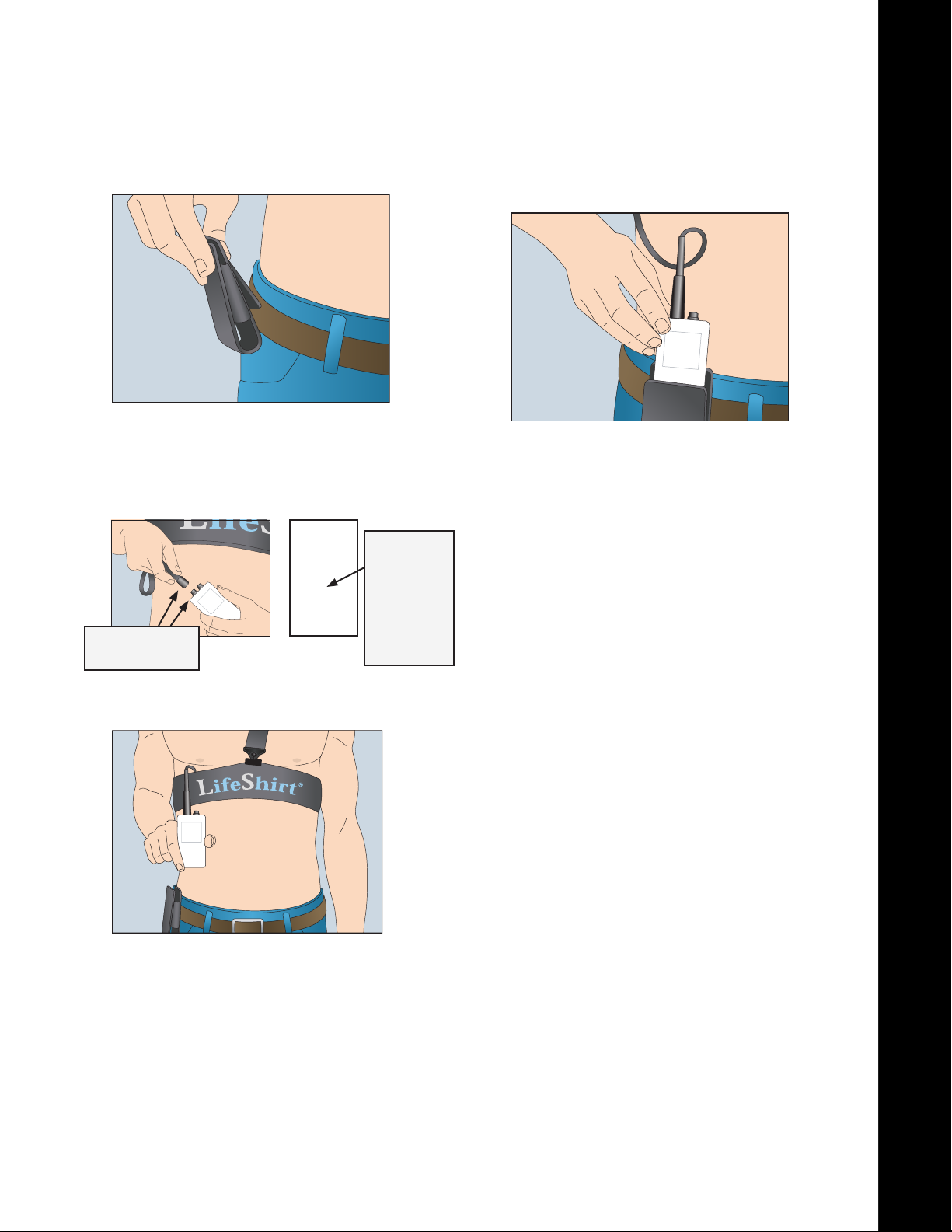
Put on the VivoResponder™
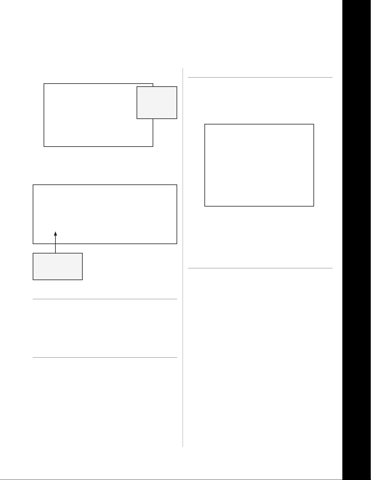
Attach the Holster to your belt
4.
Plug in the Sensor Module
5.
a. Line up the white arrows on the strap cable connector and
the Sensor Module; snap together. When connected, the
LED ashes green on the back of the Sensor Module.
c. Slide Sensor Module into the Holster in the same upright
position.
d. e VivoResponder™ is now calibrated to your body posi-
tion and is operational. ere is no other “On Switch.”
Line up the
WHITE ARROWS
b. Stand upright and hold the Sensor Module upright
for 10 seconds.
green when
connected
Light on
Back of
Sensor
Module
ashes
Operation Complete
You are now ready to start collecting life-sign data.
C
Release VMLA-177-00 Rev. 1
VivoResponder™
21
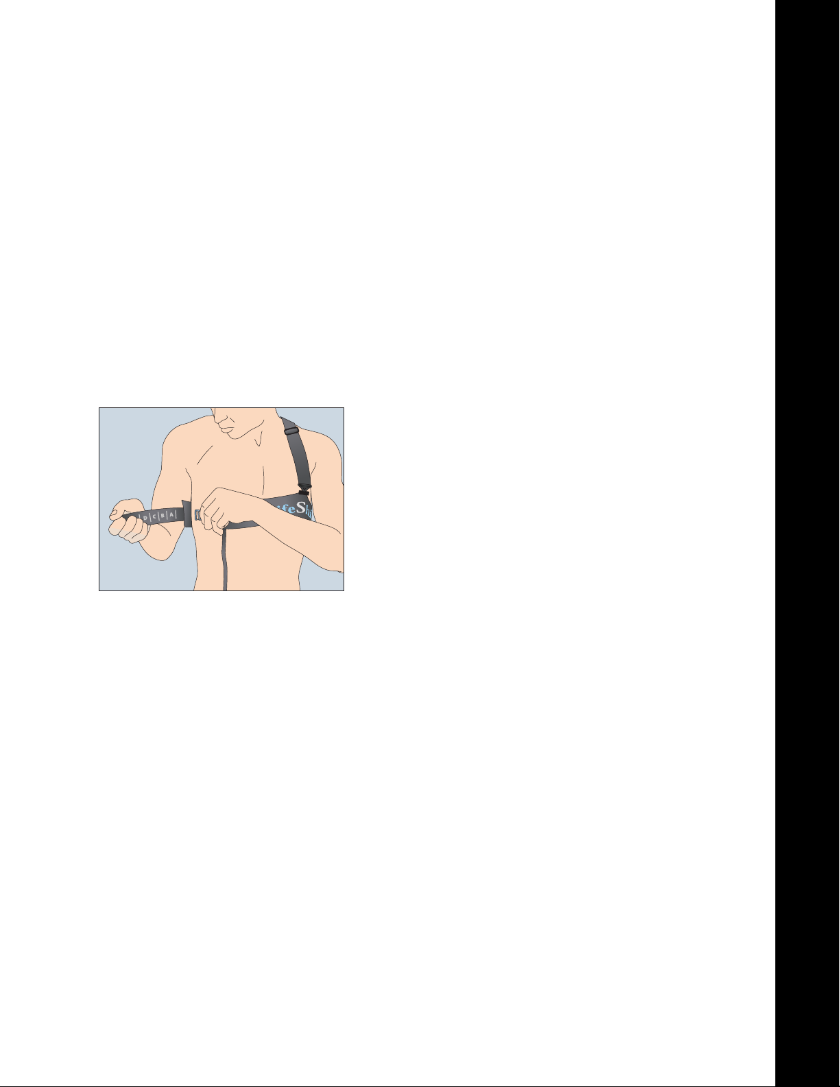
Ending a Monitoring Session
Disconnect the External Radio by gently sliding the
1.
locking ring back.
Disconnect the Sensor Module by gently sliding the
2.
locking ring back.
Unsnap the shoulder strap by tilting the suspender hook in
3.
the center of your chest.
Using two hands pull the VivoResponder™ Chest Strap
4.
slightly away from your body until the dampened
ECG pads are no longer in contact with your skin.
Rotate the strap around your body so that the hook
5.
sits in front of your chest.
Slide the hook out of its loop and remove the strap.
6.
Replace all the VivoResponder™ components in the
7.
Attaché Case for storage or return.
Operation Complete
C
Release VMLA-177-00 Rev. 1
VivoResponder™
22
Care and Maintenance
Recharging the Battery
Connect the Battery Charger to a 120V AC power outlet and
1.
plug the connector into the Sensor Module.
Line up the white arrows on the connector and the Sensor
2.
Module and gently push. You will hear a “click” when it is
connected correctly and the charge indicator LED will illuminate yellow.
NOTE: You cannot charge when the Chest Strap is
connected. e charger and the Chest Strap use
the same connector on the Sensor Module.
Gently slide back
LOCKING RING
to remove.
Cleaning the System
e VivoResponder™ Chest Strap may be laundered in a
1.
washing machine:
• Gentle cycle
• Cold Water
• Standard detergent
IMPORTANT:
Always use the wash bag when laundering
DO NOT USE BLEACH
DO NOT DRY CLEAN
HANG DRY ONLY
Disconnect and store the Sensor Module.
2.
Detach the Shoulder Strap
3.
When charge is complete, the le LED will turn Green.
3.
Yellow Light:
Charging
Remove the connector by gently liing the Locking Ring at
4.
the base and sliding the connector away.
NOTE: e system should come fully charged. It takes
4 hours for a complete charge when totally empty.
A full charge will last approximately 220 hours
when plugged into an external radio or data
logger or approximately 48 hours with an
internal radio.
Green Light:
Charging
Complete
Twist the snap outward from chest to unfasten.
Unsnap and remove the Polar Wearlink from under the
4.
elastic, one snap at a time (there are two snaps).
Unsnap the Polar Wearlink and
remove prior to washing.
Polar Wearlink:
Front (top) and Back (bottom)
Plug the end of the connector with the wash cap.
5.
Release VMLA-177-00 Rev. 1
VivoResponder™
2
Care and Maintenance
read the cable through the Wearlink elastic, twice, to hold
5.
it in place during the wash.
Cap connector
and thread
cable through
Wearlink
elastic
Chest Strap ready to be placed in the wash bag.
Place the Chest Strap at into the wash bag and zip it up.
7.
Re-install the Polar Wearlink
On the outside of the VivoResponder™ strap (to the le of the
1.
printed word—LifeShirt) nd the elastic band with two (2)
female snaps underneath.
Slide the Wearlink under the elastic so that the word—
2.
Polar—is facing the same direction as the word—LifeShirt.
NOTE:
Remove
Polar Wearlink
before washing
Drying the Strap
Hang dry only. Do not dry the Chest Strap in machine or
1.
with hot air.
IMPORTANT:
DO NOT HEAT OR TUMBLE DRY THE STRAP
Cleaning the Sensor Module
Wipe the Sensor Module with a damp cloth.
1.
CAUTION: e VivoResponder™ Sensor Module is water
resistant, but it is not intended to be sumerged
in water. DO NOT SUBMERGE IN WATER.
Slide the Wearlink under the elastic, then snap in place.
Snap the Wearlink onto the band one snap at a time,
3.
listening for the snapping sound to verify it is properly attached.
Storing and Shipping
For best results, store and ship all VivoResponder™ components in
their original packaging.
CAUTION: Do not disassemble the Sensor Module;
this will void the warranty.
Release VMLA-177-00 Rev. 1
VivoResponder™
2
Appendix A: Sizing Chest & Shoulder Straps
Sizing the Chest Strap
e Chest Strap comes in three sizes:
1.
A. Standard: S thru 3XL (Provided in the kit.)
B. Petite: XS
(Must be ordered separately or replaces standard strap.)
C. Long Tail: Cable is extra long
(Must be ordered separately or replaces standard strap.)
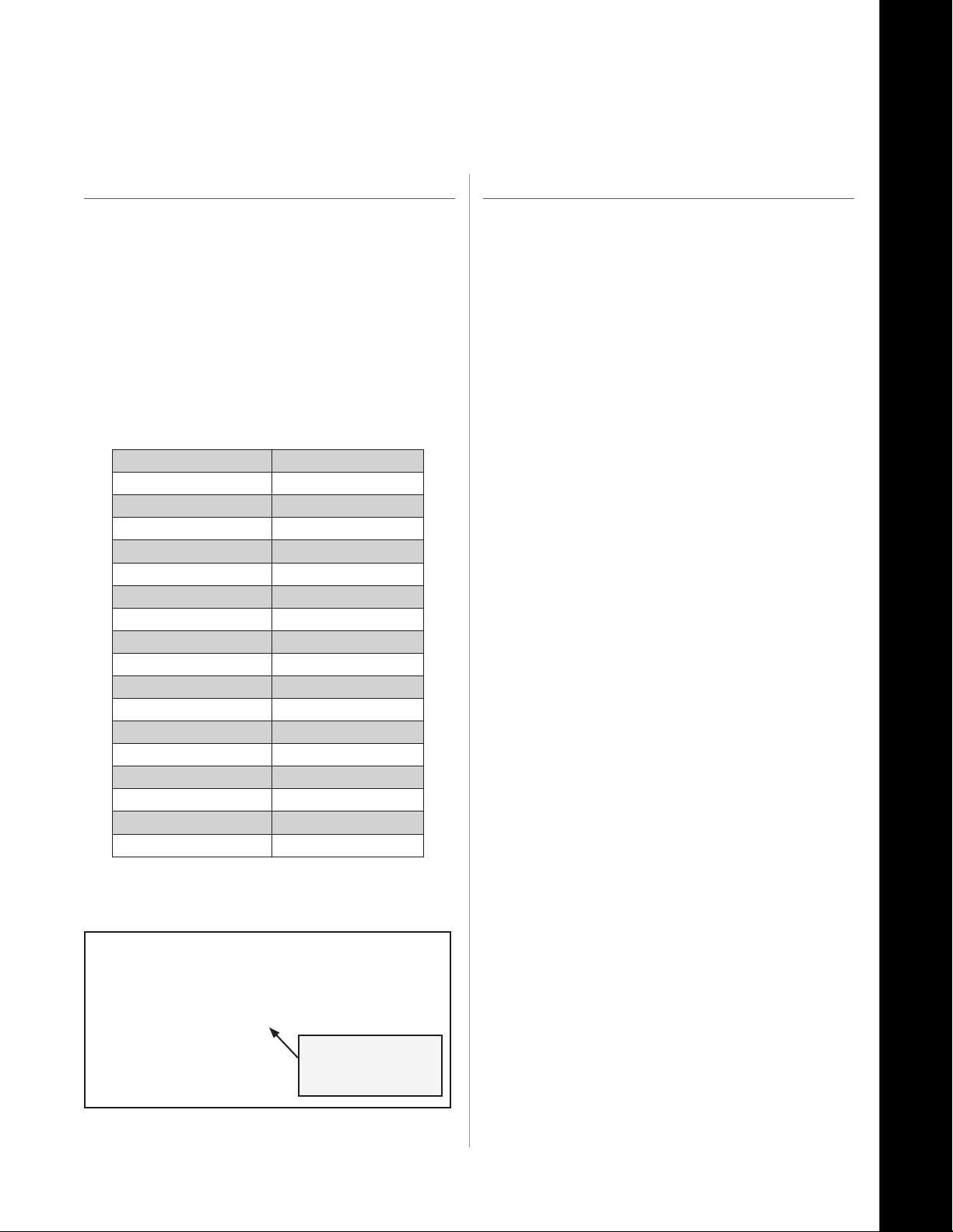
Use a tape measure to measure chest just below the sternum.
2.
Chest measurement determines which Hook Loop to use
3.
with the strap. Refer to the chart.
CHEST SIZE (inches) HOOK LOOP LETTER
32 or less Petite Strap
33-34 A
35-36 B
37-38 C
39-40 D
41-42 E
43-44 F
45-46 G
47-48 H
49-50 I
51-52 J
53-54 K
55-56 L
57-58 M
59-60 N
61-62 O
63-64 P
Sizing the Shoulder Strap
e Shoulder Strap is available in three dierent
1.
congurations:
A. Standard (Provided in the kit.)
B. XL
(Optional; swap the standard Shoulder Strap by contact-
ing VivoMetrics, Inc. Customer Service at 800-631-4445)
C. Velcro adjustment instead of slider.
(Available as an accessory by contacting VivoMetrics, Inc.
Customer Service at 800-631-4445)
Using the sizing chart above, nd the hook loop letter that
4.
corresponds to chest size. If you fall between sizes go to the
size below.
HOOK LOOP LETTERS
correspond to
CHEST SIZE
Release VMLA-177-00 Rev. 1
VivoResponder™
2
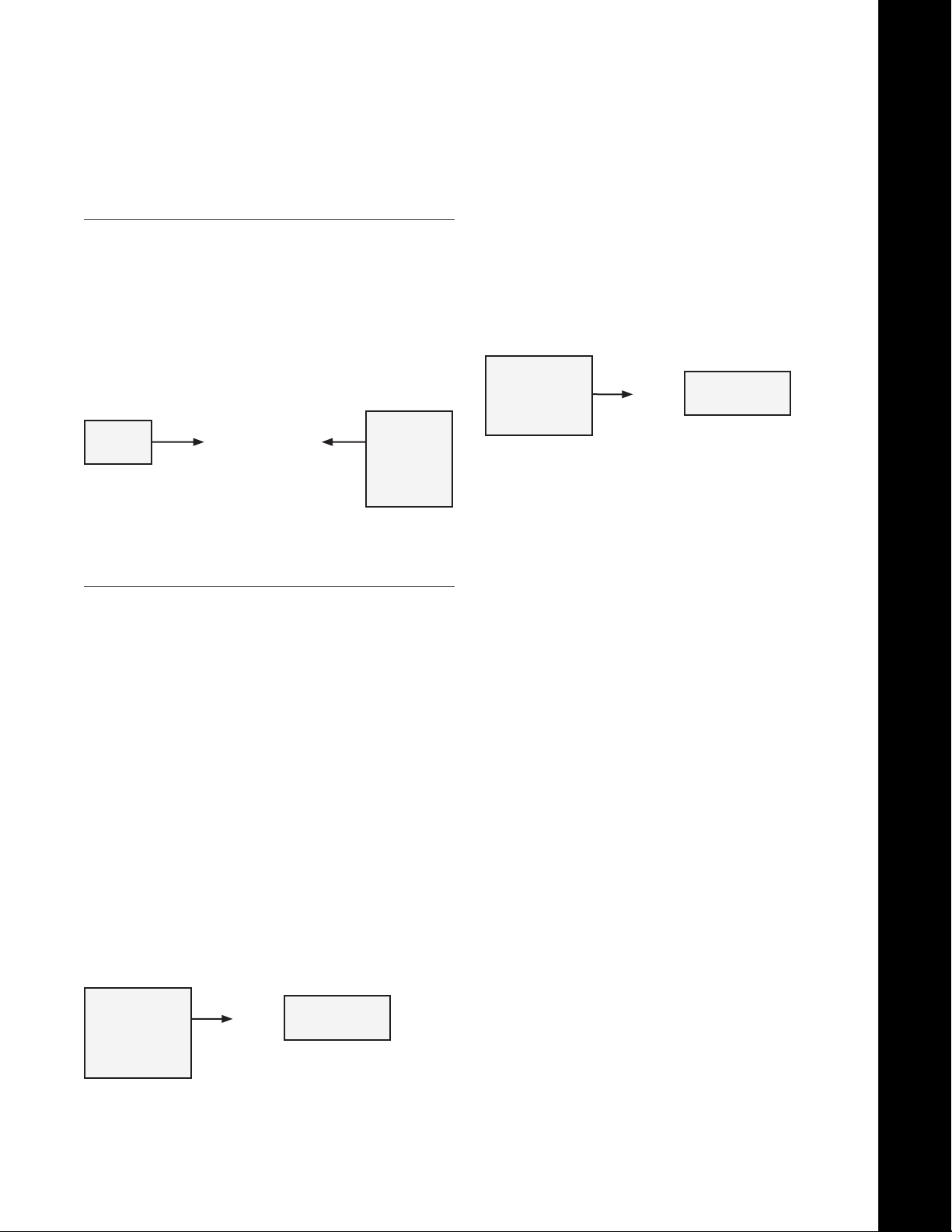
Appendix B: Connecting to a Data Logger
Data Logger
If you are using the VivoResponder™ with VivoResponder™ Sensor Module LVTTL and a Data Logger, refer to the Data Logger
manual.
Data
Logger
VivoRe-
sponder™
Sensor
Module
External Radio
If you are using an external radio follow the instructions below to
connect.
NOTE: If you are using an external radio, you either have a Sensor
Module RS232 or a Sensor Module LVTTL, depending on the external radio system you are plugging into.
Locate the second connector on the top of the Sensor Mod-
1.
ule.
Plug the supplied cable into the radio.
2.
Plug the other end of the cable into the VivoResponder™ Sen-
3.
sor Module.
VivoRe-
sponder™
Sensor Module
LVTTL
Turn on your external radio.
4.
Refer to the separate radio instruction manual for further
5.
information on your equipment.
Your Radio
Goes Here
VivoRe-
sponder™
Sensor Module
RS232
Your Radio
Goes Here
Release VMLA-177-00 Rev. 1
VivoResponder™
2

Cautions
Cautions
Read this manual before using the VivoResponder™
»
System.
If you have a Pacemaker, the Sensor Module will count
»
Pacemaker Pulses as heartbeats.
Consultation with your physician and/or the pacemaker
»
manufacturer prior to use ofVivometrics is necessary to
ensure that it will not interfere with the proper functioning of the pacemaker.
Always follow the recommended washing instructions
»
to clean the VivoResponder™ Chest Strap in the VivoResponder™ System Manual.
Do not use the VivoResponder™ System on an airplane.
»
is product has not been tested to FAA guidelines.
Do not engage in water sports, such as swimming, while
»
wearing the VivoResponder™ System. May cause electric
shock.
Do not use the VivoResponder™ System in extreme envi-
»
ronments (below -14°F, or above 158°F).
Use only approved chargers to charge the Sensor Module
»
battery.
Do not disassemble the Sensor Module.Do not heat the
»
Sensor Module over 163°F or incinerate it.
Remove the VivoResponder™ System before using a de-
»
brillator. May cause electric shock.
Arrange all power cords and cables so that they do not
»
constitute a hazard.
Customer Support
Limited 0-Day Warranty
VivoMetrics, Inc. warrants to the original consumer/purchaser
that this product will be free from defects in material or workmanship for 90 days from the date of purchase.
Warranty does not cover damages due to misuse, abuse,
»
accidents or negligence of the precautions; improper
maintenance, cracked or broken cases.
Warranty does not cover damage or consequential
»
damage caused by service not authorized by VivoMetrics, Inc.
During this warranty period (90 days), the product will be either repaired or replaced (at your distributor’s option) without
a charge.
VivoMetrics Customer Support
Telephone: 800-631-4445 (inside U.S.A.)
805-667-2225 (outside U.S.A.)
Fax: 805-667-6646
Email: help@vivometrics.com
Release VMLA-177-00 Rev. 1
VivoResponder™
27

Cautions and Specications
Specications
ENVIRONMENTAL LIMITS
Altitude: 26,000 .
Humidity: 100%
Temperature: -14°F to 150°F
Operating Temperature: 85C
Measurement Temperature: 0C to 90C 0.3 C accuracy
Storage: 85C to 100C
Distance to base: maximum 20 meters
ViviResponder™ and transmitter can be immersed up to 1 meter of water.
Do not immerse for more then 30 mins
BATTERY
Power Req. (Battery Charger): 120V, 60Hz, 15W
Battery Capacity: Lithium-ion, 1950mAh
Battery Voltage: 3.7V nominal, (Li-Ion Curve)
CHEST STRAP
Fabric Composition: 84% nylon, 16% spandex
Strap Weight (without Wearlink): 6.6 oz. (187grams)
Strap Weight (with Wearlink): 7.5 oz. (212 grams)
Strap Dimensions: 53”x 2.75”x 0.25”
Fits sizes: Small to 3XL
Washing Temperature: Cold
Drying: Hang Dry
SENSOR MODULE
Dimensions: 3.75” x 1.75” x 0.74”
Weight: 4oz.
Connector type and model: Hirose
Housing: ABS Plastic, injection molded
POLAR WEARLINK HEART RATE RECEIVER, LD
Wearlink coded data bursts are inductively captured by the URB 2.1. Burst
timing is measured using 1mSec resolution. Integer valued heart beat in
BPM is produced from a running average of eight beats. If no beat is observed in 8 seconds, the averaged value is forced to zero and the OK bit
is set to false. e valid output data range is 1-255 with an upper value
(default=255) max safe HR value.
Respiration: 3 to 75 valid breaths per minute
Position: +/- 2 g vertical
+/- 2 g horizontal (side-side)
+/- 2 g horizontal (front-back)
ACCURACY
Respiration: +/- 5% of rate or 2 breaths
per minute,
whichever is greater.
Heart Rate: +/- 10% or +/- 5% BPM
Position: 8 bits
Activity: 8 bits
FILTERS
Heart Rate: 8 beat rolling avg. R-R inst. time
Respiratory Rate: 60 second rolling average
SKIN TEMPERATURE SENSOR, LD
Sample rate: 10Hz
Data Rate: 1 Hz
Data Reference: To a 0.1% 25°C set point, Values
of 0~1023 are used with implied
decimal point (theoretical range
of 0~102.3°C).
Valid measurement range: 20°C to 70°C
ACCELEROMETER
+/-2G mapped to arbitrary units with 255 range.
Mapping linearity is not calibrated.
Digitizing rate: 1Khz
Digital Resolution: n/a
POLAR WEARLINK HEART RATE MONITOR
Input Dynamic Range: +/- 5.8 mV
Input Oset Dynamic Range: +/- 300 mV
Input Lead-O Sensing Current: 0.055 uA
Input Impedance: 60 M ohms
Input Noise: 17 mV rms
Common-mode Rejection Ratio: 83 dB @ 60 Hz
70 DB @ 120 Hz
Gain Stability, 8 hours: < 1% deviation
Baseline Stability, 8 hours: < 1% deviation
Frequency Response: 0.67 to 40 Hz, -3 dB
Timing Accuracy: 0.012%
SAMPLING RATE
ECG: 200 HZ
R-Wave: 1 KHz
Accelerometer: 16Hz
Plethysmographs: 50 Hz
MEASUREMENT RANGES
Heart Rate: 15BPM to 208 BPM
Release VMLA-177-00 Rev. 1
VivoResponder™
2

VivoCommand
Software
Release VMLA-177-00 Rev. 1
VivoCommand 00 Software
2

VivoCommand Software
VivoCommand Soware is designed specically for use with the VivoResponder™, a lightweight
chest strap with embedded sensors that monitors breath rate, heart rate, activity, posture, and skin
temperature. is system is designed to help responders and athletes improve performance by
increasing awareness of physiologic intensity, recovery, and tness, and understanding of the
relationship between strenuous activity and physiology.
Real-time life-sign information is transmitted from the VivoResponder™ to a remote location where
VivoCommand Soware, running on a PC, displays real-time vital signs of each team member’s physiologic data and can be saved for analysis.
VivoCommand Soware is easy to use and customize to meet your physiologic monitoring needs.
CAUTION: If user has a pacemaker, it is necessary to consult with his/her physician and/or the pace-
maker manufacturer prior to use of the VivoResponder™ to ensure that it will not interfere with
the proper functioning of the pacemaker.
CAUTION: If user has a pacemaker, pacemaker pulses will count as heartbeats.
NOTE: e VivoResponder™ is not for use in medical applications.
Before starting any strenuous exercise, user should always consult his/her physician.
Release VMLA-177-00 Rev. 1
VivoCommand 00 Software
0

VivoCommand Software—Table of Contents
Getting Started ..................................................................................... 32
Setting Preferences ................................................................................34
Colors ...................................................................................34
Zones .....................................................................................34
Creating Groups and Users .................................................................36
Create Group .......................................................................36
Enter Users .......................................................................... 36
Zones ................................................................................................38
Parameters ............................................................................38
Customizing Zones ............................................................ 39
Testing The Setup ..................................................................................41
Toolbar Area ........................................................................42
Bookmark Area ...................................................................43
User Area ............................................................................. 46
Graph Area .......................................................................... 46
Simulator Mode ................................................................. 48
Tutorial ................................................................................ 48
Exporting ............................................................................................... 49
Choosing User and Data ................................................... 49
Exporting .CSV Files ..........................................................50
Exported Data in Microso Excel................................... 50
Loading a Saved File ............................................................................51
Loading a .URB File ............................................................51
Loading a Data Logger (.RAW) File ............................... 52
Troubleshooting / FAQ’s / Service..................................................... 53
Release VMLA-177-00 Rev. 1
VivoCommand 00 Software
1

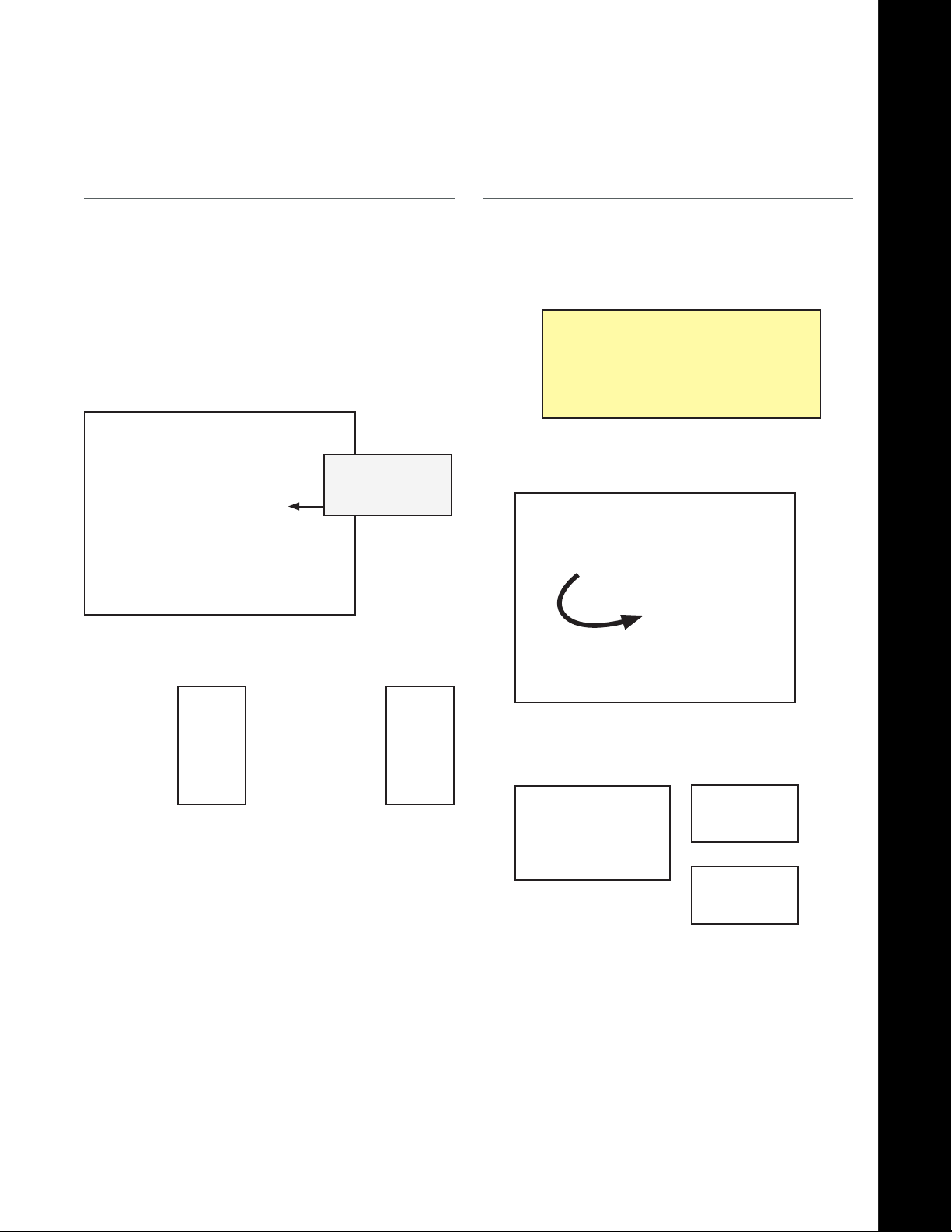
Getting Started
See the CD included in the VivoResponder™ kit to download
1.
VivoCommand Soware. If you misplaced or did not receive
your CD please call customer service.
When VivoCommand installation is completed, an icon is
2.
placed on the Desktop. Double click on it. e program takes
a moment to load.
e Main Session screen will open and looks like the picture
3.
below.
USB Base Station(s)
Plug in USB Base Station
A.
e Connection tab will be displayed. Select Local: using
B.
serial port. Click the <Port List> button.
Select
Click
Button
Click on <Mode>, then on <Site Setup>.
4.
e Site Setup pop-up window will open. e Connection
5.
tab will be displayed. Follow procedure for wither USB Base
Station(s) or Ethernet Base Station(s).
A window will open as shown below. Click <Show avail ports>
C.
which will open a pop-up. Jot down the COM#(s) then click <OK>.
Click
to nd opten
Type the COM# into the open eld. Multiple USB Base Station
D.
users enter each of the COM numbers into the open elds.
Enter the
COM#(s)
Release VMLA-177-00 Rev. 1
Click <Apply>, then <OK> to save the Port List.
E.
VivoCommand 00 Software
2

Getting Started
Ethernet Base Station(s)
With Ethernet Base Station, click Local: using TCP/IP and type the TCP/IP port into the eld
A.
next to Port: It is recommended to contact I.T. support.
Select
Enter the
e Simulator button may be selected to run a VivoCommand simulation,
B.
which is described in Testing the Set-up.
Automatically connect when VivoCommand is started can be checked if desired.
C.
In the Site Setup window, click on the second tab – <Directories> – and browse to the desired
D.
folder to store saved sessions and for the exported data. Leave the eld blank to store data in the
Application Folder. e C:\Program les\VivoMetrics\VivoCommand folder is the default.
Release VMLA-177-00 Rev. 1
VivoCommand 00 Software

Setting Preferences
Click on <Mode> on the Main Session screen and then
1.
choose Preferences.
pop-up will appear. Choose desired Zone colors. Graph
Back Lines and the Graph Background Color can also be
customized.
In this manual, the colors purple and light blue have been
4.
chosen as the default Zone colors. Click <OK>.
Click on the Colors tab. e default Zone colors are light and
2.
dark gray.
To change the Zone colors, click on the gray square and a
3.
Release VMLA-177-00 Rev. 1
Click on the Zones tab in the pop-up window. e maxi-
5.
mum and minimum values for each of the ve parameters—
Respiration, Heart Rate, Skin Temperature, Activity and
Posture—are the preset Default Zone Values.
VivoCommand 00 Software

Setting Preferences
To set Zone Values based on an individual’s
physiologic prole, it is recommended that the
following references be consulted:
http://www.acsm.org/Content/NavigationMenu/News/Othermedia/BooksCDs/Books_and_Multimedi.htm
ACSM’s Guidelines for Exercise Testing and Prescription,
Seventh Edition
(ISBN: 0-7817-4506-3)
Recommended for ACSM Certication Examinations!
e single most internationally read and referenced text in
sports medicine, exercise science, and health and tness. is
manual succinctly summarizes recommended procedures for
exercise testing and exercise prescription in healthy and diseased individuals. e Seventh Edition contains the most current public health and clinical information and state-of-theart, research-based recommendations. Coverage representsthe
fundamental knowledge, skills, and abilities (KSAs) that must
be mastered by candidates for all ACSM certications.
Written by international experts in numerous elds, the
Seventh Edition covers additional topics including arthritis, osteoporosis, dyslipidemia, immunology, and metabolic
syndrome.
To order: Call the ACSM Certication Resource Center at
Lippincott Williams & Wilkins at 1-800-486-5643
(outside the U.S. call 410-528-4185)
NOTE: e Zone Values input into these elds will automatically
be inserted when a new user is added. A user’s parameter cell
will change color if a dened Zone Value is reached. Zones are
described in detail in this manual.
In this manual, the following Zone Values have been set and are
6.
used as an example of how to set Defaults and Zone Values.
Click <OK>. Default colors and Zone Values are now set.
Also see:
Maryland Fire and Rescue Institute and Center for Fireghter
Safety Research and Development report, “Health and Safety
Guidelines for Fireghter Safety”
http://www.mfri.org/reresearch/hsg/healthandsafetyguidelines.pdf
See table on page 63 of the report (page 64 of the PDF)
Release VMLA-177-00 Rev. 1
VivoCommand 00 Software

Creating Groups and Users
is section describes how to prepare and customize
VivoCommand Soware.
Click on <Mode> on the Main Session screen and then
1.
choose Groups and Users.
You are now on the Groups and Users screen as shown below:
2.
Once the Group is named, enter the names of each team
4.
member in the cells in the Name column. Double click each
name eld to enter a name. Also enter the URB id – the
preprogrammed unique identier printed on the outside of
each Sensor Module that the named user is wearing. Up to
25 people can be entered, then further grouped by alphabetically dened Subgroup.
URB id
is on back of
Sensor Module RX
NOTE: As each name is entered, the Zone Values that were set in
previous Preferences section appear. Customizing zones for individual users is described in the next session: Zones.
Enter URB id
found on back of
Sensor Module RX
Sub-Group Group Name
Choose <Groups> and then New Group. A pop-up window
3.
appears with a eld to enter the name of the group. Enter
the Group name in the New Group popup window, and
then click <OK>.
Enter the
GROUP name
URB ID
Double click on
name cell to
enter new user
Users can be sorted by Subgroup and/or listed alphabetically
5.
using the buttons at the bottom of the Groups and Users
screen.
Swap Down
Selected Name
Swap Up
Selected Name
Alpha
Sort Users
Alpha Sort
Subgroups
Release VMLA-177-00 Rev. 1
VivoCommand 00 Software

Creating Groups and Users
ere are two ways to save your entries once each Group member’s name, URB id, and subgroup
6.
are entered and/or when you have made changes to an existing Group. All saved les will be
located in folder chosen under Site Setup/Directories.
Click on <Groups>, then <Save Changes>.
A.
Click the <Return> button to bring you back to the Main Session screen.
B.
File is automatically saved when you click.
RETURN
goes to
Main Session Screen
and auto-saves
Group & User Info
NOTE: When you click the Cancel button, you will return to the Main Session screen.
Data will not be saved.
NOTE: VivoCommand is designed for an innite number of saved Groups.
Only one Group can be active at a time.
Main Session Screen and
CANCEL
goes to
DOES NOT SAVE
Group & User Info
Release VMLA-177-00 Rev. 1
VivoCommand 00 Software
7

Zones
VivoCommand Soware monitors ve parameters: Breath Rate, Heart Rate, Skin Temperature, Activity, and Posture.
Breath Rate, Heart Rate, and Skin Temperature have four customizable zone values as shown below:
1.
Zone 1 Low and High (purple) and Zone 2 Low and High (blue). e center column is the average
between Zone 1 high and low levels. All are customizable for each user.
Breath
Rate
Activity has two Zone Values; both are customizable for each user.
2.
Posture has two Zone Values: standing upright and laying down.
3.
Heart
Rate
Select Parameter
(Breath Rate)
Skin
Temperature
Activity Posture
Zone Values
(Breath Rate)
Release VMLA-177-00 Rev. 1
VivoCommand 00 Software

Zones
Customizing Zones
Customized Zones can be set two ways:
1.
A. Enter a Number in the Cell:
Create a “crosshair” by clicking on a user’s row and one of the parameter columns. Double
click in one of the cells on the right side of the screen; type in the desired number. Repeat.
B. Use the Sliders:
Create a “crosshair” by clicking on a user’s row and one of the parameter columns. Drag each
of the four sliders located on the right side of the screen to set Zone Value. Sliders correspond
to zone columns and show graphically what the trend screen will look like. When a parameter
goes above or below the purple or blue line the cell in the Main Session screen will change to
purple or blue respectively.
e screen below shows an example of the Breath Rate Zone Value customized for an individual user.
Select
User’s Row
to change
Breath
Rate Zone
Value
BREATH RATE
Parameter Customized
Blue background links
user with slider feature
Type in cell to set
Zone Values
Use Sliders to set
Zone Values
Release VMLA-177-00 Rev. 1
VivoCommand 00 Software

Zones
To restore all users to the Zone Values created in Preferences, go to Groups and click on
2.
<Set Default Zone Values To All Members>. All users will be restored to those values.
When all zones have been customized, click on the <Return> button to go to the
3.
VivoCommand Main Session screen. Changes are automatically saved.
Click Return to
go to
Main Session
screen
NOTE: You can also save by click on Groups, then Save Changes. e Cancel button will also take you to
the Main Session screen, but changes are not saved.
Release VMLA-177-00 Rev. 1
VivoCommand 00 Software
0

Testing the Setup
ere are two ways to test the setup of VivoCommand Soware. Both use Session Mode, which
1.
is used to run live sessions once setup is complete:
A. Have 1 to 25 people put on the VivoResponder™ System.
B. Use the VivoCommand Simulator in Site Setup.
Aer names have been entered, parameters set, subgroups created, and all have been saved in
2.
Groups and Users mode, click the <Return> button, which goes to the Session screen.
e four main areas in Session mode: toolbar, bookmark, user, and graph are indicated below.
3.
When the system is not connected, the “LED” dots next to each name are red. Not connected is
also indicted in the lower le corner of the screen.
Toolbar Area
User Area
Not
Connected
Bookmark
Area
Graph Area
Release VMLA-177-00 Rev. 1
VivoCommand 00 Software
1

Testing the Setup
Toolbar Area
e Toolbar area starts and stops recording, checks posture
calibration prior to recording, and tracks the running time of a
session.
SESSION
RECORD
(not activated)
e Green Record button is used to begin recording a
1.
session. e button is green when ready to record. e
button is red when recording. Click on the <red button>
to stop the session.
Button is red when
recording. Click on it to
stop recording.
CALIBRATE
POSTURE
(Prior to Recording)
CLOCK
Optional: Use the CAL button to check if a user’s VivoRe-
6.
sponder™ posture has been calibrated correctly it will display
posture of all connected users without recording any data.
Before connecting to run a live session, all users should
»
be instructed to stand-up straight.
Click on the <CAL> button. As shown below, if a user
»
was not properly calibrated, the “LED” to the le of the
name turns orange and the posture icon indicates the
user is not standing upright.
If the user is standing upright but the posture
»
parameter indicates otherwise, the VivoResponder™
should be powered o and on to recalibrate while
the user is upright.
e session is automatically saved within the Group folder
2.
once every (1) second. e les are saved using the following
convention:
…\group_name\yyyy-mm-dd hh-mm-ss\…
A session is made of three les within the folder:
3.
e yyyy-mm-dd hh-mm-ss.urb le contains the
»
physio-data and is the tile that can be loaded to view the
session post event.
e groupsnapshot.ini le contains the group when the
»
recording was made.
e bookmarks.bmk le contains all Bookmark infor-
»
mation
e program cannot be closed while recording.
4.
While recording, the Clock will track the session length.
5.
Orange Dot
indicates
Calibration
not correct.
Recalibrate Vi-
voRsponder™
Posture
Calibration Activated
User is upright,
but is indicated
as not.
Release VMLA-177-00 Rev. 1
VivoCommand 00 Software
2

Testing the Setup
Bookmark Area
e Bookmark features can be used during a live session and on a recorded session.
ere are two ways to create a Bookmark.
1.
A. Click and release on the <blue ag> icon. e cursor will become a “ghost” outline of the ag.
Move it to the Graph area desired and click to create a Bookmark. e time of your Bookmark
appears in the pull-down Bookmark list in the center of the Bookmark area. is is a good way
to mark something unusual in the data.
B. Click on the <time eld> next to the blue ag. At the time of the click a Bookmark will ap-
pears in the Bookmark list in the center of the Bookmark area. is is useful to synchronize
with the start of an event.
Click Flag. Cursor
becomes “ghost”
ag. Position in
GRAPH area and
click to create a
Bookmark.
BOOKMARK List
pull-down
GO to selected
Bookmark
Opens Notepad
Deletes Bookmark
Click on black
CLOCK to set
Bookmark
A Bookmark is automatically created at time 0:00:00 for every session. is bookmark cannot be
2.
deleted. It is intended to be a place to enter session information and notes.
e ABC button opens a pop-up window with a Notepad that corresponds to a particular Book-
3.
mark from the pull-down list.
A. Text can be added by clicking in the window and typing during live recording and can be
added later into a saved sessions. Click <OK> to save.
Described in
GRAPH area
Click OK to save.
Release VMLA-177-00 Rev. 1
VivoCommand 00 Software

Testing the Setup
B. e graph, the header, as well as an item from a clipboard can also be pasted into the Notepad.
It can also be exported as a Microso Word .doc.
Paste From
Clipboard
Paste Graph
Use the Bookmark pull-down to search to time in the recorded Graph.
4.
Save as .DOC
Paste Header
A. When recording, select the desired Bookmark, then click <GO>.
GRAPH area
is live
Select desired
Bookmark from
pull-down
Click Go
Release VMLA-177-00 Rev. 1
VivoCommand 00 Software

Testing the Setup
B. e Graph area is will go oine, but the session will continue to be recorded.
GRAPH area is
off-line when box
is not checked
RESPIRATION
value & time
at
mouse location
When mouse is moved in the graph, the value of the Parameter and the time of that event are
5.
shown next to each Parameter.
Bookmark
Selected GRAPH
area set to that
time.
e ag with the X button deletes the selected Bookmark.
6.
Release VMLA-177-00 Rev. 1
VivoCommand 00 Software

Testing the Setup
User Area
e User Area shows the value for each of the ve parameters based
on Zone Values set in Groups and Users.
To display a specic user’s trend graphs select a user by
5.
clicking on the name cell or use the up/down arrows on your
keyboard. is changes the corresponding graphs on the
right side of the screen to the corresponding show real-time
data of the selected user.
User
Area
The selected User is
highlighted in blue,
which visually links to
the blue background of
the GRAPH area.
Graph
Area
Number of
Users connected.
Green dots
connection
Breath Rate, Heart Rate, and Skin Temperature are
1.
numerical; Activity and Posture are icons.
Vital sign data are updated every second.
2.
e background colors of the cells reect the Zone Values
3.
set for the user. If the background is white, then the value is
within mean/normal.
If the user is connected and no data is being received, the dot
4.
next to the name will turn yellow. If there is no data aer 10
seconds, the dot will turn red.
Selected User:
blue background
indicate
Change in
Background color
indicates reaching
set Zone Value
e highlighted user links to the Graph Area.
6.
Graph Area
e Graph Area shows the trend data of the last ve minutes of
the ve physiological parameters in a graphical manner for an
individual user.
Graphs are updated once every second.
1.
Preset color horizontal lines represent the Zone Values as set
2.
in Groups and Users. A user’s zones can be modied while
recording, but not when playing back a session.
To scroll through previous sensor data, uncheck the Graph
3.
Live button at the top of the Bookmark area. e Graph
Live checkbox is disabled in playback mode. e session will
continue to record. No data will be lost.
e top of the Graph area is used for Markers. Place mouse
4.
over location on graph to set a Marker and click the le and/or
right mouse button to set. e le marker is shown as a vertical
red line and the right marker by a blue line in the graph area.
e time of each marker is displayed and the duration between
the markers is automatically calculated.
Release VMLA-177-00 Rev. 1
VivoCommand 00 Software

Testing the Setup
Breath Rate
Heart Rate
Temperature
Mark with Left
Mouse Click
(red line & time)
Time between
Marks
Mark with Right
Mouse Click
(blue line & time)
Auto scales
each parameter
individuality
Reset removes
auto scaling
Zone 2: High
Zone 1: High
Zone 1: Low
Activity
Posture
Any chart can be scaled using dierent values than the default ones by moving the arrows of the
5.
dual sliders.
Values displayed with default scaling values:
»
Zone 2: Low
Scale Graph with
Dual Sliders
Scroll Saved
Session
Release VMLA-177-00 Rev. 1
VivoCommand 00 Software
7

Testing the Setup
If Auto is checked for each parameter, the scaling is set so
6.
that the values will t inside the Graph Area to the maximum size possible and the Sliders will disappear.
Same values with auto scaling:
»
Click on reset to set the scaling back to the default scal-
»
ing values.
To review a saved session, use the Scroll Bar at the bottom of
7.
the Graph area.
NOTE: If a user goes out of radio range, the graph will be drawn
with a gray line repeating the last known good value and the dot will
turn red.
To run the Simulator, go to Session and click on <Connect>.
3.
Simulator Mode:
Follow this Section as a Tutorial
Simulator mode is used to familiarize you with VivoCommand
Soware.
To activate the Simulator, click on <Mode>, then <Site
1.
Setup>
In the pop-up window, click <Simulator>, then <OK>.
2.
Click on the <green arrow> button. It will change to red.
4.
You should see simulated data starting to display in the
Graph area.
NOTE: If you have fewer than 25 users entered, you will see an error
message unknown URB’s… is is because the Simulator sends 25
sets of data. If you have 20 users in the eld, but only input 19 names,
this would warn you that the set-up is incomplete.
Test Your Understanding of How to Collect Data:
Set a Bookmark
»
Add a text note to the Bookmark
»
Go in and out of live mode
»
Scale the graphs
»
Reset a zone while live
»
Change the graph colors
»
Try every button
»
Stop the session
»
Disconnect
»
Release VMLA-177-00 Rev. 1
In the next section, you will learn how to export data.
VivoCommand 00 Software

Exporting
Live sessions or saved sessions can be exported in a few simple steps.
If the session is live, click <Stop>.
»
If the session is saved, go to Session, then Load Session, which will launch a pop-up window to
»
browse to where les are located. Click on the desired <.URB le> (created by live recording) or
<.RAW le> (created using the Data Logger – see the Data Logger Manual) to load.
Go to Session, then click <Export>.
»
e Export screen will look like this:
RETURN to
Session Mode
Group Name
Choose User
Name to
view and
select data
for export
(blue)
USERS
25 Max.
Click BOX or
use SELECT
NONE/ALL
to choose
Users to
EXPORT
File Name
Select PARAMETER to
view specic begin and
end points
BOOKMARK
To dene
Begin and
End
Browse
to change
location of
this saved
exported
session
Click once
to EXPORT
Release VMLA-177-00 Rev. 1
Enter Begin/End
times using
mouse left/right
or bookmarkst
Includes header with
le data in exported
.CSV le
VivoCommand 00 Software

Exporting
All or any users can be selected for export. By default, the
1.
les will contain all the recorded data.
Begin/End is the same for ALL users and can be modied in
2.
one of three ways:
Use the mouse le/right buttons
»
Select begin/end Bookmarks from the le/right list
»
boxes
Click on the <left/right> arrows.
»
Export mode creates COMMA DELIMITED (.csv) les that
3.
can easily be imported into MatLab or any statistical analysis
program or database.
e folder name is the date/time stamp of the session. All
4.
.csv les will be created under that folder. All les will be
named user_name.csv.
In the example above, six users were exported and the
5.
following les were created:
…\2006-09-26 15-23-18\Bodey Keller.csv
…\2006-09-26 15-23-18\Dan Smith.csv
…\2006-09-26 15-23-18\Jose Mizrahi.csv
…\2006-09-26 15-23-18\Max Reed.csv
…\2006-09-26 15-23-18\Sam Jones.csv
…\2006-09-26 15-23-18\Tom Young.csv
NOTE: e folder’s default location is set in Mode/Site Setup/
Directories or can be changed for one specic export on the Export
screen.
Click on one of the .csv les and it will launch Microso
6.
Excel.
Export .CSV—Column Headers
e chart below describes the columns in the .CSV export.
Col A .....Time .....................................In seconds from start of
recording to end
Col B .....Valid Packet ........................Either 0 = invalid or 1 = valid
Col C .....Sequence .............................1-255
Col D .....Valid Respiration ...............Either 0 = invalid or 1 = valid *
Col E ......Respiration average ...........Breath rate per minute
Col F ......Respiration Condence ....1-7 condence value that
respiration is accurate (7 being
100% condent)
Col G .....Valid Heart Rate ...................Either 0 = invalid or 1 = valid **
Col H .....Heat Rate Average .............Heart rate per minute
Col I .......Valid Skin Temp ................Either 0 = invalid or 1 = valid
Col J .......Skin Temp ...........................Temperature under the armpit
in Fahrenheit without the
decimal point
Col K .....Valid Ambient Temp ........Either 0 = invalid or 1 = valid
Col L ......Ambient Temp ...................Temperature on the PCB
inside the sensor module in
Centigrade without the
decimal point
Col M ....Valid Position .....................Either 0 = invalid or 1 = valid
Col N .....Position................................When calibrated (standing
upright when starting system
during green light ash) then
0 = upright and 250= upside
down
Col O .....Valid Activity .....................Either 0 = invalid or 1 = valid
Col P ......Activity ................................0 = stationary, 255= maximum
activity
*As the sensor module monitors the RIP band’s hardware, a “band OK” bit
reects the condition of a correct electrical band connection and reasonable
observed frequency range of the associated RIP oscillator. To reduce false
cycles, the RIP value trend is monitored and considers changes when the RIP
value slope value exceeds a pre determined 1st derivative level.
**A HR “OK bit” indicates pulses are being received from the Polar Wearlink
transmitter in the proper sequence, and that motion artifacts are within the
system recovery specs. is implies that the Polar Wearlink snaps are properly
connected, the fabric ECG patches are conducting, and the sensor circuit is
functional. e “OK” bit state is reective of these conditions:
1) HR values are tracking “smoothly”[1] and 8 or more valid beats have
been observed.
2) Motion artifact caused beats that are out of specs have not exceeded
32 consecutive beats to false plateau {2}
3) No single beat longer than 4 seconds is observed (considered same as
disconnected hardware)
[1] HR “smoothness” rule dictates that no instantaneous beat rate can
dier from the present average by more than 24BPM
[2] Sharp Transitions of HR are permitted if the new “non smooth”
incoming beats belong to a new baseline in which smoothness rule
is observed. is permits tracking of fast HR changes as might be
observed in a resting person standing up and jogging. e new HR
plateau should be seen in 32 beats to avoid being classied as motion
artifact
Release VMLA-177-00 Rev. 1
VivoCommand 00 Software
0

Loading a Saved File
Loading a Saved .URB
or Data Logger File
You can load a previously recorded les (.URB) or a data logger le
(.RAW) for review in VivoCommand and to export as a .CSV le.
Load a Saved .URB File
To load a .URB le, go to Session and click on <Load Session>
1.
A pop-up window will appear with the folder that was previ-
2.
ously chosen to save les. Click on the folder of the named
Group you wish to load, then select the Session to load.
e .URB Session le appears as below.
3.
Click on it and it will load this previously recorded Session in
4.
VivoCommand.
Selected
Group Folder
Session
Selected Folder
Release VMLA-177-00 Rev. 1
VivoCommand 00 Software
1

Loading a Saved File
Load a Data Logger .RAW File
Go to Session, then Load Session (same as shown above for .URB les)
1.
A pop-up window with your .RAW les will open. Click on the user you want to load and the
2.
File Conversion window will open.
Click <OK> and File Conversion will automatically change the .RAW to a .URB le, save to
3.
where you direct it, and launch the le in VivoCommand.
NOTE: Data Logger les can only be viewed one user at a time.
Release VMLA-177-00 Rev. 1
VivoCommand 00 Software
2

Troubleshooting / FAQ’s
What are the computer requirements to run VivoCommand?
PC with minimum requirements of:
Pentium 4, 1.5 GHz processor
»
512 Mgs RAM
»
60 Gig HD
»
USB/Ethernet ports
»
What version of VivoCommand am I using?
In the main toolbar, click on About. is will open a pop-up
window with information about the installed VivoCommand.
Authorized customers can download new versions.
I know that I am using a USB port, but when I entered the COM
number, the system did not work.
You do not have the correct serial port number. Go to the
Base Station tab and follow instructions regarding locating
the serial port(s) number(s).
Service
I used the CAL function to check the posture calibration of my
users and noticed that the icon shows one of them as lying down,
but I can see that the person is standing upright?
If the user is standing upright but the posture parameter indicates otherwise, the VivoResponder™ should be disconnected
from the Sensor Module, then plugged back in with Sensor
Module in the holster to recalibrate while the user is upright.
What types of les are generated?
- VivoCommand creates .URB les
- e Data Logger creates .RAW les
If VivoCommand requires warranty or non-warranty service,
please contact VivoMetrics Customer Support.
If you fax or email Customer Support, be sure to include your name
and a contact phone number or email, and a complete description
of the problem you encountered, including what you were doing
and what is not working properly.
Customer Support:
Telephone: 800-631-4445 (inside U.S.A.)
805-667-2225 (outside U.S.A.)
Fax: 805-667-6646
Email: help@vivometrics.com
Release VMLA-177-00 Rev. 1
VivoCommand 00 Software
 Loading...