

Page 1

VLHDMICTL1-MME
18G In-line HDMI Controller with Auto Display Control
All Rights Reserved
Version: VLHDMICTL1-MME_2019V1.1
User Manual
Page 2

18G In-line HDMI Controller with Auto Display Control
Preface
Read this user manual carefully before using the product. Pictures shown in this
manual are for reference only. Different models and specifications are subject to real
product.
This manual is only for operation instruction, please contact the local distributor for
maintenance assistance. The functions described in this version were updated till
March, 2019. In the constant effort to improve the product, we reserve the right to
make functions or parameters changes without notice or obligation. Please refer to the
dealers for the latest details.
FCC Statement
This equipment generates, uses and can radiate radio frequency energy and, if not
installed and used in accordance with the instructions, may cause harmful interference
to radio communications. It has been tested and found to comply with the limits for a
Class B digital device, pursuant to part 15 of the FCC Rules. These limits are designed
to provide reasonable protection against harmful interference in a commercial
installation.
Operation of this equipment in a residential area is likely to cause interference, in
which case the user at their own expense will be required to take whatever measures
may be necessary to correct the interference.
Any changes or modifications not expressly approved by the manufacture would void
the user’s authority to operate the equipment.
Page 3

18G In-line HDMI Controller with Auto Display Control
SAFETY PRECAUTIONS
To ensure the best performance from the product, please read all instructions carefully
before using the device. Save this manual for further reference.
Unpack the equipment carefully and save the original box and packing material for
possible future shipment.
Follow basic safety precautions to reduce the risk of fire, electrical shock and injury
to persons.
Do not dismantle the housing or modify the module. It may result in electrical shock
or burn.
Using supplies or parts not meeting the products’ specifications may cause damage,
deterioration or malfunction.
Refer all servicing to qualified service personnel.
To prevent fire or shock hazard, do not expose the unit to rain, moisture or install this
product near water.
Do not put any heavy items on the extension cable in case of extrusion.
Do not remove the housing of the device as opening or removing the housing may
expose you to dangerous voltage or other hazards.
Install the device in a place with fine ventilation to avoid damage caused by
overheat.
Keep the module away from liquids.
Spillage into the housing may result in fire, electrical shock, or equipment damage. If
an object or liquid falls or spills on to the housing, unplug the module immediately.
Do not twist or pull by force ends of the optical cable. It can cause malfunction.
Do not use liquid or aerosol cleaners to clean this unit. Always unplug the power to
the device before cleaning.
Unplug the power cord when left unused for a long period of time.
Information on disposal for scrapped devices: do not burn or mix with general
household waste, please treat them as normal electrical wastes.
Page 4

18G In-line HDMI Controller with Auto Display Control
Table of Contents
1. Product Introduction .................................................................................................... 1
1.1 Features ............................................................................................................ 1
1.2 Package List ...................................................................................................... 1
2. Technical Specification ................................................................................................ 2
3. Panel Description ................................................................ ................................ ........ 3
3.1 Front Panel ........................................................................................................ 3
3.2 Rear Panel ......................................................................................................... 4
4. System Connection ..................................................................................................... 5
4.1 Usage Precaution .............................................................................................. 5
4.2 System Diagram ................................................................................................ 5
5. DIP Switch Operation .................................................................................................. 6
5.1 EDID Management ............................................................................................ 6
5.2 HDCP Mode....................................................................................................... 8
6. System Control Setting ............................................................................................... 9
6.1 RS232 Command Setting ................................................................................ 10
6.1.1 RS232 Control Software ........................................................................ 10
6.1.2 Trigger Method Setting ................................ .......................................... 11
6.1.3 CEC Control Setting .............................................................................. 12
6.1.4 RS232 Control Setting ........................................................................... 12
6.1.5 IR Control Setting .................................................................................. 14
6.1.6 Relay Control Setting ............................................................................. 15
6.1.7 System Command ................................................................................. 16
6.2 Front Panel IR Learning ................................................................................... 16
7. Panel Drawing .......................................................................................................... 17
8. Troubleshooting & Maintenance ............................................................................... 18
9. Customer Service ..................................................................................................... 19
Page 5

18G In-line HDMI Controller with Auto Display Control
1
1. Product Introduction
Thanks for choosing the VLHDMICTL1-MME 18G In-line HDMI Controller, which is
designed for automatic system control and HDMI signal extension in small meeting
rooms and huddle spaces. The controller supports three system trigger methods, IR
signal, video signal (5V or TMDS). It automatically triggers CEC commands,
pre-loaded RS232 and IR commands to turn on or off display, and relay control to rise
and fall the projection screen. It supports video resolution up to 4K@60Hz 4:4:4 HDR
10 and Dolby Vision, and features 4K to 1080P down-scaling for compatibility with
1080P display. Besides passing EDID information from the display, there are multiple
built-in EDID settings can be selected by the 4-pin DIP switch on the front panel. In
addition, the controller supports CEC pass-through, RS232 control, IR learning and
relay control.
1.1 Features
Supports up to 4Kx2K@60Hz 4:4:4 HDR10 and Dolby Vision, HDCP 2.2 compliant.
HDCP pass-through or converted to HDCP 1.4 for better compatibility.
Supports 4K to1080P down-scaling.
Comprehensive EDID management with 8 EDID Options for various application.
Automation display control via CEC, RS232 and IR.
Contact Closure input for connections with a variety of devices, such as sensor and
switch.
Relay control for device like projection screen.
Built-in signal equalizer, provides capability to use longer range HDMI cable.
1.2 Package List
1x 18G In-line HDMI Controller
2x Mounting Ears with 4 Screws
4x Plastic Cushions
3x 3-pin Terminal Blocks
1x RS232 Cable (3-pin to DB9)
1x Power Adapter (5V DC 1A)
1x User Manual
Note: Please contact your distributor immediately if any damage or defect in the
components is found.
Page 6

18G In-line HDMI Controller with Auto Display Control
2
2. Technical Specification
Video Input
Input
(1) HDMI IN
Input Connector
(1) Female type-A HDMI
Input Video Resolution
Up to 4Kx2K@60Hz 4:4:4 8bit
Video Output
Output
(1) HDMI OUT/CEC
Output Connector
(1) Female type-A HDMI
Output Video Resolution
Up to 4Kx2K@60Hz 4:4:4 8bit
Control
Control
(1) SET Button, (1) 4-pin DIP Switch, (1) FW, (1) IR OUT,
(1) RS232, (1) Sensor, (2) Relay (1~2)
Control Connector
(1) Type-A USB, (1) 3.5mm mini jack, (4) 3-pin terminal blocks
General
HDMI Standard
2.0
HDCP Version
2.2
HDCP Pass-through
Supported
CEC Control
Supported
Hot-plug
Supported
Bandwidth
18Gbps
HDMI Cable Length
1080P@60Hz ≤ 33 feet (10 meters),
4K@60Hz ≤ 16 feet (5 meters)
Operation Temperature
-5℃ ~ +55℃
Storage Temperature
-25℃ ~ +70℃
Relative Humidity
10%-90%
Power Supply
Input:100V~240V AC; Output: 5V DC 1A
Power Consumption
2.5W(Max)
Dimension (W*H*D)
120mm x 28mm x 84mm
Net Weight
305g
Note: Please adopt high-qualified HDMI cable fully compliant with HDMI2.0 for reliable transmission
and connection.
Page 7

18G In-line HDMI Controller with Auto Display Control
3
3. Panel Description
3.1 Front Panel
① POWER LED: The LED illuminates green when power is applied.
② HDMI OUT LED: The LED illuminates blue when there is HDMI signal output.
③ SENSOR: Built-in IR sensor to receive IR signal.
④ DISPLAY ON LED: The LED blinks blue when the controller is in IR learning
mode, and it will illuminate blue after successfully learning the IR command.
⑤ DISPLAY OFF LED: The LED blinks blue when the controller is in IR learning
mode, and it will illuminate blue after successfully learning the IR command.
⑥ SET: Press the button to enable IR learning mode. Please refer to chapter 6.2 for
more details.
⑦ 4-pin DIP switch for EDID setting and HDCP mode selection.
⑧ FW: Type-A USB port for firmware upgrade.
HDMI OUT
FW
ON
OFF
1
0
1 2 3 4
IR LEARNING
DISPLAY
ON
SENSOR
SET
DISPLAY
OFF
1
2
3
4
5 6
7
8
Page 8
18G In-line HDMI Controller with Auto Display Control
4
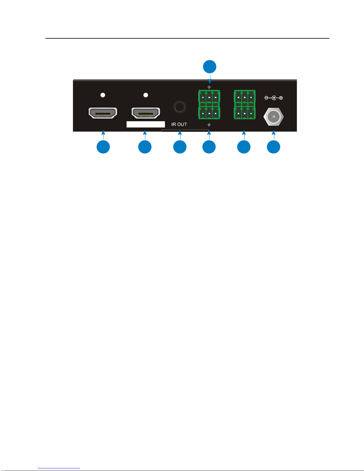
3.2 Rear Panel
① HDMI IN: Type-A female HDMI input port to connect HDMI source device.
② HDMI OUT/CEC: Supports CEC. Type-A female HDMI output port to connect
HDMI display.
③ IR OUT: 3.5mm mini jack to connect the IR emitter to send IR signal.
④ RS232: 3-pin terminal block to connect the RS232 control device (e.g. PC) or a
device (e.g. projector) to be controlled by RS232 commands.
⑤ Sensor: 3-pin terminal block to connect external sensor or switch.
⑥ Relay 1~2: Two 3-pin terminal blocks to connect projection screen for relay
control.
⑦ DC 5V: DC connector for the power adapter connection.
DC 5V
NO C NC
RS232
Sensor
Relay 1
Relay 2
12V Sig
HDMI IN
Tx Rx
NO C NC
HDMI OUT / CEC
1
2
3
4
7
5 6
Page 9

18G In-line HDMI Controller with Auto Display Control
5
4. System Connection
4.1 Usage Precaution
Make sure all components and accessories are included before installation.
System should be installed in a clean environment with proper temperature and
humidity.
All of the power switches, plugs, sockets, and power cords should be insulated and
safe.
All devices should be connected before power on.
4.2 System Diagram
The following diagram illustrates typical input and output connections that can be
utilized with this controller:
Page 10
18G In-line HDMI Controller with Auto Display Control
6
5. DIP Switch Operation
5.1 EDID Management
The Extended Display Identification Data (EDID) is used by the source device to
match its video resolution with the connected display. By default, the source device
obtains its EDID from the first connected display. Meanwhile, since the display with
different capabilities is connected to the controller, the DIP switch on the front panel
can be used to set the EDID to a fixed value to ensure the compatibility in video
resolution.
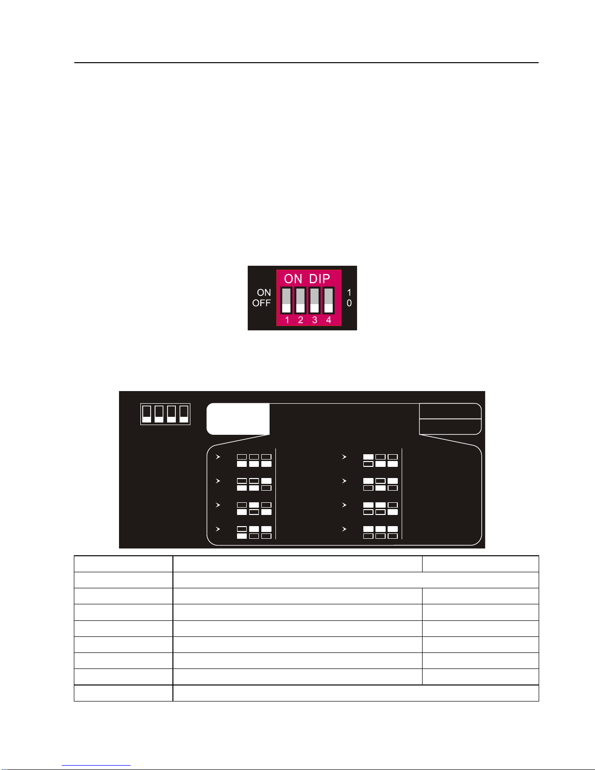
The switch represents “0” when in the lower (OFF) position, and it represents “1” while
putting the switch in the upper (ON) position.
Switch 1~3 are used for EDID setting. The DIP switch status and its corresponding
setting are shown at the back of the product.
Switch Status
Video Resolution
Audio Format
000
Pass Through
001
1080P
2CH
010
1080P
Multi-CH
011
3840x2160@30Hz HDR
2CH
100
3840x2160@30Hz HDR
Multi-CH
101
3840x2160@60Hz HDR
2CH
110
3840x2160@60Hz HDR
Multi-CH
111
User-defined EDID (Upload the EDID by type-A USB port)
1 2 3
EDID Setting
Default
1 2 3 4
ON
OFF
1
0
ON
OFF
4
HDCP Active
HDCP Passive
Pass Through
1080p 2CH
4K/30Hz HDR 2CH
ON
OFF
1 2 3
ON
OFF
1 2 3
ON
OFF
1 2 3
ON
OFF
1 2 3
1080p Multi-CH
ON
OFF
1 2 3
ON
OFF
1 2 3
ON
OFF
1 2 3
4K/30Hz HDR Multi-CH
4K/60Hz HDR 2CH
4K/60Hz HDR Multi-CH
ON
OFF
1 2 3
User Defined
Page 11

18G In-line HDMI Controller with Auto Display Control
7
Note:
2CH: Supports LPCM 2CH.
Multi-CH: Supports LPCM 8CH, Dolby TrueHD, DTS-HD , Dolby Digital5.1, DTS
5.1, Dolby Digital Plus.
User-defined EDID Setting
Except directly invoking the built-in EDID, the specific EDID can be customized by
following the below operation process.
1) Rename the user-defined EDID as EC_11.bin.
2) Connect the FW port of the controller to the PC with USB cable, and then power
on the controller, the PC will automatically detect a virtual disk named of
“BOOTDISK”.
3) Double-click to open the disk, a file named of “READY.TXT” will be showed.
4) Copy the user-defined EDID to the “BOOTDISK” disk.
5) Reopen the disk to check the filename “READY.TXT” whether automatically
becomes “SUCCESS.TXT”, if yes, the user-defined EDID was imported into the
controller and saved as its corresponding EDID ID successfully.
6) Remove the USB cable, and then reboot the controller.
7) Now the new EDID can be invoked by setting the DIP switch status to “111”.
Page 12

18G In-line HDMI Controller with Auto Display Control
8
5.2 HDCP Mode
Put switch 4 on “ON” position to select HDCP Active mode, or to “OFF” for HDCP
Passive mode.
Switch Status
Mode
HDCP
OFF (0)
Passive
(Default)
Automatically follows the HDCP version of source device.
ON (1)
Active
If the input video has HDCP content, the HDCP version of HDMI
output is HDCP 1.4 for broader video solution.
If the input video has no HDCP content, the HDMI output has no
HDCP either.
Page 13

18G In-line HDMI Controller with Auto Display Control
9
6. System Control Setting
SYSTEM ON
When the controller detects video signal (TMDS, 5V) or IR signal, the system will start
and automatically perform the below actions at the same time.
Send CEC ON to turn on display.
Send RS232 ON + Delay Time (default 3s, range of 1~180s) + User-defined
RS232 command to display.
Send IR ON + Delay Time (default 3s, range of 1~180s) + User-defined IR
command to display.
Toggle the state of relay 1 as follow.
I/O State
Relay State
NO
NC
On (Closed)
Closed
Open
Off (Open)
Open
Closed
SYSTEM OFF
When the controller detects all input source devices are removed, or not receives IR
signal within the delay time (default 10mins, range of 5mins-180mins), the system will
off and automatically perform the below actions at the same time.
Send CEC OFF to turn off display.
Send RS232 OFF to display. The number of sending command is default 1 time, it
can be set to 2 times by RS232 command.
Send IR OFF to display. The number of sending command is default 1 time, it can
be set to 2 times by RS232 command.
Toggle the state of relay 2.
Page 14

18G In-line HDMI Controller with Auto Display Control
10
6.1 RS232 Command Setting
The trigger methods of SYSTEM ON or SYSTEM OFF, and CEC, RS232, IR, Relay
control actions can be set by RS232 commands.
6.1.1 RS232 Control Software
Installation: Copy the control software file to the PC which is connected to the
controller.
Uninstallation: Delete all the control software files in corresponding file path.
Here take the software CommWatch.exe as example. Double-click the following icon:
The interface of the control software is shown as below:
Parameter configuration area
Monitoring area, indicates if the
command sent works.
Command sending area
Page 15

18G In-line HDMI Controller with Auto Display Control
11
Please set the parameters of COM number, bound rate, data bit, stop bit and the parity
bit correctly, then the RS232 commands can be sent in Command Sending Area.
Baud rate: 9600;
Data bit: 8;
Stop bit: 1;
Parity bit: none.
6.1.2 Trigger Method Setting
Command
Function
Feedback Example
SYSONMETH[X].
Set the trigger method to perform
SYSTEM ON.
X
Description
0
Detects IR signal
1
Detects HDMI video signal
(default 5V, or TMDS)
2
Detects IR or video signal
SYSONMETH1.
SET DETECT VIDEO TRIGGER!
SYSOFFMETH[X].
Set the trigger method to perform
SYSTEM OFF.
X
Description
0
Detects no IR signal
1
Detects no HDMI video
signal (default 5V, or TMDS)
2
Detects no IR and video
signal
SYSOFFMETH1.
SET NOT DETECT VIDEO
TRIGGER!
NOSIGDLY:[XXXXX].
Set the system off time to xxxxx (default
10mins, range of 5mins to 180mins).
When no HDMI video signal has been
detected, the system will off after the
setting time.
NOSIGDLY:00300.
SET DETECT NOSIGNAL DELAY
TIME 300S!
NOIRDLY:[XXXXX].
Set the system off time to xxxxx (default
10mins, range of 5mins to 180mins).
When no IR signal has been detected,
NOIRDLY:00300.
SET DETECT NO IR DELAY TIME
Page 16

18G In-line HDMI Controller with Auto Display Control
12
the system will off after the setting time.
300S!
5VORTMDS[X].
Set the HDMI video signal trigger
condition.
X
Description
0
Detects 5V signal.
1
Detects TMDS signal.
5VORTMDS0.
DETECT INPUT SOURCE USE
5V!
GSYSONMETH.
Report the trigger method of SYSTEM
ON.
DETECT VIDEO TRIGGER IN
SYSTEM ON!
GSYSOFFMETH.
Report the trigger method of SYSTEM
OFF.
NO DETECT VIDEO TRIGGER IN
SYSTEM OFF!
GNOSIGDLY.
Report the delay time of SYSTEM OFF
when the controller detects no input
source signal (5V/TMDS).
DETECT NOSIGNAL DELAY
TIME 300S!
GNOIRDLY.
Report the delay time of SYSTEM OFF
when the controller detects no IR sensor
signal.
DETECT NO IR DELAY TIME
300S!
G5VORTMDS.
Report the detection method of input
source. 5V/TMDS
DETECT INPUT SOURCE USE
5V!
6.1.3 CEC Control Setting
Command
Function
Feedback Example
CECON.
Enable CEC.
OPEN CEC FUNCTION!
CECOFF.
Disable CEC.
CLOSE CEC FUNCTION!
GCECSTAUS.
Report CEC status.
CEC FUNCTION IS OPEN!
TVON.
Turn on display (e.g. TV)
CEC TV POWER ON!
TVOFF.
Turn off display (e.g. TV)
CEC TV POWER OFF!
6.1.4 RS232 Control Setting
Command
Function
Feedback Example
RS232ON/+[X]:XXX
When detects triggering signal,
automatically send ASCII command XXX
to the third-party device (e.g. Projector)
whose baud rate is X.
X
Baud Rate
1
2400
RS232ON/+3:123abc
Page 17

18G In-line HDMI Controller with Auto Display Control
13
2
4800
3
9600
4
19200
5
38400
6
57600
7
115200
Send the ASCII command
“123abc” to the third-party whose
baud rate is 9600.
RS232ON/-[X]:XXX
When detects triggering signal,
automatically send HEX command XXX
to the third-party device (e.g. Projector)
whose baud rate is X.
RS232ON/-3:30 31 32
Send the HEX command “30 31
32” to the third-party whose baud
rate is 9600.
RS232OFF/+[X]:XXX
When does not detect any triggering
signal, automatically send ASCII
command XXX to the third-party device
(e.g. Projector) whose baud rate is X.
RS232OFF/+3:123abc
Send the ASCII command
“123abc” to the third-party whose
baud rate is 9600.
RS232OFF/-[X]:XXX
When does not detect any triggering
signal, automatically send HEX command
XXX to the third-party device (e.g.
Projector) whose baud rate is X.
RS232OFF/-3:30 31 32
Send the HEX command “30 31
32” to the third-party whose baud
rate is 9600.
RS232U/+[X]:XXX
Set the user-defined ASCII command to
send to the third-party device (e.g.
Projector) whose baud rate is X.
RS232USER/+3:123abc
Send the user-defined command
“123abc” to the third-party whose
baud rate is 9600.
RS232U/-[X]:XXX
Set the user-defined HEX command to
send to the third-party device (e.g.
Projector) whose baud rate is X.
RS232USER/-3:30 31 32
Send the user-defined command
“30 31 32” to the third-party whose
baud rate is 9600.
RS232DLY:[XXX].
Set the sending interval time between
RS232 ON and RS232 USER to XXX
(default 3s, range of 1S to 180s).
RS232DLY:003.
SET DELAY TIME BETWEEN
RS232 ON AND RS232 USER 3S!
RS232PCS[X].
Set the sending number of RS232 OFF to
X.
X
Description
0
1 time
1
2 times
SET SEND RS232 OFF TWO
TIME!
RS232OFFINT:[XX].
Set the two times sending interval time of
RS232OFFINT:02.
Page 18

18G In-line HDMI Controller with Auto Display Control
14
RS232 OFF to XX (default 2s, range of
1S to 10s).
SET RS232 OFF SEND DELAY
TIME 2S!
GRS232DLY.
Report the sending interval time between
RS232 ON and RS232 USER.
DELAY TIME BETWEEN RS232
ON AND RS232 USER 3S!
GRS232PCS.
Report the sending number of RS232
OFF
SEND RS232 OFF ONE TIME!
GRS232OFFINT.
Report the two times sending interval
time of RS232 OFF.
RS232 OFF SEND DELAY TIME
2S!
6.1.5 IR Control Setting
Command
Function
Feedback Example
IRSTUDY[X].
Learns the IR command from IR remote.
X
Description
0
STUDY IR DISPLAY
OFF
1
STUDY IR DISPLAY ON
2
STUDY IR USER
IRSTUDY0.
READY STUDY IR DISPLAY
OFF,PLEASE REMOTE
CONTROL RECEIVER IN 10S!
IRSEND[X].
Send the learned IR command.
X
Description
0
SEND IR DISPLAY OFF
1
SEND IR DISPLAY ON
2
SEND IR USER
IRSEND0.
SEND IR DISPLAY OFF!
IRDLY:[XXX].
Set the sending interval time between IR
ON and IR USER to XXX (default 3s,
range of 1S to 180s).
IRDLY:003.
SET DELAY TIME BETWEEN IR
ON AND IR USER 3S!
IRPCS[X].
Set the sending number of IR OFF to X.
X
Description
0
1 time
1
2 times
IRPCS1.
SET SEND IR OFF TWO TIMES!
IROFFINT:[XX].
Set the two times sending interval time of
IR OFF to XX (default 2s, range of 1S to
10s).
IROFFINT:02.
SET IR OFF SEND DELAY TIME
2S!
GIRDLY.
Report the sending interval time between
IR ON and IR USER.
DELAY TIME BETWEEN IR ON
AND IR USER 3S!
GIRPCS.
Report the sending number of IR OFF.
SEND IR OFF ONE TIMES!
Page 19

18G In-line HDMI Controller with Auto Display Control
15
GIROFFINT.
Report the two times sending interval
time of IR OFF.
IR OFF SEND DELAY TIME 2S!
6.1.6 Relay Control Setting
Command
Function
Feedback Example
RELAY1COT:[XXX].
Set the Relay 1 delay time to XXX
(default 10s, range of 3S to 180s).
RELAY1COT:010.
SET RELAY 1 TIME DELAY TIME
10S!
RELAY2COT:[XXX].
Set the Relay 2 delay time to XXX
(default 10s, range of 3S to 180s).
RELAY2COT:010.
SET RELAY 2 TIME DELAY TIME
10S!
GRELAY1COT.
Report Relay 1 delay time.
RELAY 1 TIME DELAY TIME 10S!
GRELAY2COT.
Report Relay 2 delay time.
RELAY 2 TIME DELAY TIME 10S!
Relay Port Definition
When the controller start SYSTEM ON, the Relay 1 port will perform the below actions:
1) The NO connection closes, and NC connection opens.
2) When the delay time is up, the NO connection opens, and NC connection closes.
When the controller start SYSTEM OFF, the Relay 2 port will perform the below
actions:
1) The NO connection closes, and NC connection opens.
2) When the delay time is up, the NO connection opens, and NC connection closes.
NO C NC
Relay 1
Relay 2
NO C NC
Page 20

18G In-line HDMI Controller with Auto Display Control
16
6.1.7 System Command
Command
Function
Feedback Example
RST.
Factory reset.
Factory Default!
SCALERON.
Enable 4K to1080P down-scaling
function.
OPEN DOWN SCALER
FUNCTION!
SCALEROFF.
Disable 4K to1080P down-scaling
function.
Close Down Scaler Function!
GDOWNSCALER.
Report down-scaling status.
DOWN SCALER FUNCTION IS
CLOSE!
GALLINFO.
Report all device information.
…
GEDIDMODE.
Report EDID.
EDID:PASS THROUGH
GHDCPMODE.
Report HDCP mode.
HDCP:PASSIVE!
6.2 Front Panel IR Learning
Besides configuring IR control by RS232 commands. The IR commands can be
learned from IR remote by the SET button on the front panel.
Please according the below steps to learn IR commands from IR remote:
Step 1: Press SET to choose DISPLAY ON or DISPLAY OFF command to be set.
DISPLAY ON LED: Flashing indicates that DISPLAY ON mode is selected.
DISPLAY OFF LED: Flashing indicates that DISPLAY OFF mode is selected.
Step 2: Point the IR remote at the SENSOR and press the respective button on the IR
remote.
Step 3: The DISPLAY ON or DISPLAY OFF LED will stop flashing and remain lit to
indicate that IR command has been learnt.
Step 4: Press and hold the SET button for 5 seconds can learn user-defined IR
command, and both DISPLAY ON and DISPLAY OFF LEDs are flashing. Then repeat
the step 2 and both LEDs will stop flashing and remain lit to indicate that IR command
has been learnt.
Step 5: The IR learning mode will self-terminate after 10 seconds of inactivity. Both the
DISPLAY ON and DISPLAY OFF LEDs go out to exit the IR learning mode.
IR LEARNING
DISPLAY
ON
SENSOR
SET
DISPLAY
OFF
Page 21

18G In-line HDMI Controller with Auto Display Control
17
7. Panel Drawing
DC 5V
NO C NC
RS232
Sensor
Relay 1
Relay 2
12V Sig
HDMI IN
Tx Rx
NO C NC
HDMI OUT / CEC
84.0mm
120.0mm
28.0mm
HDMI OUT
FW
ON
OFF
1
0
1 2 3 4
IR LEARNIN G
DISPLAY
ON
SENSOR
SET
DISPLAY
OFF
Page 22

18G In-line HDMI Controller with Auto Display Control
18
8. Troubleshooting & Maintenance
Problems
Potential Causes
Solutions
Colour losing or no video signal
output in HDMI display.
The connecting cables may not
be connected correctly or it may
be broken.
Check whether the cables are
connected correctly and in
working condition.
No signal output in this switcher
while local input is in normal
working state.
Splash screen in output devices.
Poor quality of the connecting
cable.
Change for another cable of
good quality.
Cannot control this controller by
control device (e.g. a PC)
through RS232 port.
Wrong RS232 communication
parameters.
Make sure the RS232
communication parameters are
correct.
This switcher is broken.
Send it to authorized dealer for
repairing.
Note: If your problem still remaining after following the above troubleshooting steps,
please contact your local dealer or distributor for further assistance.
Page 23

18G In-line HDMI Controller with Auto Display Control
19
9. Customer Service
The return of a product to our Customer Service implies the full agreement of the
terms and conditions hereinafter. There terms and conditions may be changed without
prior notice.
1) Warranty
The limited warranty period of the product is fixed three years.
2) Scope
These terms and conditions of Customer Service apply to the customer service
provided for the products or any other items sold by authorized distributor only.
3) Warranty Exclusion:
Warranty expiration.
Factory applied serial number has been altered or removed from the product.
Damage, deterioration or malfunction caused by:
Normal wear and tear.
Use of supplies or parts not meeting our specifications.
No certificate or invoice as the proof of warranty.
The product model showed on the warranty card does not match with the
model of the product for repairing or had been altered.
Damage caused by force majeure.
Servicing not authorized by distributor.
Any other causes which does not relate to a product defect.
Shipping fees, installation or labor charges for installation or setup of the product.
4) Documentation:
Customer Service will accept defective product(s) in the scope of warranty
coverage at the sole condition that the defeat has been clearly defined, and upon
reception of the documents or copy of invoice, indicating the date of purchase, the
type of product, the serial number, and the name of distributor.
Remarks: Please contact your local distributor for further assistance or solutions.
 Loading...