

VL12K12-BULK1V-EU-4K
User Manual
Multi-function AV Distribution System
All Rights Reserved
Version: VL12K12-BULK1V-EU-4K_2019V1.0

Multi-function AV Distribution System
Preface
Read this user manual carefully before using the product. Pictures shown in this
manual are for reference only. Different models and specifications are subject to real
product.
This manual is only for operation instruction, please contact the local distributor for
maintenance assistance. The functions described in this version were updated till April,
2019. In the constant effort to improve the product, we reserve the right to make
functions or parameters changes without notice or obligation. Please refer to the
dealers for the latest details.
FCC Statement
This equipment generates, uses and can radiate radio frequency energy and, if not
installed and used in accordance with the instructions, may cause harmful interference
to radio communications. It has been tested and found to comply with the limits for a
Class B digital device, pursuant to part 15 of the FCC Rules. These limits are designed
to provide reasonable protection against harmful interference in a commercial
installation.
Operation of this equipment in a residential area is likely to cause interference, in which
case the user at their own expense will be required to take whatever measures may be
necessary to correct the interference.
Any changes or modifications not expressly approved by the manufacture would void
the user’s authority to operate the equipment.

Multi-function AV Distribution System
SAFETY PRECAUTIONS
To ensure the best from the product, please read all instructions carefully before using
the device. Save this manual for further reference.
Unpack the equipment carefully and save the original box and packing material
for possible future shipment.
Follow basic safety precautions to reduce the risk of fire, electrical shock and
injury to persons.
Do not dismantle the housing or modify the module. It may result in electrical
shock or burn.
Using supplies or parts not meeting the products’ specifications may cause
damage, deterioration or malfunction.
Refer all servicing to qualified service personnel.
To prevent fire or shock hazard, do not expose the unit to rain, moisture or install
this product near water.
Do not put any heavy items on the extension cable in case of extrusion.
Do not remove the housing of the device as opening or removing housing may
expose you to dangerous voltage or other hazards.
Install the device in a place with fine ventilation to avoid damage caused by
overheat.
Keep the module away from liquids.
Spillage into the housing may result in fire, electrical shock, or equipment
damage. If an object or liquid falls or spills on to the housing, unplug the module
immediately.
Do not twist or pull by force ends of the cable. It can cause malfunction.
Do not use liquid or aerosol cleaners to clean this unit. Always unplug the power
to the device before cleaning.
Unplug the power cord when left unused for a long period of time.
Information on disposal for scrapped devices: do not burn or mix with general
household waste, please treat them as normal electrical wastes.

Multi-function AV Distribution System
Table of Contents
1. Product Introduction .................................................................................................... 1
1.1 Features ............................................................................................................ 1
1.2 Package List ...................................................................................................... 2
2. Specification ............................................................................................................... 3
2.1 K12-TX1V-EU-4K Transmitter ............................................................................ 3
2.2 K12-RX1-4K Receiver ....................................................................................... 4
2.3 K12-PAD1V-EU Control Panel ........................................................................... 5
3. Panel Description ........................................................................................................ 6
3.1 K12-TX1V-EU-4K Transmitter ............................................................................ 6
3.2 K12-RX1-4K Receiver ....................................................................................... 7
3.3 K12-PAD1V-EU Control Panel ........................................................................... 9
4. System Connection ................................................................................................... 11
4.1 Usage Precaution ............................................................................................ 11
4.2 System Diagram .............................................................................................. 11
4.3 Speaker Wiring Configurations ........................................................................ 12
4.4 PoC Connection .............................................................................................. 13
4.5 USB Connection .............................................................................................. 13
4.6 IR Connection .................................................................................................. 14
4.7 RS232 Connection .......................................................................................... 15
5. System Operation ..................................................................................................... 16
5.1 IR Learning ...................................................................................................... 16
5.2 Button Control .................................................................................................. 17
5.3 GUI Control ...................................................................................................... 18
5.3.1 Device Control Tab ................................................................................ 19
5.3.2 Setting Tab ............................................................................................. 20
5.3.3 Command Tab (RS232 Display Control) ................................................ 21
5.3.4 Configuration Tab .................................................................................. 23
5.3.5 Network Tab ........................................................................................... 24
5.3.6 GUI Update............................................................................................ 25
5.4 Copy and Load Control Settings ...................................................................... 26
6. Panel Drawing .......................................................................................................... 27
7. Troubleshooting & Maintenance ............................................................................... 29
8. Customer Service ..................................................................................................... 31

Multi-function AV Distribution System
1. Product Introduction
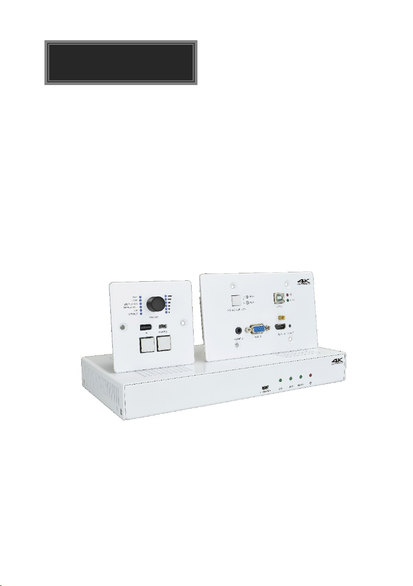
The VL12K12-BULK1V-EU-4K is a multi-function AV distribution system designed to
provide video switching, system control, video extension and analog audio
amplification in a convenient kit. The system consists of K12-TX1V-EU-4K HDBaseT
Transmitter, K12-RX1-4K HDBaseT Receiver and K12-PAD1V-EU Control Panel.
Utilizing the Valens Colligo series chips, power, control, video up to 4K, and audio are
transported over a single 40m (131ft)/70m (230ft) solid core Category cable between
the wall plate transmitter and the receiver. The wall plate control panel connects to the
wall plate transmitter with a second solid core Category cable. All the power needed for
the system is provided by the receiver. Additionally, the receiver features a built-in web
GUI for control and analog audio de-embedding to a built-in 2x20 watt stereo amplifier.
1.1 Features
Switch freely between HDMI and VGA signal input.
HDMI video resolution is up to 4Kx2K@60Hz 4:2:0.
Extends 4K@60Hz 4:2:0 signal up to 40m (131ft) and 1080p@60Hz signal up to
70m (230ft) via a single CATx cable.
When VGA source is selected as input, the output resolution can be selected as
1024x768, 1280x720, 1280x800, 1360x768, 1600x1200, 1920x1080, or
1920x1200.
USB for smart board connection.
Supports MIC input.
2x20Watt@4Ohm amplifier output.
Customizable control panel, support IR learning.
Copy and load IR and RS232 control settings.
Supports GUI control.
Supports UPNP.
Micro USB for firmware upgrade.
1

Multi-function AV Distribution System
Transmitter
1x K12-TX1V-EU-4K Scaler Wall Plate HDBaseT Transmitter
Receiver
1x K12-RX1-4K HDBaseT Receiver
2x Mounting Ears with 4 Screws
4x Plastic Cushions
1x 4-pin Terminal Block
3x 3-pin Terminal Blocks
1x 2-pin Terminal Block
1x IR Emitter
1x USB-A to USB-B Cable
1x Power Adapter (DC 24V 2.71A)
Control Panel
1x K12-PAD1V-EU Control Panel
1 x User Manual
1.2 Package List
Note: Please contact your distributor immediately if any damage or defect in the
components is found.
2

Multi-function AV Distribution System
Video & Audio
Video Input
(1) HDMI IN, (1) VGA IN
Video Input Connector
(1) 19-pin type-A female HDMI, (1) DB15 female VGA
Video Output
(1) PoC IN/HDBT OUT, (1) POWER/RS232
Video Output Connector
(2) RJ45
Audio Input
(1) AUDIO IN
Audio Input Connector
(1) 3.5mm mini jack
Control
Control Port
(1) TO PC, (1) FIRMWARE
Control Connector
(1) Type-B USB, (1) Micro USB
General
HDMI Video Resolution
Up to 4Kx2K@60Hz 4:2:0
VGA Video Resolution
Up to 1080p@60Hz
Output Resolution
(VGA Input)
1024x768, 1280x720, 1280x800, 1360x768, 1600x1200,
1920x1080, or 1920x1200 can be selected.
Transmission Mode
HDBaseT
Transmission Distance
CAT5e/6:
4K@60Hz 4:2:0 ≤ 35 meters (115 feet),
1080p@60Hz ≤ 60 meters (197 feet)
CAT6a/7:
4K@60Hz 4:2:0 ≤ 40 meters (131 feet),
1080p@60Hz ≤ 70 meters (230 feet)
Bandwidth
10.2Gbps
HDMI Version
1.4
Operation Temperature
-5~ +55℃
Storage Temperature
-25 ~ +70℃
Relative Humidity
10%-90%
Dimension (W*H*D)
151mm x 80mm x 47mm
Net Weight
268g
2. Specification
2.1 K12-TX1V-EU-4K Transmitter
3

Multi-function AV Distribution System
Video
Video Input
(1) HDBT IN/PoC
Video Input Connector
(1) RJ45
Video Output
(1) TO DISPLAY
Video Output Connector
(1) 19-pin type-A female HDMI
Audio
Audio Input
(1) MIC
Audio Input Connector
(1) 3-pin terminal block
Audio Output
(1) 2x20Watt@4Ω, (1) LINE OUT
Audio Output Connector
(1) 4-pin terminal block, (1) 3-pin terminal block
Audio Format
HDMI embedded audio: PCM/Dolby/DTS
MIC input audio: PCM
Analog output audio: PCM
Control
Control
(1) TCP/IP, (1) FROM TOUCHSCREEN, (1) IR OUT, (1) RS232,
(1) REMOTE MUTE
Control Connector
(1) RJ45, (1) Type-A USB, (1) 3.5mm mini jack, (1) 3-pin terminal
block, (1) 2-pin terminal block
General
Video Resolution
Up to 4Kx2K@60Hz 4:2:0
Transmission Mode
HDBaseT
Transmission Distance
CAT5e/6:
4K@60Hz 4:2:0 ≤ 35 meters (115 feet),
1080p@60Hz ≤ 60 meters (197 feet)
CAT6a/7:
4K@60Hz 4:2:0 ≤ 40 meters (131 feet),
1080p@60Hz ≤ 70 meters (230 feet)
Bandwidth
10.2Gbps
HDMI Version
1.4
Power Supply
Input:100V~240V AC; Output: 24V DC 2.71A
Power Consumption
55W (Max)
Operation Temperature
-5~ +55℃
Storage Temperature
-25 ~ +70℃
Relative Humidity
10%-90%
2.2 K12-RX1-4K Receiver
4
Multi-function AV Distribution System
Dimension (W*H*D)
250mm x 31mm x 130mm
Net Weight
682g
Port
Program Port
(1) CONFIG, (1) POWER/RS232
Output Port
(1) Type-A USB, (1) RJ45
Other
(1) Volume Knob, (2) Buttons (SOURCE, DISPLAY ON/OFF),
(1) Built-in IR sensor
Operation Temperature
-5~ +55℃
Storage Temperature
-25 ~ +70℃
Relative Humidity
10%-90%
Dimension (W*H*D)
80mm x 80mm x 37mm
Net Weight
124g
2.3 K12-PAD1V-EU Control Panel
5

Multi-function AV Distribution System
RESET
LINK
SOURCE S ELECT
VGA IN HDMI IN
TO PC
AUDIO IN
HDMI
VGA
PoC IN
HDBT OUT RS232
POWER
FIRMWA RE
5 6
11
12
4
13
1
7
8 9 10
2
3
3. Panel Description
3.1 K12-TX1V-EU-4K Transmitter
① SOURCE SELECT: Blue-backlit button for source selection.
② HDMI IN LED: The LED illuminates yellow when the HDMI source device is
connected to the HDMI input port. It will turn green when the HDMI source is
selected as input.
③ VGA IN LED: The LED illuminates yellow when the VGA source device is
connected to the VGA input port. It will turn green when the VGA source is selected
as input.
④ TO PC: Type-B USB to connect Host PC to receive USB control signal from
receiver.
⑤ POWER LED: The LED illuminates red when power is applied.
⑥ LINK LED: The LED illuminates green when there is a valid HDBaseT connection
with the receiver. The LED is off when there is no valid link.
⑦ AUDIO IN: 3.5mm mini jack to connect an external audio source device for VGA
video.
⑧ VGA IN: DB15 female VGA input port to connect a VGA source device.
⑨ HDMI IN: Type-A female HDMI input port to connect an HDMI source device.
⑩ RESET: Press this button to reboot the transmitter.
⑪ POWER/RS232: RJ45 port to connect the POWER/RS232 port on the control
panel via CATx cable to receive RS232 control signal and power the control panel.
6

Multi-function AV Distribution System
HDBT IN /PoC TO DISP LAY
RL
LINE OU TIR OUT
DC 24V
TCP/ IP TOUCH SCREEN
FROM
RS232
Tx Rx
OUTPU T CONT ROL MICNETWO RK
INPU T
MIC
2x20 Watt 4@
Ω
MICLINE
REMOT E
MUTE
AUDIO
ON L INK HDCP
FIRMWA RE
1
10
11
12
13
14 15
4
5
6
7
8
9
2
3
⑫ PoC IN/HDBT OUT: RJ45 port to connect the HDBT IN/PoC port of receiver by
CATx cable. The transmitter can be powered by this port once the receiver has
been powered up.
⑬ FIRMWARE: Micro-USB port for firmware upgrade.
3.2 K12-RX1-4K Receiver
① FIRMWARE: Micro-USB port for firmware upgrade.
② LED indicators:
ON: The LED illuminates green when the system is in normal working status.
LINK: The LED illuminates green when there is a valid HDBaseT connection
with the transmitter. The LED is off when there is no valid link.
HDCP: The LED illuminates green when there is HDMI video traffic with HDCP.
It will blink green when there is HDMI video traffic without HDCP and will be off
when there is no HDMI video traffic.
③ POWER LED: The LED illuminates red when power is applied.
④ TCP/IP: RJ45 port to connect the control device (e.g. PC) to control the system by
GUI.
⑤ HDBT IN/PoC: RJ45 port to connect the PoC IN/HDBT OUT port of transmitter by
CATx cable.
⑥ TO DISPLAY: Type-A female HDMI output port to connect a display device (e.g.
Projector).
7

Multi-function AV Distribution System
⑦ FROM TOUHSCREEN: Type-A USB port to connect a touch screen device (e.g.
Smart Board) to transmit USB signal back to the Host PC. The port also can be
connected to an interactive projector to achieve on-line handwriting annotation, but
it can’t be synchronized to the Host PC.
⑧ IR OUT: 3.5mm mini jack to connect IR emitter to control the display device.
⑨ RS232: 3-pin terminal block to connect the display device (e.g. Projector) for
RS232 control.
⑩ REMOTE MUTE: 3-pin terminal block to connect the fire alarm system. When the
fire alarm signal input, the audio output will be set to mute.
⑪ LINE OUT: 3-pin terminal block to connect an audio broadcast device to output
HDMI embedded audio and MIC audio in mixed mode. In additional, the port can
be connected to a sound recorder for sound recording.
⑫ LINE/MIC Level Selector Switch:
When the switch turns to “MIC”, the microphone input is connected to dynamic
microphone. There are two different connections:
1) Unbalanced connection:
“╧” connects to ground, and “-” connects to signal.
2) Balanced connection:
“+” connects to positive, “-” connects to negative and “╧” connects to ground.
When the switch turns to “LINE”, the microphone input is connected to normal
or wireless microphone. There are two different connections:
1) Unbalanced connection:
“╧” connects to ground, and “-” connects to signal.
2) Balanced connection:
“+” connects to positive, “-” connects to negative and “╧” connects to ground.
⑬ MIC: 3-pin terminal block to connect wireless microphone and compatible with MIC
and LINE audio. When connect PC or other audio input device besides
microphone, only “-”and “ ” pins need to be used.
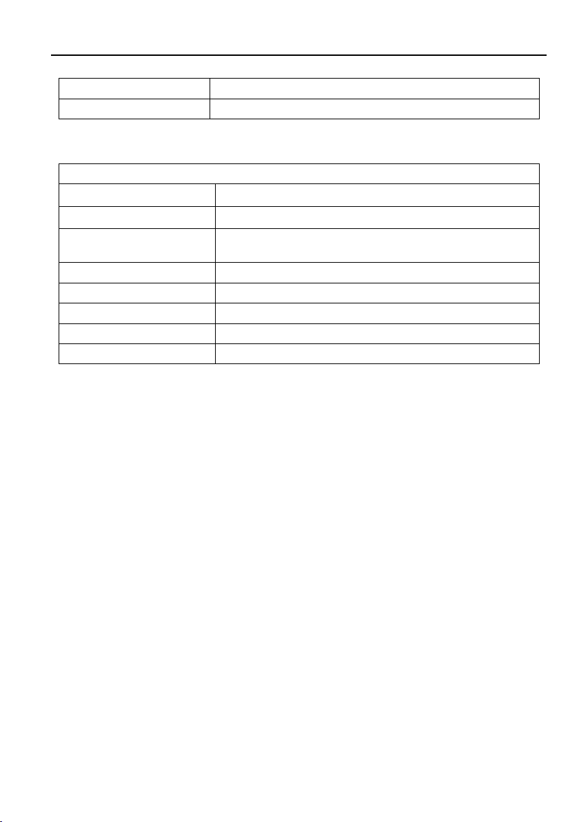
⑭ 2x20Watt@4Ω: 4-pin terminal block to connect speakers for audio mixing output.
⑮ DC 24V: Power port for power adapter connection.
8

Multi-function AV Distribution System
POWER
RS232
FIRMWARE
1
2
7
8
4
5 6
3
3.3 K12-PAD1V-EU Control Panel
① LED indicators:
VGA: The LED illuminates blue when the VGA source is selected.
HDMI: The LED illuminates blue when the HDMI source is selected.
DISPLAY ON: The LED illuminates blue when DISPLAY ON function is
selected by pressing DISPLAY ON/OFF button.
DISPLAY OFF: The LED illuminates blue when DISPLAY OFF function is
selected by pressing DISPLAY ON/OFF button.
MIC: The LED illuminates blue when the MIC audio is selected to be adjusted.
SOURCE: The LED illuminates blue when the source audio is selected to be
adjusted.
② VOLUME: Press and hold this button for three seconds to select MIC or SOURCE
audio to be adjusted. Rotate the button to turn up or turn down the selected audio.
Press the button to mute or unmute the current audio source.
③ IR: Built-in IR senor to receive IR signal from IR remote.
④ SOURCE: Blue-backlit button for source selection.
⑤ DISPLAY ON/OFF: Blue-backlit button. It can be programed by IR learning to turn
on or off the display device.
⑥ CONFIG: Type-A USB port to connect U-disk to copy or load control settings.
9

Multi-function AV Distribution System
⑦ POWER/RS232: RJ45 port to connect the POWER/RS232 port of the transmitter
via CATx cable to transmits RS232 control signal and power the control panel.
⑧ FIRMWARE: Micro-USB port for firmware upgrade.
10

Multi-function AV Distribution System
RESET
LINK
SOURCE SELE CT
VGA IN HDMI IN
TO PC
AUDIO IN
HDMI
VGA
Fir e A lar m
Sys te m
Proj ector
POWER
RS232
TCP IP/USB
CAT 5e 6 A C able 30m/
Smar t Boa rd
USB
IR
RS2 32
S
t
a
n
d
b
y
Wire less Mic
RS2 32
Lapt op Lapt op Lapt op
4. System Connection
4.1 Usage Precaution
Make sure all components and accessories are included before installation.
System should be installed in a clean environment with proper temperature and
humidity.
All of the power switches, plugs, sockets, and power cords should be insulated and
safe.
All devices should be connected before power on.
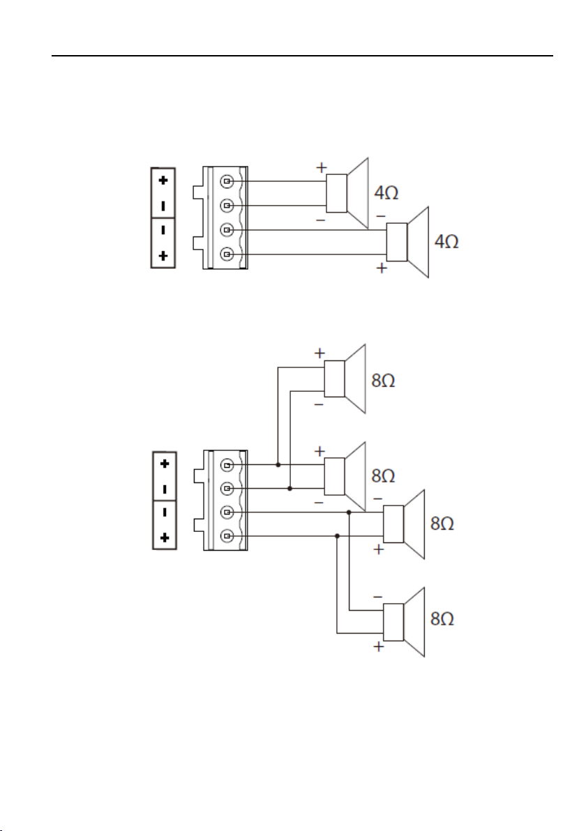
4.2 System Diagram
Note:
Connect HDBT ports via straight-thru CAT5e/6 cable with TIA/EIAT568B standard
terminations at both ends.
The distance is less than 40m at 4K or 70m at 1080p between transmitter and
receiver.
11
Multi-function AV Distribution System
4.3 Speaker Wiring Configurations
4Ω Load with 4Ω speakers:
4Ω Load with 8Ω Speakers:
12
Multi-function AV Distribution System
RESET
LINK
SOURCE SELE CT
VGA IN HDMI IN
TO PC
AUDIO IN
HDMI
VGA
POWER
RS232
CAT 5e/ 6A Ca ble 30m
24V 2 .71A
RESET
LINK
SOURCE SELECT
VGA IN HDMI IN
TO PC
AUDIO IN
HDMI
VGA
Proj ector
USB
CAT 5e/ 6A Ca ble 30m
Smar t Board
USB
Lapt op
4.4 PoC Connection
The system supports PoC, which allows several terminals share the same power
supply and eliminates the need for extra power supply at the remote nodes.
Connect a 24V DC power adapter to the power port of receiver, the transmitter and
control panel can be energized synchronously with PoC solution, see the picture below:
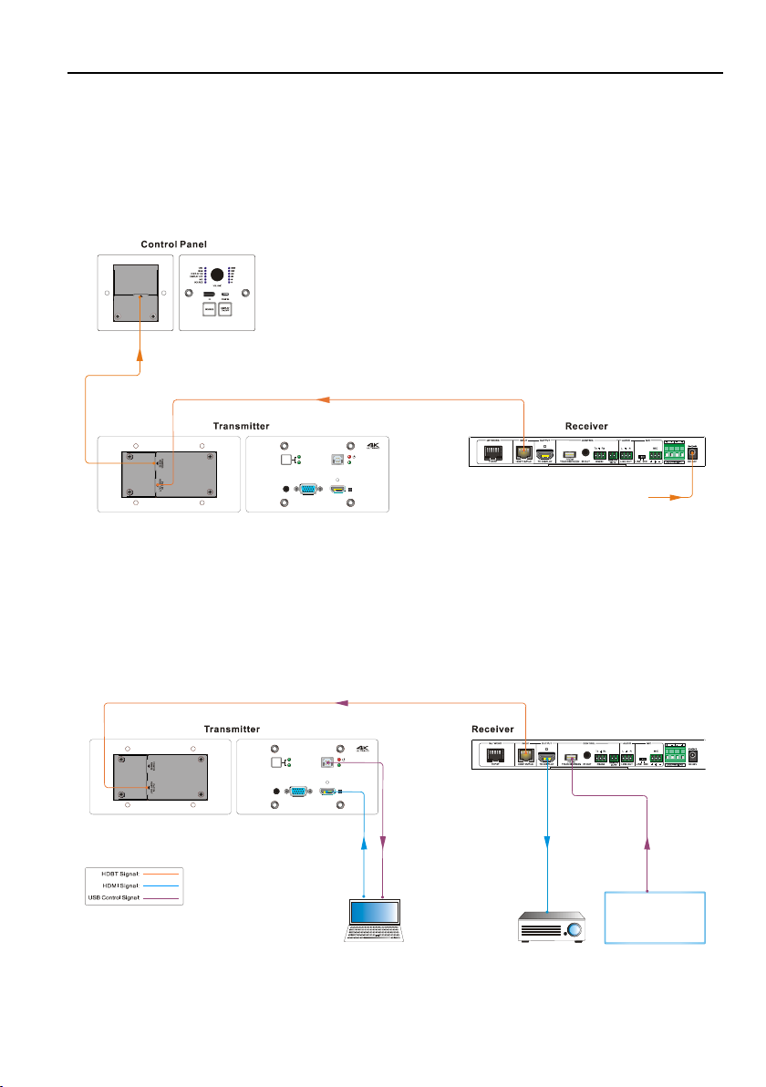
4.5 USB Connection
The receiver has a USB port (FROM TOUCH SCREEN) to connect smart board. When
user make notes on smart board, the receiver will receive the signal from smart board
and send it back to the Host PC. Please refer to the return path of USB signal as
shown as below.
Note: The special USB control cable is required if the connection distance is more than
13

Multi-function AV Distribution System
RESET
LINK
SOURCE SELECT
VGA IN HDMI IN
TO PC
AUDIO IN
HDMI
VGA
POWER
RS232
Proj ector
IR Si gnal
IR Si gnal
S
t
a
n
d
b
y
IR Si gnal
Lapt op
4m/13ft between the receiver and the smart board.
4.6 IR Connection
The control panel provides a built-in IR sensor and the receiver provides an IR OUT
port for IR pass-through control. Connect IR emitter to the IR OUT port of the receiver,
and then put the IR emitter close to the display device (e.g. Projector), and put the IR
remote of display device close to the built-in IR sensor, the display device can be
controlled by pressing IR remote.
14
Multi-function AV Distribution System
RESET
LINK
SOURCE SELEC T
VGA IN HDMI IN
TO PC
AUDIO IN
HDMI
VGA
Proj ector
TCP /IP
CAT 5e/ 6A Ca ble 30m
RS2 32
RS2 32
Lapt op Lapto p
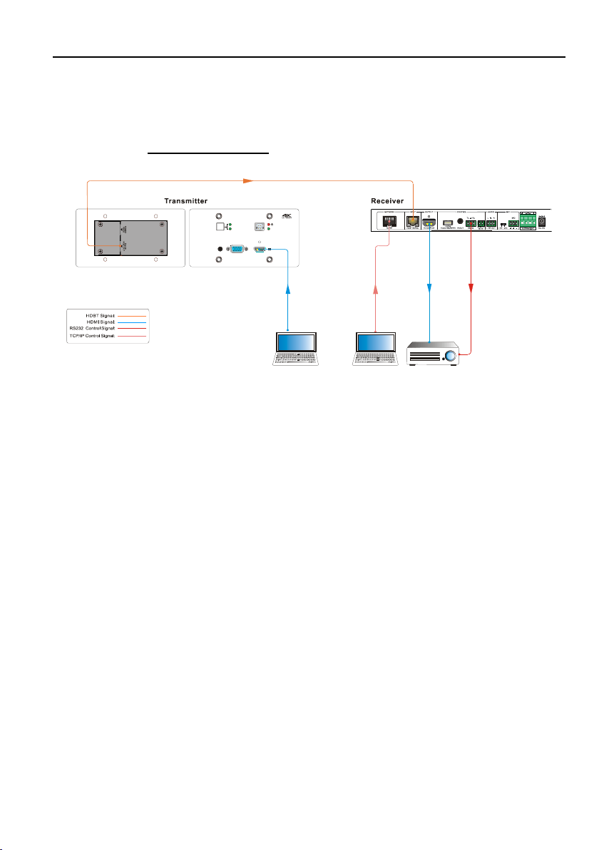
4.7 RS232 Connection
The receiver provides an additional RS232 interface to connect the display device, and
then the display device can be controlled by sending RS232 commands via GUI.
Please refer to 5.3.3 Command Tab.
15

Multi-function AV Distribution System
5. System Operation
5.1 IR Learning
The IR learning function allows user to use the buttons of control panel to displace
some keys of IR remote which can control display device or other devices. The control
panel has two buttons: SOURCE and DISPLAY ON/OFF, but the SOURCE button
does not support IR learning function, because it is designed for source selection.
Enter IR Learning Mode
Simultaneously press SOURCE and DISPLAY ON/OFF buttons to enter IR learning
mode. These two buttons will light up, and the DISPLAY ON and DISPLAY OFF LEDs
will start to flash.
Programming the DISPLAY ON and DISPLAY OFF Functions
1) Press DISPLAY ON/OFF button to choose DISPLAY ON or DISPLAY OFF
button function, and its corresponding LED will light blue. For example, press
DISPLAY ON/OFF button to choose DISPLAY ON button function, and the
DISPLAY ON LED lights blue.
2) Press the corresponding key (such as power on key) on IR remote; meanwhile,
put IR remote close to the IR sensor of control panel.
3) Once set up successfully, the DISPLAY ON LED will flash three times.
4) Repeat the above all three steps to set another DISPLAY OFF button function.
Exit IR Learning Mode
Press the SOURCE button to exit IR learning mode, and this button will go dark.
Apply IR Learning Function
Press the DISPLAY ON/OFF button on control panel to turn on display, and then press
this button again to turn off display device.
Note:
When the control panel is in the IR learning mode, press SOURCE button can exit.
If there is no operation for sixty seconds, the control panel will automatically exit the
IR learning mode.
All buttons will go dark while the control panel exits IR learning mode successfully.
16

Multi-function AV Distribution System
5.2 Button Control
Select Input Source
Press the SOURCE button on the control panel to select the appropriate source
device.
Press the SOURCE SELECT button on the transmitter to switch input signal
between HDMI and VGA sources.
Power On and Off the Display
When power on the display, press the DISPLAY ON/OFF button on the control
panel.
When power off the display, press the DISPLAY ON/OFF button on the control
panel.
Power On and Off the System
There are two modes for controlling display device and system: synchronous and
asynchronous control mode, which can be selected via GUI. For more details,
please refer to the 5.3.2 Setting Tab.
1) Synchronous mode:
Press the DISPLAY ON/OFF button on control panel to turn on or off the display
device and system concurrently.
2) Asynchronous mode:
Press the DISPLAY ON/OFF button on control panel to turn on or off the display
device.
Press and hold the DISPLAY ON/OFF button to power on or off system.
Volume Control
Turn the volume knob clockwise will raise the volume; turning the volume knob
counterclockwise will lower the volume.
Press the volume knob will mute or unmute the current audio source.
Press and hold the volume knob for three seconds will switch to the other audio
source. If the audio source is muted, this action will unmute the source.
17
Multi-function AV Distribution System
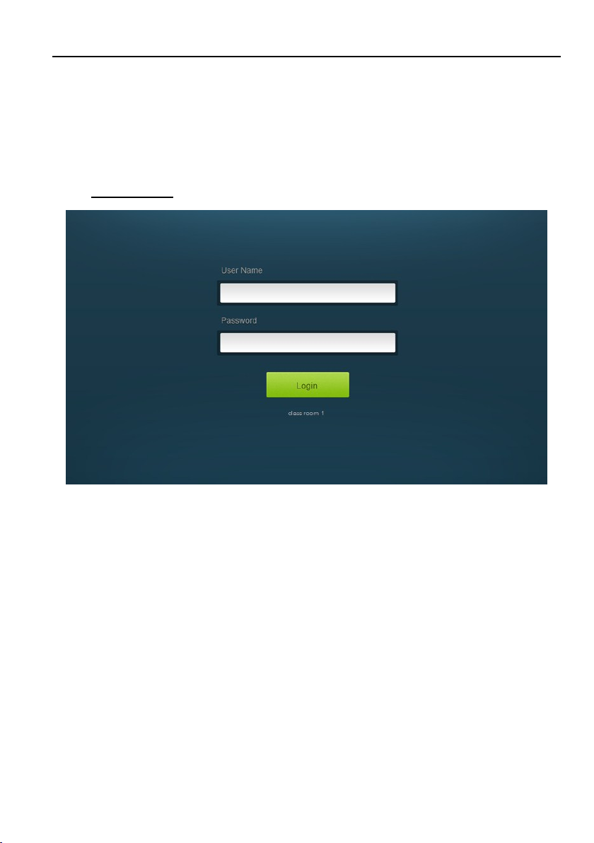
5.3 GUI Control
The web browser control interface is an alternative method to control the system
without having to interact with the control panel.
The default IP address of the transmitter is 192.168.0.178. This can be changed in the
Network settings by an administrator.
Type 192.168.0.178 in your browser, it will enter the log-in interface shown as below:
To change the settings of the web browser interface or program RS232 commands for
the display device, it requires log into the transmitter as an administrator. The User
Name is admin and the default Password is admin.
18
Multi-function AV Distribution System
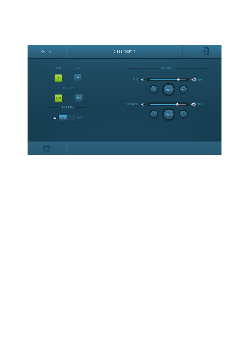
5.3.1 Device Control Tab
HDMI & VGA
Switch between HDMI and VGA.
DISPLAY
Turn the display on or off.
SYSTEM
Turn the system on or off.
VOLUME
Mute or unmute MIC and SOURCE audio. Volume may be changed by pressing the “+”
or “-” buttons or by dragging the volume slider.
Note: When you use IPad to click the “+” or “-”, it is a normal phenomenon that the
Mute button will shake.
19
Multi-function AV Distribution System
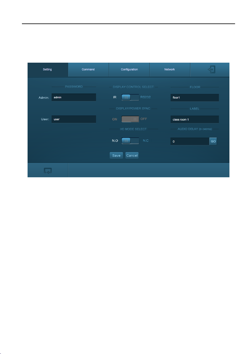
5.3.2 Setting Tab
To enter the configuration settings, click on the gear icon on the lower left corner of the
control interface.
PASSWORD
Change the password for the admin and user login screen.
DISPLAY CONTROL SELECT
Select whether the display will be controlled via IR or RS232.
DISPLAY/POWER SYNC
Select whether the display and system will be powered on and off simultaneously. This
option is only active if the display device is controlled via RS232.
When the mode is ON, press the DISPLAY ON/OFF button on control panel to turn
on or off the display device and system concurrently.
When the mode is OFF, press the DISPLAY ON/OFF button on control panel to turn
on or off the display device; press and hold the button to power on or off system.
I/O MODE SELECT
Enable (N.O.)/ disable (N.C.) fire alarm signal input.
20
Multi-function AV Distribution System
FLOOR
Rename the label at the control system.
LABEL
Rename the label at the top of the control screen.
AUDIO DELAY
Set up the audio delay to sync the audio with the video on the display device. The
delay time is 0 to 340 ms. Click the GO button to activate the new value.
Save/Cancel
Save or cancel setting.
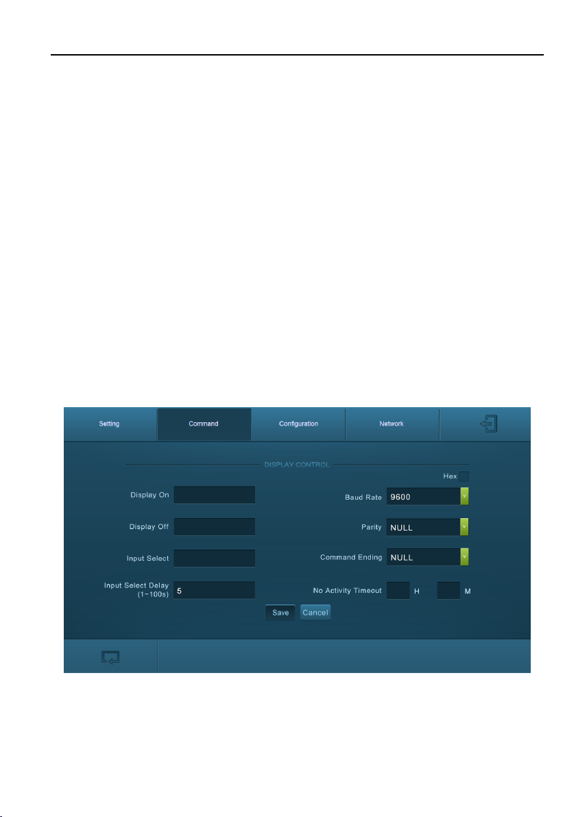
5.3.3 Command Tab (RS232 Display Control)
This tab defines the RS232 display control commands. If a display device requires Hex
commands, make sure the Hex box is checked.
21

Multi-function AV Distribution System
Display On
Enter the RS232 command to turn on the display.
Display Off
Enter the RS232 command to turn off the display.
Input Select
Enter the RS232 command to switch to the input which is connected to the receiver.
Input Select Delay
Enter the delay time in seconds between the Power On and Input Select commands.
This delay may be between 1 and 100 seconds.
Baud Rate
Select the baud rate necessary to communicate with the display. Available baud rates
are: 2400, 4800, 9600, 14400, 19200, 38400, 56000, 57600, and 115200 baud.
Parity
Select parity for RS232 communication.
Command Ending
Select the command ending for each RS232 command. Available command endings are:
null, carriage return, line feed, carriage return and line feed.
No Activity Timeout
The system will enter standby, and the display will automatic shutdown when no signal
input within the setup time.
22

Multi-function AV Distribution System
Save/Cancel
Save or cancel setting.
Note: Please refer to the display device’s user manual for more command details.
5.3.4 Configuration Tab
OUTPUT RESOLUTION
When VGA source is selected as input, the output resolution supports 1024x768,
1280x720, 1280x800, 1360x768, 1600x1200, 1920x1080 and 1920x1200 to be
selected.
FIRMWARE
Copy firmware file to one U-disk, and then insert the U-disk into the FIRMWARE port of
the transmitter, and click FIRMWARE to start update process.
23

Multi-function AV Distribution System
5.3.5 Network Tab
DHCP/STATIC IP
Select whether the system will use a static IP or will be provided an IP via DHCP.
IP Address
Enter the IP address for the system.
Subnet Mask
Enter the subnet mask for the system.
Gateway
Enter the gateway address for the system.
Confirm/Cancel
Save or cancel setting.
24

Multi-function AV Distribution System
5.3.6 GUI Update
Please visit at http://192.168.0.178:100 for GUI online upgrade.
Type the username and password (the same as the GUI log-in setting, modified
password will be available only after rebooting) to login the configuration interface. After
that, click Administration in the source menu to get to Upload Firmware as shown
below:
Select the desired update file and press Apply, it will start upgrading then.
25

Multi-function AV Distribution System
5.4 Copy and Load Control Settings
The system IR or RS232 configuration can be copied to a USB thumb drive and loaded
into additional systems or be saved as a backup.
Copy Control Setting
1) Insert a 4GB or smaller FAT32 formatted thumb drive into the CONFIG port on
the control panel.
2) Press and hold SOURCE for five seconds on control panel until all buttons start
to flash.
3) Press DISPLAY ON/OFF on control panel, and the button will light up while the
copy is in process.
4) Remove the thumb drive from the CONFIG port once all buttons go dark.
Load Control Setting
1) Insert a 4GB or smaller FAT32 formatted thumb drive with saved configuration
settings into the CONFIG port on the control panel.
2) Press and hold SOURCE for five seconds on control panel until all buttons start
to flash.
3) Press SOURCE on control panel, and the button will light up while the upload is
in process.
4) Remove the thumb drive from the CONFIG port once all buttons go dark.
5) Enter the Command Tab via GUI, the loaded RS232 commands will be showed,
and then press Save to confirm them.
26

6. Panel Drawing
RESET
LINK
SOURCE S ELECT
VGA IN HDMI IN
TO PC
AUDIO IN
HDMI
VGA
FIRMWAR E
151 mm (5.94 in)
80 mm( 3.15i n)
100 mm (3.94 in)
49 mm( 1.93i n)
47 mm( 1.85i n)
44 mm( 1.73i n)
HDBT IN/P oC T O DISPL AY
RL
LINE OUTIR OUT
DC 24V
TCP/IP TOUCHSC REEN
FROM
RS232
Tx Rx
OUTPUT CONTRO L MICNETWOR K
INPUT
MIC
2x20Wat t 4@
Ω
MICLINE
REMOTE
MUTE
AUDIO
130. 00 mm
31.0 0 mm
250. 00 mm
ON LINK HD CP
FIRMWARE
Multi-function AV Distribution System
K12-TX1V-EU-4K Transmitter
K12-RX1-4K Receiver
27

Multi-function AV Distribution System
POWER
RS232
FIRMWARE
80 mm ( 3.15i n)
80 mm ( 3.15i n)
60 mm (2.36 in)
48 mm (1.89 in)
37 mm (1.46 in)
34 mm (1.34 in)
K12-PAD1V-EU Control Panel
28
Multi-function AV Distribution System
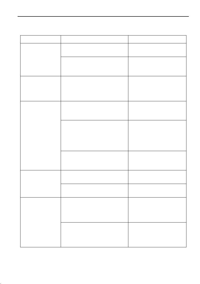
Problems
Potential Cases
Solutions
No reaction to any
operation, power
indicator is off
Haven’t been powered on.
Insert power adapter to the
receiver.
The poor quality of network
cable.
Should the replacement
CAT5e/CAT6a cable of high
quality.
POWER indicator
doesn’t work or no
respond to any
operation
Loose or failed power cord
connection
Ensure the power cord
connection is good.
Color lose or poor
picture quality
Signal loss caused by long
transmission distance beyond
effective value.
Make sure the connecting
cable is within 30m and of
good quality.
Bad quality of the HDMI cable.
Ensure the HDMI cables
used at source, transmitter,
receiver and display are
properly connected and are
of good quality.
HDMI cables are too long to
transmit high-resolution HDMI
signal successfully.
Shorten the length of HDMI
cables.
No video output
Communication cables has no
connection or bad connection.
Recheck all cables and
ports.
The display that you use is
incompatible with this device.
It is recommended that you
use mainstream display.
No audio output
Input source and output device
are connected to the wrong
ports.
Check again and make
sure input source and
output device are
connected correctly.
Audio output device don’t
support the audio format.
Change for other output
devices that support the
audio formats listed in
Specifications.
7. Troubleshooting & Maintenance
29
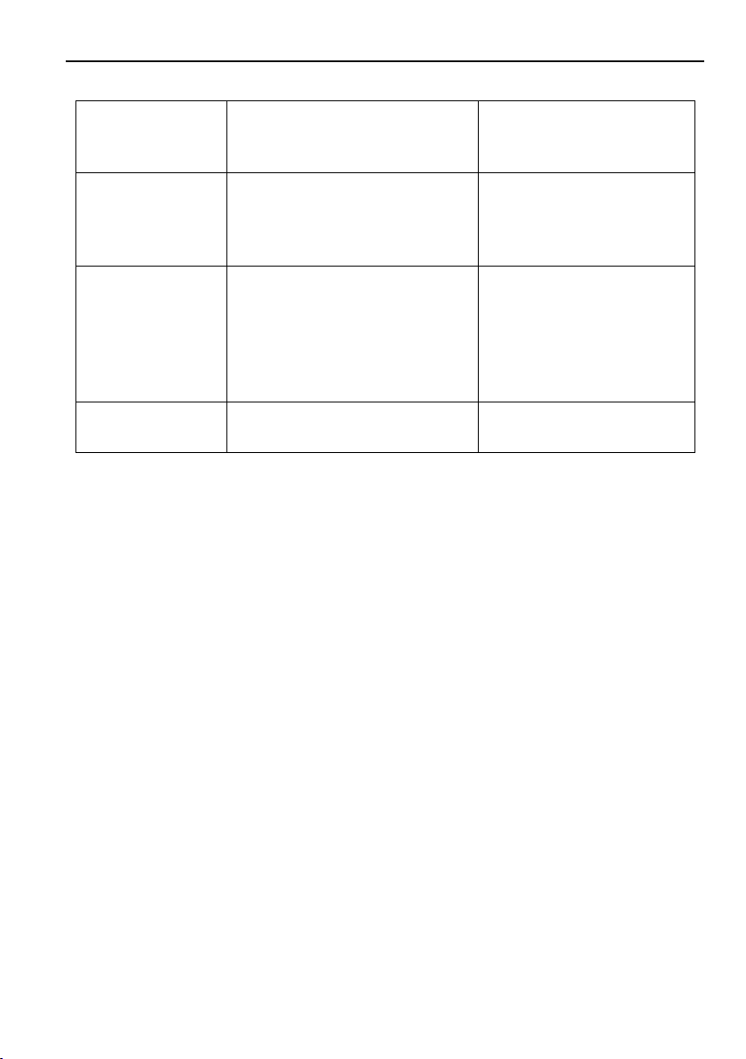
Multi-function AV Distribution System
Unable to login to
GUI
The PC’s network segment has
not been modified.
The PC’s network segment
need to be set as the same
as the kit’s
Static becomes
stronger when
connecting the
video connectors
bad grounding
Check the grounding and
make sure it is connected
well.
Cannot control the
projector by
control device
(e.g. a PC)
through RS232
port
Wrong RS232 communication
parameters
Make sure the RS232
communication parameters
are correct.
Cannot use the
device
the device is broken
Send it to authorized dealer
for repairing.
Note: If your problem still remaining after following the above troubleshooting steps,
please find further assistance.
30

Multi-function AV Distribution System
8. Customer Service
The return of a product to our Customer Service implies the full agreement of the terms
and conditions hereinafter. There terms and conditions may be changed without prior
notice.
1) Warranty
The limited warranty period of the product is fixed three years.
2) Scope
These terms and conditions of Customer Service apply to the customer service
provided for the products or any other items sold by authorized distributor only.
3) Warranty Exclusion
Warranty expiration.
Factory applied serial number has been altered or removed from the product.
Damage, deterioration or malfunction caused by:
Normal wear and tear.
Use of supplies or parts not meeting our specifications.
No certificate or invoice as the proof of warranty.
The product model showed on the warranty card does not match with the
model of the product for repairing or had been altered.
Damage caused by force majeure.
Servicing not authorized by distributor.
Any other causes which does not relate to a product defect.
Shipping fees, installation or labor charges for installation or setup of the
product.
4) Documentation
Customer Service will accept defective product(s) in the scope of warranty
coverage at the sole condition that the defeat has been clearly defined, and upon
reception of the documents or copy of invoice, indicating the date of purchase, the
type of product, the serial number, and the name of distributor.
Remarks: Please contact your local distributor for further assistance or solutions.
31
 Loading...