

Page 1
Page 2

Copyright
Ver.: 2
This publication, including all photographs, illustrations and software, is protected under international copyright laws, with all rights reserved. Neither this manual, nor any of the material contained herein, may be
reproduced without written consent of the author.
© Copyright 2015
Disclaimer
The information in this document is subject to change without notice. The manufacturer makes no representations or warranties with respect to the contents hereof and specifically disclaims any implied
warranties of merchantability or fitness for any particular purpose. The manufacturer reserves the right to
revise this publication and to make changes from time to time in the content hereof without obligation of
the manufacturer to notify any person of such revision or changes.
Trademark Recognition
Kensington is a U.S. registered trademark of ACCO Brand Corporation with issued registrations
and pending applications in other countries throughout the world.
HDMI, the HDMI Logo, and High-Definition Multimedia Interface are trademarks or
registered trademarks of HDMI Licensing LLC in the United States and other countries.
MHL, the MHL logo, and Mobile High-Definition Link are trademarks or registered
trademarks of MHL licensing, LCC.
HDBaseT™ and the HDBaseT Alliance logo are trademarks of the HDBaseT Alliance.
All other product names used in this manual are the properties of their respective owners and are
acknowledged.
— i —
Page 3
Important Safety Information
Important:
It is strongly recommended that you read this section carefully before using the projector. These
safety and usage instructions will ensure that you enjoy many years of safe use of the projector.
Keep this manual for future reference.
Symbols Used
Warning symbols are used on the unit and in this manual to alert you of hazardous situations.
The following styles are used in this manual to alert you to important information.
Note:
Provides additional information on the topic at hand.
Important:
Provides additional information that should not be overlooked.
Caution:
Alerts you to situations that may damage the unit.
Warning:
Alerts you to situations that may damage the unit, create a hazardous environment, or cause personal injury.
Throughout this manual, component parts and items in the OSD menus are denoted in bold font as in this
example:
“Push the Menu button on the remote control to open the Main menu.”
General Safety Information
Do not open the unit case. Aside from the projection lamp, there are no user-serviceable parts in
the unit. For servicing, contact qualified service personnel.
Follow all warnings and cautions in this manual and on the unit case.
The projection lamp is extremely bright by design. To avoid damage to eyes, do not look into the
lens when the lamp is on.
Do not place the unit on an unstable surface, cart, or stand.
Avoid using the system near water, in direct sunlight, or near a heating device.
Do not place heavy objects such as books or bags on the unit.
— ii —
Page 4
Minimum 500mm
(19.69 inch)
Minimum 500mm
(19.69 inch)
Minimum 500mm
(19.69 inch)
Minimum 500mm
(19.69 inch)
Minimum 500mm
(19.69 inch)
Minimum 300mm
(11.81 inch)
Minimum 100mm
(3.94 inch)
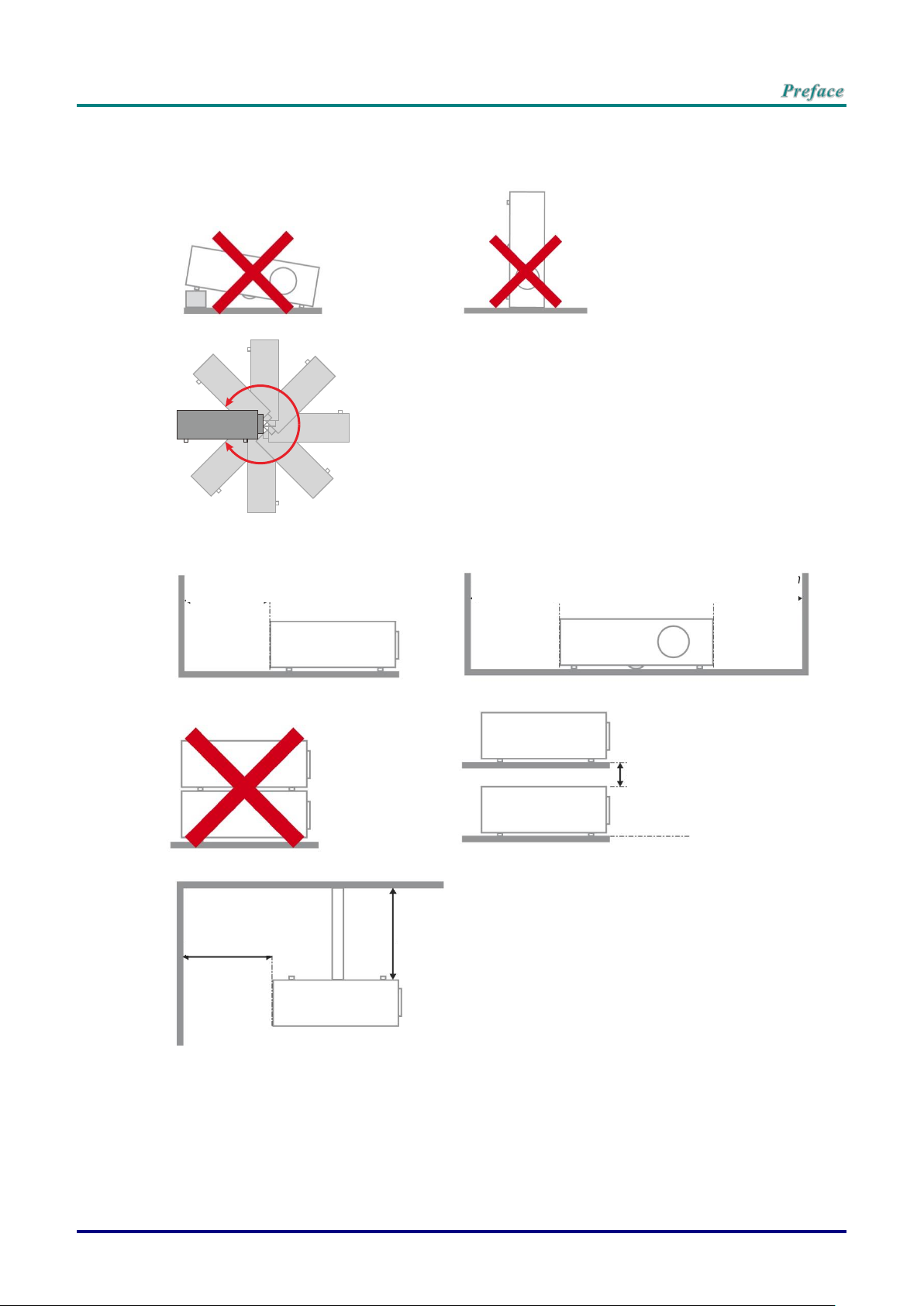
Projector Installation Notice
Do not tilt the projector to the left or right, otherwise lamp life could decrease dramatically, and
may lead to other unpredictable damages.
There is no limit on the tilt angle upward or downward.
Allow at least 50 cm clearance around the exhaust vent.
Ensure that the intake vents do not recycle hot air from the exhaust vent.
When operating the projector in an enclosed space, ensure that the surrounding air temperature
within the enclosure does not exceed operation temperature while the projector is running, and the
air intake and exhaust vents are unobstructed.
All enclosures should pass a certified thermal evaluation to ensure that the projector does not
recycle exhaust air, as this may cause the device to shutdown even if the enclosure temperature is
with the acceptable operation temperature range.
– iii –
Page 5

Verify Installation Location
To supply power, the 3-blade (with earthing lead) socket should be used to ensure proper
grounding and equalized ground potential for all of the equipment in the Projector System.
The power code provided with the Projector should be used. In case of any missing item, other
qualified 3-blade (with earthing lead) power cord can be used as substitution; however, do not use
2-blade power cord.
Verify if the voltage is stable, grounded properly and there is no electricity leakage.
Measure total power consumption which should not higher the safety capacity and avoid safety
issue and short circuit.
Turn on Altitude Mode when located in high altitude areas
The projector can only be installed upright or inverted.
When installation the bracket, make sure the weight limit is not exceed and firmly secured.
Avoid installing near air conditioner duct or subwoofer.
Avoid installing at high temperature, insufficient cooling and heavy dust locations.
Keep your product away from fluorescent lamps (>1 meter) to avoid malfunction
caused by IR interference
The VGA IN connector should be connected to the VGA IN port. Note that it should be inserted
tightly, with the screws on both sides securely fastened to ensure proper connection of the signal
wire for achieving optimal display effect.
The AUDIO IN connector should be connected to the AUDIO IN port and CANNOT be connected
to AUDIO OUT or other ports like BNC, RCA; otherwise, it will lead to mute output and even
DAMAGE the port.
Install the projector above 200cm to avoid damage.
The power cord and signal cable should be connected before power on the projector. During the
projector starting and operating process, DO NOT insert or remove the signal cable or the power
cord to avoid damaging the projector.
Cooling notes
Air outlet
Make sure the air outlet is 50cm clear of any obstruction to ensure proper cooling.
Air outlet location should not be in front of the lens of other projector to avoid causing illusions.
Keep the outlet at least 100cm away from the inlets of other projectors
The projector generates a massive amount of heat during use. The internal fan dissipates the heat
of the projector when shutting down, and such process may continue for a certain period. After the
project enters STANDBY MODE status, press the AC power button to turn off the projector and
remove the power cord. DO NOT remove the power cord during the shutdown process, as it may
cause damage to the projector. In the meantime, the delayed heat radiating will also affect the
service life of the projector. The shutdown process may vary depending on the model used.
Whatever the case may be, be sure to disconnect the power cord till after the projector enters the
STANDBY status.
Air inlet
Make sure there is no object blocking air input within 30 cm.
Keep the inlet away from other heat sources
Avoided heavy dust area
— iv —
Page 6
DISPOSAL: Do not use household or municipal waste collection services for
disposal of electrical and electronic equipment. EU countries require the use
of separate recycling collection services.
Power Safety
Only use the supplied power cord.
Do not place anything on the power cord. Place the power cord where it will not be in the way of
foot traffic.
Remove the batteries from the remote control when storing or not in use for a prolonged period.
Replacing the Lamp
Replacing the lamp can be hazardous if done incorrectly. See Replacing the Projection Lamp on page 63
for clear and safe instructions for this procedure. Before replacing the lamp:
Unplug the power cord.
Allow the lamp to cool for about one hour.
Cleaning the Projector
Unplug the power cord before cleaning. See Cleaning the Projector page 66.
Allow the lamp to cool for about one hour.
Regulatory Warnings
Before installing and using the projector, read the regulatory notices in the Regulatory Compliance on
page 83.
Important Recycle Instructions:
Lamp(s) inside this product contain mercury. This product may contain other electronic waste that
can be hazardous if not disposed of properly. Recycle or dispose in accordance with local, state, or federal
Laws. For more information, contact the Electronic Industries Alliance at WWW.EIAE.ORG. For lamp
specific disposal information check WWW.LAMPRECYCLE.ORG.
Symbol Explanations
– v –
Page 7

Main Features
Lightweight unit, easy to pack away and transport.
Compatible with all major video standards including NTSC, PAL, and SECAM.
A high brightness rating allows for presentations in daylight or in lit rooms.
Flexible setup allows for front, rear projections.
Line-of-vision projections remain square, with advanced keystone correction for angled
projections.
Input source automatically detected.
High brightness for projection in just about any environment.
Supports resolutions up to WUXGA for clear and crisp images.
DLP® and BrilliantColor™ technologies from Texas Instruments.
Centered lens for easy installation.
Horizontal and vertical lens shift.
MHL device compatibility for streaming of video and audio content from a compatible mo-
bile device.
Built-in speaker with multiple audio-in and audio-out ports.
Network ready for integration and system administration via RJ45.
Sealed engine to minimizing the impact of dust and smoke.
Top sided lamp cover for simple lamp removal and insertion.
Anti-theft security features include: Kensington security slot, security bar.
About this Manual
This manual is intended for end users and describes how to install and operate the DLP projector. Wherever possible, relevant information—such as an illustration and its description—has been kept on one
page. This printer-friendly format is both for your convenience and to help save paper, thereby protecting
the environment. It is suggested that you only print sections that are relevant to your needs.
— vi —
Page 8

Table of Contents
GETTING STARTED ........................................................................................................................................................... 1
PACKING CHECKLIST ........................................................................................................................................................... 1
VIEWS OF PROJECTOR PARTS ............................................................................................................................................... 2
Front-right View ............................................................................................................................................................ 2
Top view—On-Screen Display (OSD) buttons and LEDs ...................................................................................... 3
Rear view ....................................................................................................................................................................... 4
Bottom view ................................................................................................................................................................... 6
REMOTE CONTROL PARTS ................................................................................................................................................... 7
REMOTE CONTROL OPERATING RANGE ............................................................................................................................. 10
PROJECTOR AND REMOTE CONTROL BUTTONS .................................................................................................................. 10
SETUP AND OPERATION ............................................................................................................................................... 11
INSERTING THE REMOTE CONTROL BATTERIES ................................................................................................................. 11
STARTING AND SHUTTING DOWN THE PROJECTOR ............................................................................................................. 12
ADJUSTING THE PROJECTOR LEVEL ................................................................................................................................... 14
ADJUSTING PROJECTED IMAGE POSITION USING LENS SHIFT ............................................................................................ 15
Adjusting the vertical image position ....................................................................................................................... 16
Adjusting the horizontal image position .................................................................................................................. 17
ADJUSTING THE ZOOM, FOCUS AND KEYSTONE ................................................................................................................ 18
ADJUSTING THE VOLUME .................................................................................................................................................. 19
ON-SCREEN DISPLAY (OSD) MENU SETTINGS ...................................................................................................... 20
OSD MENU CONTROLS ..................................................................................................................................................... 20
Navigating the OSD ................................................................................................................................................... 20
SETTING THE OSD LANGUAGE .......................................................................................................................................... 21
OSD MENU OVERVIEW ..................................................................................................................................................... 22
PICTURE >> BASIC MENU ............................................................................................................................................... 26
PICTURE >> ADVANCED MENU ...................................................................................................................................... 27
HSG Adjustment ......................................................................................................................................................... 28
User Color Temp ........................................................................................................................................................ 28
White Balance ............................................................................................................................................................. 29
DISPLAY MENU ............................................................................................................................................................... 30
4 Corner ....................................................................................................................................................................... 31
Pincushion ................................................................................................................................................................... 32
PC Detail Adjustment ................................................................................................................................................. 33
3D Setting .................................................................................................................................................................... 34
SYSTEM SETUP >> BASIC MENU ................................................................................................................................... 35
Presentation Timer ..................................................................................................................................................... 36
Menu Settings ............................................................................................................................................................. 36
SYSTEM SETUP >> ADVANCED MENU .......................................................................................................................... 37
Audio Settings ............................................................................................................................................................. 38
Lamp Settings ............................................................................................................................................................. 38
Closed Caption ........................................................................................................................................................... 39
Network Settings ........................................................................................................................................................ 39
BROWSER BASED MANAGEMENT ...................................................................................................................................... 44
PWPRESENTER ................................................................................................................................................................... 47
Using the Broadcasting Function ............................................................................................................................. 53
Remote Desktop Control through pwPresenter ..................................................................................................... 55
Presenting From a USB Reader .............................................................................................................................. 57
RS232 BY TELNET FUNCTION ............................................................................................................................................ 59
Quick Start-Guide for TELNET ................................................................................................................................. 59
INFORMATION MENU .................................................................................................................................................... 62
MAINTENANCE AND SECURITY .................................................................................................................................. 63
REPLACING THE PROJECTION LAMP ................................................................................................................................... 63
CLEANING THE PROJECTOR................................................................................................................................................ 66
Cleaning the Lens ...................................................................................................................................................... 66
Cleaning the Case ...................................................................................................................................................... 66
– vii –
Page 9

Cleaning the Air Filter ................................................................................................................................................ 67
USING THE PHYSICAL LOCK .............................................................................................................................................. 70
Using the Kensington Security Slot ......................................................................................................................... 70
Using the Security Bar Lock ..................................................................................................................................... 70
TROUBLESHOOTING ...................................................................................................................................................... 71
COMMON PROBLEMS AND SOLUTIONS ............................................................................................................................... 71
TIPS FOR TROUBLESHOOTING ............................................................................................................................................ 71
LED ERROR MESSAGES ..................................................................................................................................................... 72
IMAGE PROBLEMS .............................................................................................................................................................. 73
LAMP PROBLEMS ............................................................................................................................................................... 73
REMOTE CONTROL PROBLEMS .......................................................................................................................................... 74
AUDIO PROBLEMS ............................................................................................................................................................. 74
HAVING THE PROJECTOR SERVICED .................................................................................................................................. 74
HDMI Q & A .................................................................................................................................................................... 75
SPECIFICATIONS ............................................................................................................................................................. 76
SPECIFICATIONS ................................................................................................................................................................. 76
PROJECTION DISTANCE VS. PROJECTION SIZE .................................................................................................................... 78
Projection Distance and Size Table ......................................................................................................................... 78
TIMING MODE TABLE ........................................................................................................................................................ 79
PROJECTOR DIMENSIONS ................................................................................................................................................... 82
REGULATORY COMPLIANCE ....................................................................................................................................... 83
FCC WARNING .................................................................................................................................................................. 83
CANADA ............................................................................................................................................................................ 83
SAFETY CERTIFICATIONS ................................................................................................................................................... 83
APPENDIX I ........................................................................................................................................................................ 84
RS232 PIN ASSIGNMENTS (PROJECTOR SIDE) .................................................................................................................... 84
RS-232C PROTOCOL.......................................................................................................................................................... 84
— viii —
Page 10

Projector
Remote Control
(Batteries Included)
VGA Cable
Power Cord
CD-ROM
(This User's Manual)
Warranty Card
Quick Start Card
Packing Checklist
Carefully unpack the projector and check that the following items are included:
GETTING STARTED
Contact your dealer immediately if any items are missing, appear damaged, or if the unit does not work. It is
recommend that you keep the original packing material should you ever need to return the equipment for
warranty service.
Caution:
Avoid using the projector in dusty environments.
— 1 —
Page 11
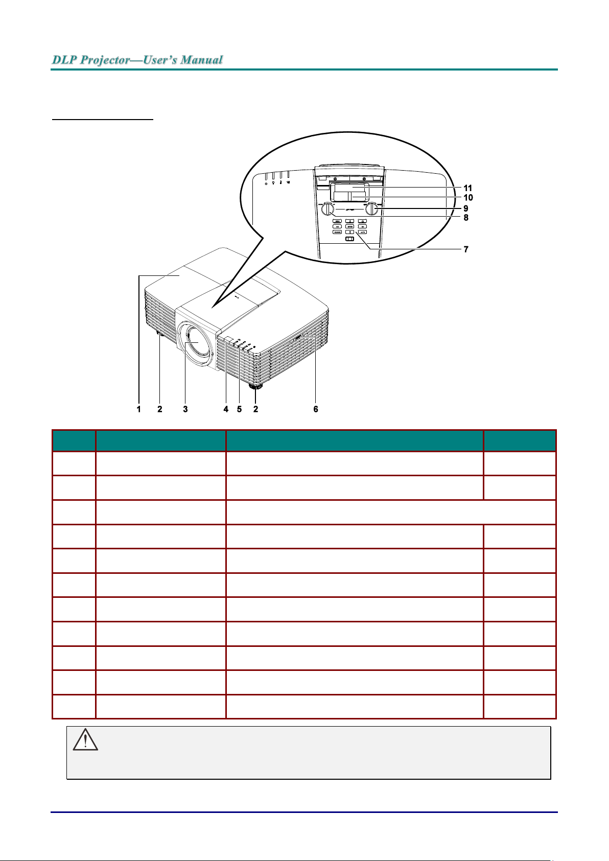
Views of Projector Parts
ITEM
LABEL
DESCRIPTION
SEE PAGE:
1.
Lamp Cover
Remove cover to replace lamp.
63
2.
Tilt Adjuster
Rotate adjuster lever to adjust angle position.
14
3.
Lens
Projection Lens.
4.
IR Receiver
Receives IR signal from remote control.
7
5.
LEDs
Displays the projector status.
3
6.
Vent
Cool air intake.
67
7.
Function Keys
On-Screen Display (OSD) buttons.
3
8.
Vertical Lens Shift
Adjusts the image position vertically.
16
9.
Horizontal Lens Shift
Adjusts the image position horizontally.
17
10.
Zoom Ring
Enlarges the projected image.
18
11.
Focus Ring
Focuses the projected image.
18
Front-right View
Important:
Ventilation openings on the projector allow for good air circulation, which keeps the projector lamp
cool. Do not obstruct any of the ventilation openings.
— 2 —
Page 12
ITEM
LABEL
DESCRIPTION
SEE PAGE:
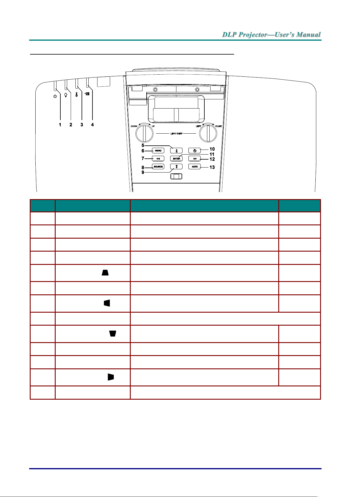
1.
Power LED
Display the power on/off sequence status.
72
2.
Lamp LED
Display the lamp status.
72
3.
Temp LED
Display the thermal status.
72
4.
Filter LED
Display the filter replacing warning message.
72
5.
▲ (Up Cursor) /
Navigates and changes settings in the OSD.
Quick Menu – For Vertical Keystone.
20
6.
MENU
Opens and exits OSD menus.
20
7.
◄ (Left Cursor) /
Navigates and changes settings in the OSD.
Quick Menu – For Horizontal Keystone.
20
8.
SOURCE
Enter the Source menu.
9.
▼ (Down Cursor) /
Navigates and changes settings in the OSD.
Quick Menu – For Vertical Keystone.
20
10.
Power
Turn the projector on or off.
12
11.
ENTER
Enter or confirm highlighted OSD menu item.
20
12.
► (Right Cursor) /
Navigates and changes settings in the OSD.
Quick Menu – For Horizontal Keystone.
20
13.
AUTO
Optimizes image size, position, and resolution.
Top view—On-Screen Display (OSD) buttons and LEDs
– 3 –
Page 13
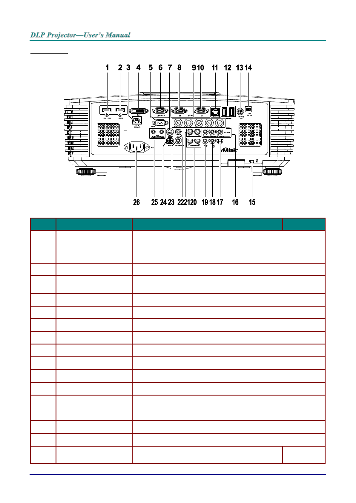
Rear view
ITEM
LABEL
DESCRIPTION
SEE PAGE:
1.
HDMI 1 /MHL
Connect the HDMI/MHL cable from an HDMI/MHL device.
Note: Set the Source to HDMI 1/MHL also can be charging connected
MHL compatible smart device as long as the projector Power
On.
2.
HDMI 2
Connect the HDMI cable from an HDMI device.
3.
RJ45 (HDBaseT)
(Available in DW3321)
Connect an RJ45 Cat5e/Cat6 cable for HDBaseT signal received.
4.
DVI-D
Connect the DVI CABLE to a display.
5.
RS-232
Connects RS-232 serial port cable for remote control.
6.
VGA OUT
Connect an RGB cable to a display (Pass through by VGA1 only).
7.
S-VIDEO
Connect a S-VIDEO cable from a video device.
8.
VGA 1
Connect an RGB cable from a computer or a video enabled device.
9.
BNC
Connect a BNC cable from a computer.
10.
VGA 2
Connect an RGB cable from a computer or a video enabled device.
11.
RJ45 (LAN)
Connect a LAN cable from Ethernet.
12.
USB
Connect a USB cable for USB host.
Note: Support 5V/1.0A for each port output as long as the projector
Power On.
13.
3D-SYNC OUT
Connect 3D IR glasses receiver unit.
14.
USB DISPLAY
Connect your projector to a PC through a USB cable.
15.
Kensington Security Slot
Secures to permanent object with a Kensington Lock
system.
70
— 4 —
Page 14
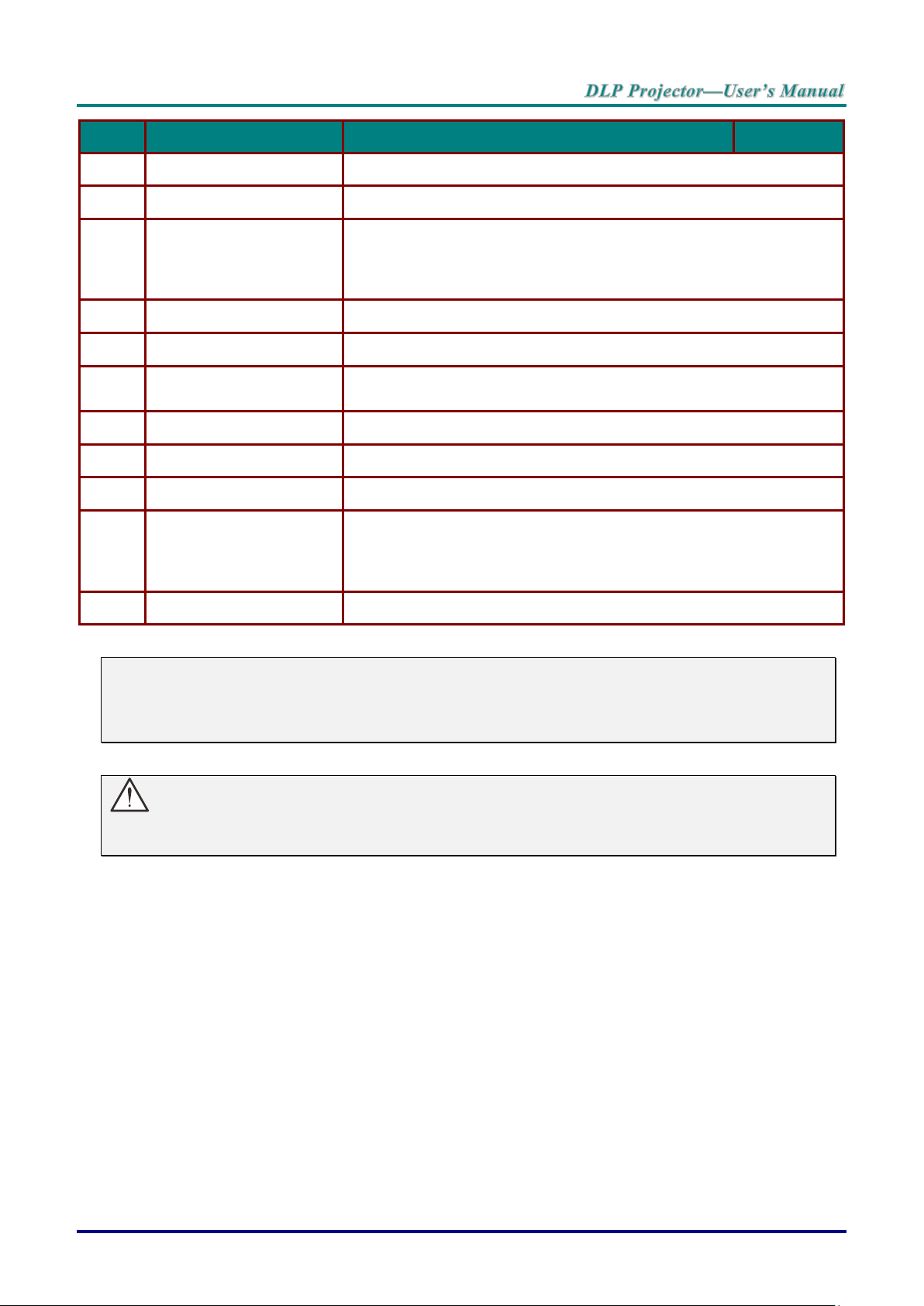
ITEM
LABEL
DESCRIPTION
SEE PAGE:
16.
AUDIO IN
Connect an AUDIO cable from the input device.
17.
IR
Receive IR signal from remote control.
18.
12V OUT
When connected to the screen through a commercially available
cable, the screen deploys automatically on start up of the projector.
The screen retracts when the projector is powered off (see notes
below).
19.
AUDIO OUT
Connect an AUDIO cable for audio loop through.
20.
AUDIO OUT L/R
Connect an AUDIO cable for audio loop through.
21.
AUDIO IN L/R
Connect the audio cables from an audio device for VIDEO or SVIDEO audio input.
22.
VIDEO
Connect the composite cable from a video device.
23.
MICROPHONE
Connect the microphone input device.
24.
SERVICE
For service personnel only.
25.
WIRE REMOTE
Connect the wire remote from remote control to the projector for wire
remote control.
Connect "WIRE REMOTE OUT" to another projector (same model)
"WIRE REMOTE IN" for serial control.
26.
AC IN
Connect the POWER cable.
Note:
To use this feature, you must plug in the connector before turn on/off the projector.
Screen controllers are supplied and supported by screen manufacturers.
Do not use this jack for anything other than intended use.
Warning:
As a safety precaution, disconnect all power to the projector and connecting devices before making
connections.
– 5 –
Page 15
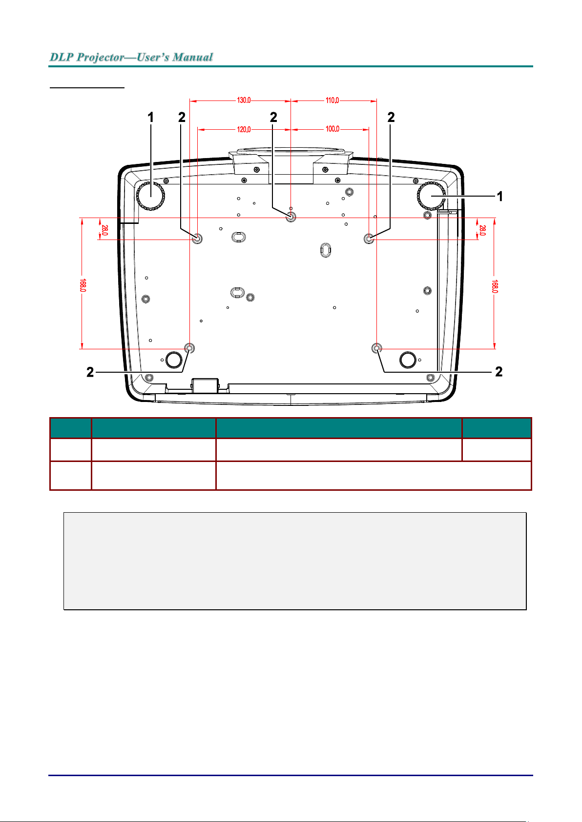
Bottom view
ITEM
LABEL
DESCRIPTION
SEE PAGE:
1.
Tilt Adjustor
Rotate adjuster lever to adjust angle position.
14
2.
Ceiling Mount Holes
Contact your dealer for information on mounting the projector on a
ceiling.
Note:
When installing, ensure that you use only UL Listed ceiling mounts.
For ceiling installations, use approved mounting hardware and M4 screws with a maximum screw
depth of 6 mm (0.23 inch).
The construction of the ceiling mount must be of a suitable shape and strength. The ceiling mount
load capacity must exceed the weight of the installed equipment, and as an additional precaution
be capable of withstanding three times the weight of the equipment (not less than 5.15 kg) over a
period of 60 seconds.
— 6 —
Page 16
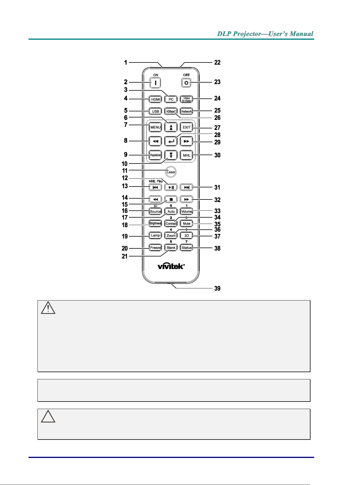
Remote Control Parts
!
Important:
1. Avoid using the projector with bright fluorescent lighting turned on. Certain high-frequency fluo-
rescent lights can disrupt remote control operation.
2. Be sure nothing obstructs the path between the remote control and the projector. If the path between the remote control and the projector is obstructed, you can bounce the signal off certain
reflective surfaces such as projector screens.
3. The buttons and keys on the projector have the same functions as the corresponding buttons on
the remote control. This user’s manual describes the functions based on the remote control.
Note:
Complies with FDA performance standards for laser products except for deviations pursuant to
Laser Notice No. 50, dated June 24, 2007
Caution:
Use of controls, adjustments or performance of procedures other than those specified herein
may result in hazardous laser light exposure.
– 7 –
Page 17
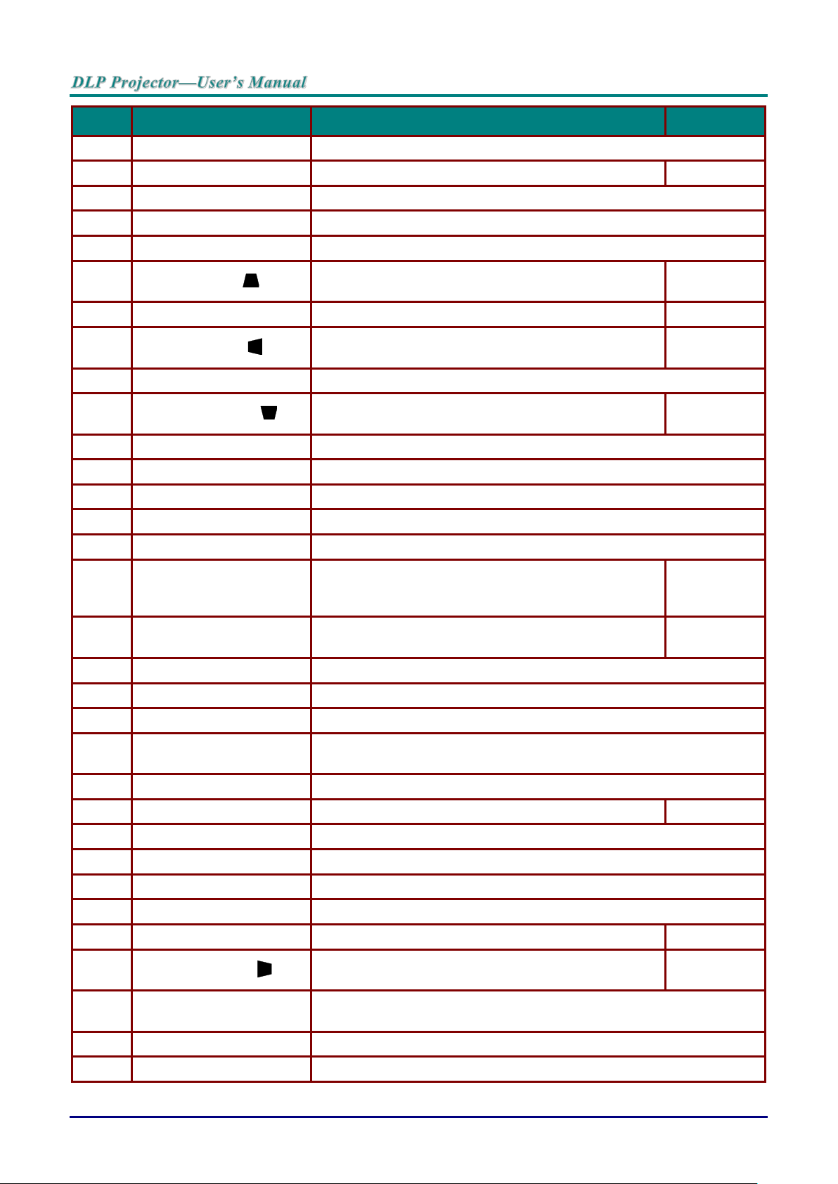
ITEM
LABEL
DESCRIPTION
SEE PAGE:
1.
IR Transmitter
Transmits signals to projector.
2.
Power On
Turns the projector on.
12
3.
PC
Displays the VGA1/VGA2/PC source selection (toggle).
4.
HDMI
Displays the HDMI1/HDMI 2/DVI source selection (toggle).
5.
USB
Displays the USB source selection.
6.
▲ (Up Cursor) /
Navigates and changes settings in the OSD.
Quick Menu – For Vertical Keystone.
20
7.
MENU
Opens the OSD.
20
8.
◄ (Left Cursor) /
Navigates and changes settings in the OSD.
Quick Menu – For Horizontal Keystone.
20
9.
Keystone
Opens the Keystone menu.
10.
▼ (Down Cursor) /
Navigates and changes settings in the OSD.
Quick Menu – For Vertical Keystone.
20
11.
Laser
Press to operate the on-screen pointer. DO NOT POINT IN EYES.
12.
Play/Pause
Play or pause video/music for MHL.
13.
Reverse
Reverse in set increments for MHL.
14.
Prev
Play the previous item on the programming list for MHL.
15.
Stop
Stop video/music playing for MHL.
16.
Source/ID
Alternate input source.
Combo key function for Remote Control customer
code settings (ID + Number).
20
17.
Auto/0
Auto adjustment for frequency, phase, and position.
Number for Remote ID setting used.
20
18.
Brightness
Displays the brightness setting bar.
19.
Lamp
Displays the lamp selections.
20.
Freeze
Freezes/unfreezes the on-screen picture.
21.
Blank/6
Makes the screen blank.
Number for Remote ID setting used.
22.
Laser
Use as on-screen pointer. DO NOT POINT IN EYES.
23.
Power Off
Turns the projector off.
12
24.
Video/S-Video
Displays the VIDEO/S-VIDEO source selection.
25.
Network
Displays the Network source selection.
26.
HDBaseT
Displays the HDBaseT source selection.
27.
EXIT
Return to last OSD page.
28.
ENTER
Enters and confirms settings in the OSD.
20
29.
► (Right Cursor) /
Navigates and changes settings in the OSD.
Quick Menu – For Horizontal Keystone.
20
30.
MHL
Enable the Mobile High-Definition Link technology feature for smart
devices.
31.
Forward
Forward in set increments for MHL.
32.
Next
Play the following item on the programming list for MHL.
— 8 —
Page 18
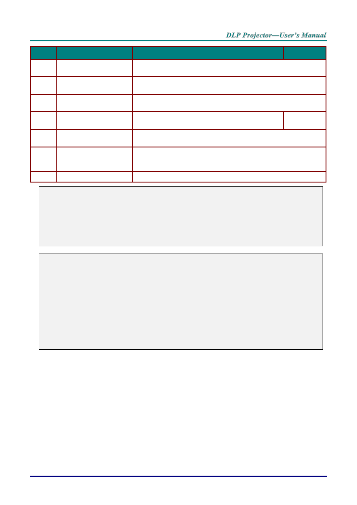
ITEM
LABEL
DESCRIPTION
SEE PAGE:
33.
Volume/1
Displays the Volume setting bar.
Number for Remote ID setting used.
34.
Contrast/2
Displays the Contrast settings bar.
Number for Remote ID setting used.
35.
Mute/3
Mutes the built-in speaker.
Number for Remote ID setting used.
36.
Zoom/4
Displays the digital zoom settings bar.
Number for Remote ID setting used.
18
37.
3D/5
Enable 3D feature.
Number for Remote ID setting used.
38.
Status/7
Opens the OSD Status menu (the menu only opens when an input
device is detected).
Number for Remote ID setting used.
39.
Wired Jack
Connect wire remote to the projector.
Note:
Remote Combo Key Settings:
ID+0: Reset Remote Control customer code to default settings.
ID+1: Set Remote Control customer code to "1".
~
ID+7: Set Remote Control customer code to "7".
Projector also need setting ID for unique control. Projector ID settings see page 37.
Note:
When the projector is under MHL mode, The keypad on projector should be with the same definition of the key on remote control.
When MHL function:
MENU for App settings, ▲ Up, ▼ Down, ◄ Left and ► Right are used as directional arrows, also
included ENTER and EXIT.
Controlling your smart device with the remote control:
When the projector projects the contents from your MHL compatible smart device, you can use the
remote control to control your smart device.
To enter the MHL mode, the following buttons are available for controlling your smart device, Arrow
keys (▲ Up, ▼ Down, ◄ Left, ► Right), MENU, EXIT, MHL control buttons.
– 9 –
Page 19

Remote Control Operating Range
The remote control uses infrared transmission to control the projector. It is not necessary to point the
remote directly at the projector. Provided you are not holding the remote perpendicular to the sides or the
rear of the projector, the remote will function well within a radius of about 7 meters (23 feet) and 15
degrees above or below the projector level. If the projector does not respond to the remote control, move a
little closer.
Projector and Remote Control Buttons
The projector can be operated using the remote control or the buttons on the top of the projector. All
operations can be carried out with the remote control; however, the buttons on the projector are limited in
use.
— 10 —
Page 20
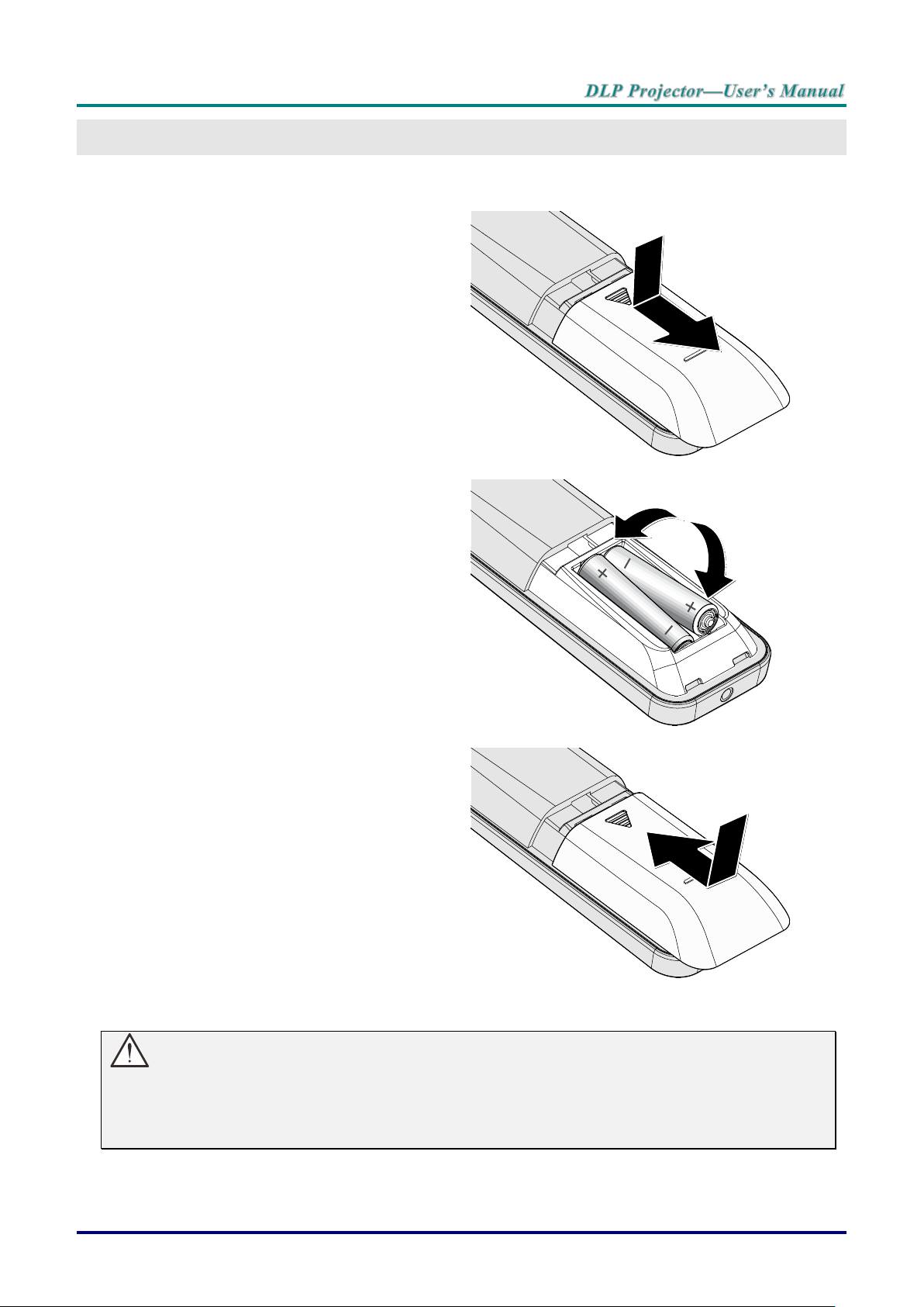
Inserting the Remote Control Batteries
1.
Remove the battery compartment
cover by sliding the cover in the direction of the arrow.
2.
Insert the battery with the positive
side facing up.
3.
Replace the cover.
SETUP AND OPERATION
Caution:
1. Only use AAA batteries (Alkaline batteries are recommended).
2. Dispose of used batteries according to local ordinance regulations.
3. Remove the batteries when not using the projector for prolonged periods.
– 11 –
Page 21
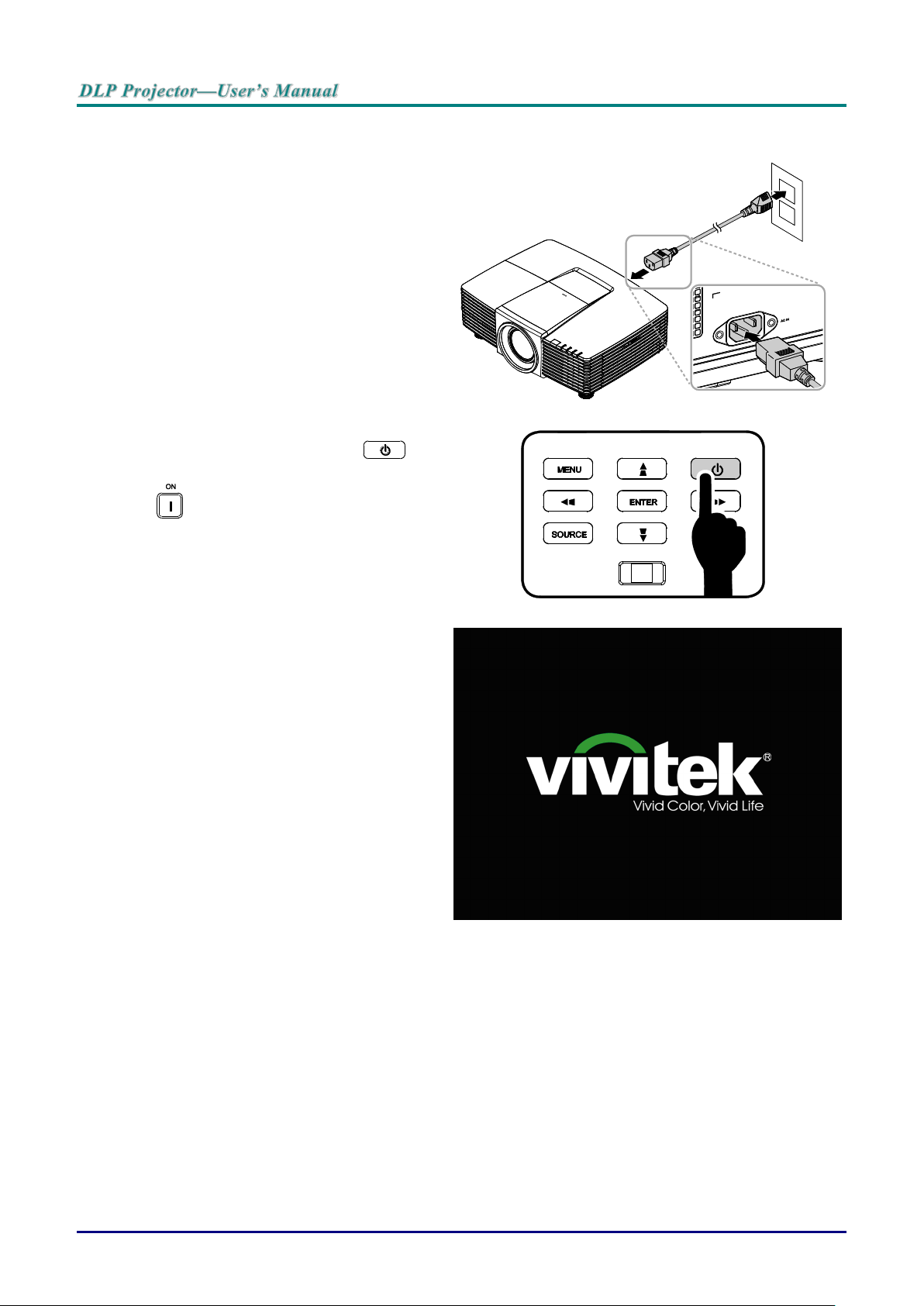
Starting and Shutting down the Projector
1.
Securely connect the power cord and
signal cable. When connected, the power
led will flash green to solid green.
2.
Turn on the lamp by pressing “ ”
button on the top of the projector or
“ ” on the remote control.
The PWR LED will now flash green.
The startup screen will display in
approximately 30 seconds. The first time
you use the projector, you can select
your preferred language from quick menu
after the startup screen display. (See
Setting the OSD Language on page 21)
— 12 —
Page 22
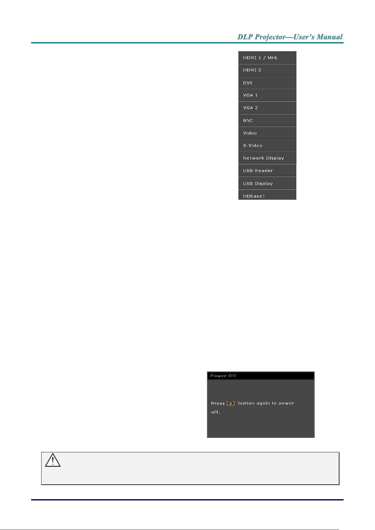
3.
If more than one input device is
connected, press the SOURCE button
and use ▲▼ to scroll among devices.
(Component is supported through the
RGB to Component adapter.)
HDMI 1 / MHL: High-Definition Multimedia Interface
and Mobile High-Definition Link
compatible
HDMI 2: High-Definition Multimedia Interface
compatible
DVI: DVI
VGA 1 / 2: Analog RGB
DVD input YCbCr/ YPbPr, or HDTV input
YPbPr via D-sub connector
BNC: Analog RGB
VIDEO: Tradition composite video
S-Video: Super video (Y/C separated)
Network Display: Network Display Source
USB Reader: USB reader Source
USB Display: USB Display from PC USB connection
HDBaseT: Digital Video trough the HDBaseT
transmitter (Available in DH3321)
Note: Using a single HDBaseT CAT5e cable, the
projector supports an HDBaseT connection distances to
100m/328ft.
4.
When the “Power Off? /Press Power
again” message appears, press the
POWER button. The projector turns off.
Caution:
Do not unplug the power cord until the POWER LED stops flashing – indicating the projector has
cooled down.
– 13 –
Page 23
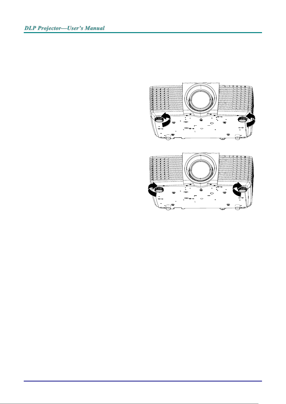
Adjusting the Projector Level
1.
To raise the level of the projector, twist
the adjusters counter clockwise.
2.
To lower the level of the projector, lift the
projector and twist the adjusters
clockwise.
Take note of the following when setting up the projector:
The projector table or stand should be level and sturdy.
Position the projector so that it is perpendicular to the screen.
Ensure the cables are in a safe location. You could trip over them.
— 14 —
Page 24
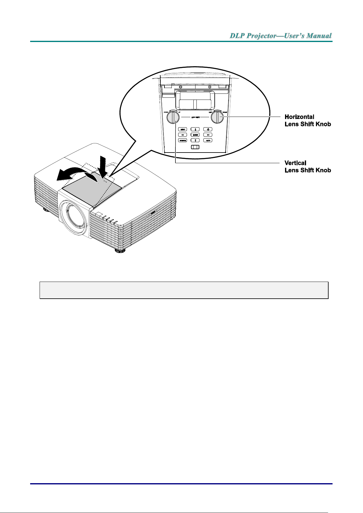
Adjusting Projected Image Position Using Lens Shift
The Lens Shift feature provides a lens shift function that can be used to adjust the position of the projected
image either horizontally or vertically within the range detailed below.
Note:
Do not rotate lens shift knob further under click sound and lightly press the knob to rotate back.
– 15 –
Page 25
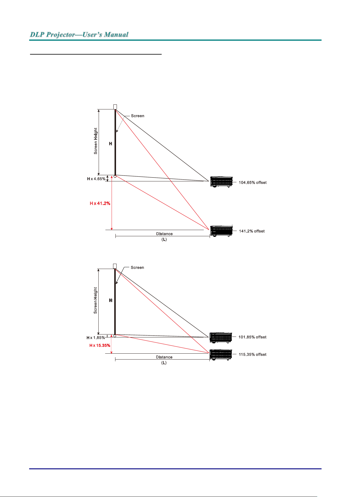
Adjusting the vertical image position
The vertical image height can be adjusted between 141.2% and 104.65% for WXGA, 115.35% and
101.85% for XGA of image height. Note that the maximum vertical image height adjustment can be limited
by the horizontal image position. For example it is not possible to achieve the maximum vertical image
position height detailed above if the horizontal image position is at maximum.
WXGA
XGA
— 16 —
Page 26
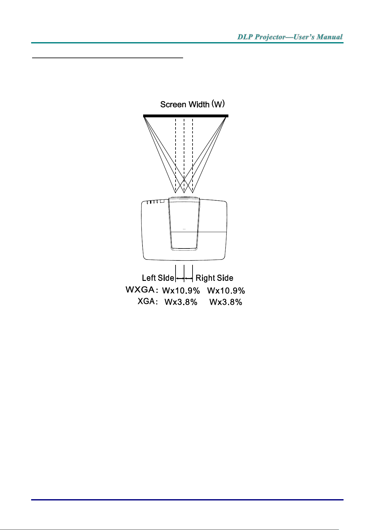
Adjusting the horizontal image position
With the lens in the center position the horizontal image position can be adjusted to the left or right by up
to a maximum of 10.9% for WXGA, 3.8% for XGA of the image width. Note that the maximum horizontal
image height adjustment can be limited by the vertical image position. For example it is not possible to
achieve the maximum horizontal image position if the vertical image position is at maximum.
– 17 –
Page 27
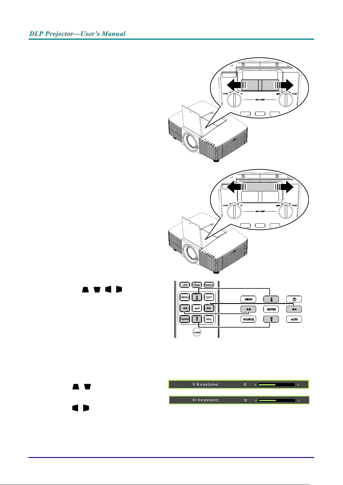
Adjusting the Zoom, Focus and Keystone
1.
Use the Image-zoom control (on the
projector only) to resize the projected
image and screen size.
2.
Use the Image-focus control (on the
projector only) to sharpen the projected
image.
3.
Press the / / / buttons (on the
projector or the remote control) to correct
vertical or horizontal image-trapezoid or
press the Keystone button (on the
remote) to selected V (Vertical) or H
(Horizontal) keystone.
Remote control and OSD panel
4.
The keystone control appears on the
display.
Press / for V Keystone correcting
image.
Press / for H Keystone correcting
image.
— 18 —
Page 28
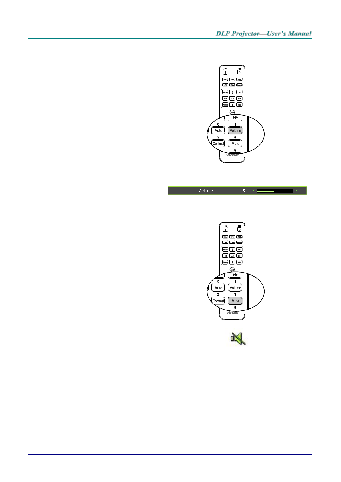
Adjusting the Volume
1.
Press the Volume buttons on the remote
control.
The volume control appears on the
display.
2.
Press the ◄ / ► buttons on the keypad
to adjust Volume +/-.
3.
Press the MUTE button to turn off the
volume (This feature is available only on
the remote).
– 19 –
Page 29
ON-SCREEN DISPLAY (OSD) MENU SETTINGS
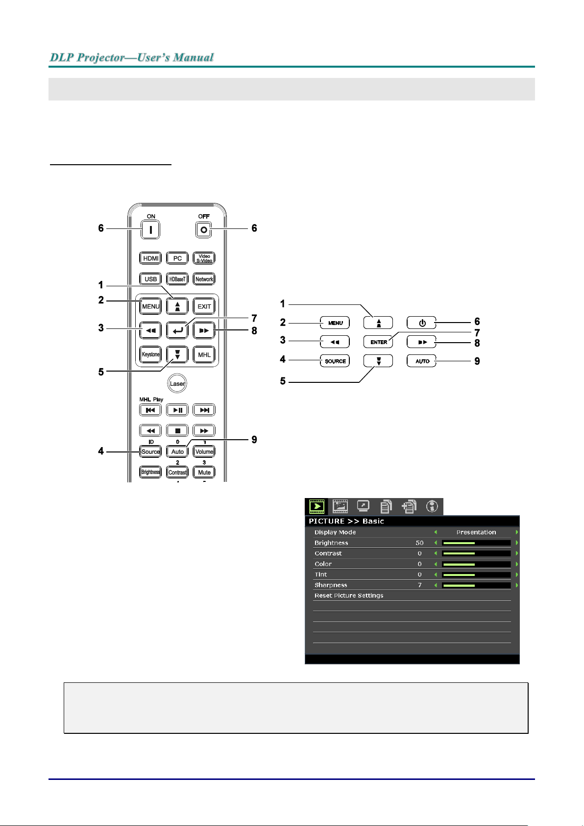
1. To enter the OSD, press the MENU button.
2. There are six menus. Press the cursor ◄ / ►
buttons to move through the menus.
3. Press the cursor / ▼ buttons to move up
and down in a menu.
4. Press the cursor ◄ / ► buttons to change
values for settings.
5. Press the MENU button to close the OSD or
leave a submenu. Press the EXIT button to
return to the previous menu.
OSD Menu Controls
The projector has an OSD that lets you make image adjustments and change various settings.
Navigating the OSD
You can use the remote control cursor buttons or the buttons on the top of the projector to navigate and
make changes to the OSD. The following illustration shows the corresponding buttons on the projector.
Note:
Depending on the video source, not all items in the OSD are available. For example, the Horizontal/Vertical Position items in the PC Detail Adjustment menu can only be modified when
connected to a PC. Items that are not available cannot be accessed and are grayed out.
— 20 —
Page 30
Setting the OSD Language
Set the OSD language to your preference before continuing.
1. Press the MENU button. Press the cursor ◄ / ► buttons to navigate to SYSTEM SETUP >>
Basic.
2. Press the cursor ▲ / ▼ buttons until Language is highlighted.
3. Press the cursor ◄ / ► buttons until the language you want is selected.
4. Press the MENU button to close the OSD.
– 21 –
Page 31

OSD Menu Overview
MAIN MENU
SUB MENU
SETTINGS
PICTURE >>
Basic
Display Mode
Presentation, Bright, Game,
Movie, Vivi, TV, sRGB,
Blackboard, DICOM SIM, 3D,
User1, User2
Brightness
0~100
Contrast
50~50
Color
50~50
Tint
50~50
Sharpness
0~15
Reset Picture
Settings
Current
All
Cancel
PICTURE >>
Advanced
Brilliant Color
On, Off
Color
Temperature
D65 (Warm), D75 (Normal),
D83 (Cool)
Wall Color
Off, Light Yellow, Pink, Light
Green, Blue, Blackboard
Gamma
1.8, 2.0, 2.2, 2.4, B&W, Linear,
S-curve
HSG Adjustment
Primary Color
R, G, B, C, M, Y
Hue
-99~99
Saturation
0~199
Gain
5~195
User Color Temp
White Gain Red
0~100
White Gain Green
0~100
White Gain Blue
0~100
White Balance
Red Gain
0~100
Green Gain
0~100
Blue Gain
0~100
Red Offset
-50~50
Green Offset
-50~50
Blue Offset
-50~50
Use the following illustration to quickly find a setting or determine the range for a setting.
— 22 —
Page 32

MAIN MENU
SUB MENU
SETTINGS
DISPLAY
Aspect Ratio
Fill, 4:3, 16:9, 16:10, Letter,
Box, Native, 2.35:1
V Keystone
-30 ~30
H Keystone
-25 ~25
4 Corner
Left-Top, Right-Top, RightBottom, Left-Bottom
Pincushion
Horz. Left, Horz. L+R, Horz.
Right, Vert. Top, Vert. T+B,
Vert. Bottom
PC Detail
Adjustment
Auto
Frequency
-15 ~ 15
Phase
0~63
Horizontal
Position
-5 ~ 5
Vertical Position
-5 ~ 5
3D Setting
3D Mode
Auto, Top/Bottom, Frame
Sequential, Frame Packing,
Side By Side, Off
3D Sync
Off, DLP-Link, IR
3D Sync Invert
Off, On
Digital Zoom
0 ~10
Video/YUV signal only 0~8
SYSTEM
SETUP >>
Basic
Presentation
Timer
Timer Period
1~240
Timer
Off, On
Language
English, 한국어, Hrvatski,
Français, Svenska, Română,
Deutsch, Nederlands, Norsk,
Italiano, Türkçe, Dansk,
Español, Čeština, Български,
Русский, Português, Suomi, 繁
體中文, ไทย, Indonesian, 簡体中
文, Polski, Ελληνικά, 日本語,
Magyar, ةيبرعلا,
Projection
Front Table, Rear Table, Front
Ceiling, Rear Ceiling
Menu Settings
Menu Display
Time
5 Sec, 10 Sec, 20 Sec, 30 Sec,
Always
Menu position
Top-Left, Top-Right, Center,
Bottom-Left, Bottom-Right
Background Color
Vivitek, Black, Blue, Purple
Splash Logo
Vivitek, Black, Blue
Auto Power Off
Disable, 5 Min, 10 Min, 15 Min,
20 Min, 25 Min, 30 Min
Sleep Timer
Disable, 30 Min, 1 Hr, 2 Hr, 3
Hr, 4Hr, 8Hr, 12 Hr
Auto Search
On, Off
– 23 –
Page 33

MAIN MENU
SUB MENU
SETTINGS
SYSTEM
SETUP >>
Advanced
High Altitude
Mode
Off, On
Audio Settings
Mute
Off, On
Volume
0 ~ 10
Out
Off, Mini, RCA
Lamp Settings
Lamp Mode
Normal, ECO, Dynamic ECO
Reset Lamp Timer
Yes, No
Total Lamp Hour
Test Pattern
Off, Grid, White, Red, Green,
Blue, Black
Closed Caption
Closed Caption
Enable
Off, On
Caption Version
CC1, CC2, CC3, CC4
Low Power Mode
Off, On, On By Lan
Network Settings
Wired Lan
Status
Connect, Disconnect
DHCP
On, Off
IP Address
0~255, 0~255, 0~255, 0~255
Subnet Mask
0~255, 0~255, 0~255, 0~255
Default Gateway
0~255, 0~255, 0~255, 0~255
DNS Server
0~255, 0~255, 0~255, 0~255
Apply
Wireless Lan
Status
Connect, Disconnect
SSID
Refresh, Other
SSID Display
On, Off
IP Address
0~255, 0~255, 0~255, 0~255
Connection Mode
AP, Infrastructure
Apply
Remote Desktop
Account
Password
Connection Mode
AP, Infrastructure
Projection Login
Code
On, Off
Broadcasting
Broadcasting
On, Off
Channel
2~25
IP Address
AMX Device
Discovery
On, Off
MAC Address
xx.xx.xx.xx.xx.xx
Reset All Settings
Reset, Cancel
Air Filter Timer
Reset
Yes, No
Remote ID
Default, 1, 2, 3, 4, 5, 6, 7
— 24 —
Page 34

MAIN MENU
SUB MENU
SETTINGS
INFORMATION
Source
Picture Mode
Lamp Mode
Resolution
3D Info
Lamp Hour
(Normal, ECO,
Total)
Air filter hour
Firmware Version
Remote ID
S/N
– 25 –
Page 35

PICTURE >> Basic Menu
ITEM
DESCRIPTION
Display Mode
Press the cursor ◄ / ► buttons to set the display mode.
Note: The DISCOM SIM mode simulates the grayscale/gamma performance of the
equipment used for "Digital Image and Communication in Medicine"(DICOM).
Important: This display mode should NEVER be used for medical diagnosis; it is
for education/training purpose only.
Brightness
Press the cursor ◄ / ► buttons to adjust the display brightness.
Contrast
Press the cursor ◄ / ► buttons to adjust the display contrast.
Color
Press the cursor ◄ / ► buttons to adjust the video saturation.
Note: This function is only available when Component, Video or S-Video input
source is selected.
Tint
Press the cursor ◄ / ► buttons to adjust the video tint/hue.
Note: This function is only available when Component, Video or S-Video with
NTSC system input source is selected.
Sharpness
Press the cursor ◄ / ► buttons to adjust the display sharpness.
Note: This function is only available when Component, Video or S-Video input
source is selected.
Reset Picture Settings
Press the ENTER button to reset Current or All settings to default values.
Press the MENU button to open the OSD menu. Press the cursor ◄ / ► buttons to move to the PICTURE
>> Basic menu. Press the cursor ▲ / ▼ buttons to move up and down in the PICTURE >> Basic menu.
Press the cursor ◄ / ► buttons to change values for settings.
Note:
Customizing the settings in PICTURE >> Basic menu is only available in User 1 / 2 mode.
— 26 —
Page 36

ITEM
DESCRIPTION
Brilliant Color
Press the cursor ◄ / ► buttons to set the brilliant color.
Color Temperature
Press the cursor ◄ / ► buttons to set the color temperature.
Wall Color
Press the cursor ◄ / ► buttons to select different wall color setting.
Gamma
Press the cursor ◄ / ► buttons to adjust the gamma correction of the display.
HSG Adjustment
Press the ENTER button to enter the HSG Adjustment sub menu. See HSG
Adjustment on page 28.
User Color Temp
Press the ENTER button to enter the User Color Temp sub menu. See User Color
Temp on page 28.
White Balance
Press the ENTER button to enter the White Balance sub menu.
See White Balance on page 29.
PICTURE >> Advanced Menu
Press the MENU button to open the OSD menu. Press the cursor ◄ / ► buttons to move to the
PICTURE >> Advanced menu. Press the cursor ▲ / ▼ buttons to move up and down in the
PICTURE >> Advanced menu. Press the cursor ◄ / ► buttons to change values for settings.
– 27 –
Page 37

HSG Adjustment
ITEM
DESCRIPTION
Primary Color
Press the cursor ◄ / ► buttons to set the Primary Color.
Hue
Press the cursor ◄ / ► buttons to adjust the Hue.
Saturation
Press the cursor ◄ / ► buttons to adjust the Saturation.
Gain
Press the cursor ◄ / ► buttons to adjust the Gain.
ITEM
DESCRIPTION
White Gain Red
Press the cursor ◄ / ► buttons to adjust the White Gain Red.
White Gain Green
Press the cursor ◄ / ► buttons to adjust the White Gain Green.
White Gain Blue
Press the cursor ◄ / ► buttons to adjust the White Gain Blue.
Press the ENTER button to enter the HSG Adjustment sub menu.
User Color Temp
Press the ENTER button to enter the User Color Temp sub menu.
— 28 —
Page 38

White Balance
ITEM
DESCRIPTION
Red Gain
Press the cursor ◄ / ► buttons to adjust the Red Gain.
Green Gain
Press the cursor ◄ / ► buttons to adjust the Green Gain.
Blue Gain
Press the cursor ◄ / ► buttons to adjust the Blue Gain.
Red Offset
Press the cursor ◄ / ► buttons to adjust the Red Offset.
Green Offset
Press the cursor ◄ / ► buttons to adjust the Green Offset.
Blue Offset
Press the cursor ◄ / ► buttons to adjust the Blue Offset.
Press the ENTER button to enter the White Balance sub menu.
– 29 –
Page 39

DISPLAY Menu
ITEM
DESCRIPTION
Aspect Ratio
Press the cursor ◄ / ► buttons to set the aspect ratio.
Note: Without support when 3D mode activated.
Vertical Keystone
Press the cursor ◄ / ► buttons to adjust the vertical keystone.
Horizontal Keystone
Press the cursor ◄ / ► buttons to adjust the horizontal keystone.
Note: Without support when 3D mode activated.
4 Corner
Press the ENTER button to enter the 4 Corner sub menu. See 4 Corner on page
31.
Note: Without support when 3D mode activated.
Pincushion
Press the ENTER button to enter the Pincushion sub menu. See Pincushion on
page 32.
Note: Without support when 3D mode activated.
PC Detail Adjustment
Press the ENTER button to enter the PC Detail Adjustment sub menu. See PC
Detail Adjustment on page 33.
3D Setting
Press the ENTER button to enter the 3D Setting sub menu. See 3D Setting on
page 34.
Digital Zoom
Press the cursor ◄ / ► buttons to adjust the digital zoom.
Note:
1. Without support when 3D mode activated.
2. Resync signal will adjust digital zoom to 0 automatically.
3. Aspect ratio adjustment will make digital zoom back to 0 automatically.
4. Signal re-sync will make digital zoom back to 0.
5. Only 0~8 is allowed to adjust for Video/YUV signal.
Press the MENU button to open the OSD menu. Press the cursor ◄ / ► buttons to move to the DISPLAY
menu. Press the cursor ▲ / ▼ buttons to move up and down in the DISPLAY menu. Press the cursor
◄ / ► buttons to change values for settings.
— 30 —
Page 40

4 Corner
Press the ENTER button to enter the 4 Corner sub menu.
1. Press the cursor ▲ / ▼ / ◄ / ► buttons to select a corner and press ENTER.
2. Press the cursor ▲ / ▼ buttons to adjust vertical and press the cursor ◄ / ► buttons to
adjust horizontal.
3. Press ENTER to save the settings.
– 31 –
Page 41

Pincushion
Press the ENTER button to enter the Pincushion sub menu.
1. Press the cursor ▲ / ▼ buttons to select one or both side and press ENTER.
Note:
Only one Pincushion setting will be stored so if you want to change from the previous direction to
the other, the notice message will pop-up to remind you to reset the previous Pincushion setting.
2. Press the cursor ▲ / ▼ / ◄ / ► buttons to adjust the desired side convex or concave.
3. Press ENTER to save the settings.
— 32 —
Page 42

ITEM
DESCRIPTION
Auto
Press the ENTER/AUTO buttons on the control panel or the ENTER/AUTO buttons on
the remote control to automatically adjust frequency, phase, and position.
Frequency
Press the cursor ◄ / ► buttons to adjust the A/D sampling number.
Phase
Press the cursor ◄ / ► buttons to adjust the A/D sampling clock.
Horizontal Position
Press the cursor ◄ / ► buttons to adjust the display position right or left.
Vertical Position
Press the cursor ◄ / ► buttons to adjust the display position up or down.
PC Detail Adjustment
Press the ENTER button to enter the PC Detail Adjustment sub menu.
Note:
Customizing the settings in PC Detail Adjustment menu is only available when PC input source
(analog RGB) is selected.
Note:
Some signals may take time to display or may not be displayed correctly.
If the Auto Adjust operation cannot optimize the PC signal, try to adjust Frequency and Phase
manually.
– 33 –
Page 43

3D Setting
ITEM
DESCRIPTION
3D Mode
Press the cursor ◄ / ► buttons to select different 3D mode.
3D Sync
Press the cursor ◄ / ► buttons to select different 3D Sync.
3D Sync Invert
Press the cursor ◄ / ► buttons to enable or disable 3D Sync Invert.
Press the ENTER button to enter the 3D Setting sub menu.
— 34 —
Page 44

ITEM
DESCRIPTION
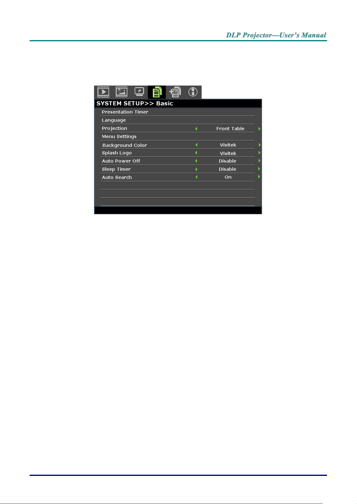
Presentation Timer
Press the ENTER button to the presentation timer menu. See Presentation Timer on
page 36.
Language
Press the cursor ◄ / ► buttons to select a different localization menu.
Projection
Press the cursor ◄ / ► buttons to choose from four projection methods.
Menu Settings
Press the ENTER button to enter the Menu Settings sub menu. See Menu Settings
on page 36.
Background Color
Press the cursor ◄ / ► buttons to select the background color when no input source is
detected.
Splash Logo
Press the cursor ◄ / ► buttons to select a different startup screen.
Auto Power Off
Press the cursor ◄ / ► buttons to set the auto power off timer. The projector
automatically turns off if no input source is detected after the preset period of time.
Sleep Timer
Press the cursor ◄ / ► buttons to set sleep timer. The projector automatically turns off
after the preset period of time.
Auto Search
Press the cursor ◄ / ► buttons to turn on or off auto search.
SYSTEM SETUP >> Basic Menu
Press the MENU button to open the OSD menu. Press the cursor ◄ / ► buttons to move to the SYSTEM
SETUP >> BASIC menu. Press the cursor ▲ / ▼ buttons to move up and down in the
SYSTEM SETUP >> BASIC menu. Press the cursor ◄ / ► buttons to change values for settings.
– 35 –
Page 45

Presentation Timer
ITEM
DESCRIPTION
Timer Period
Press the cursor ◄ / ► buttons to select timer period (1 ~ 240).
Timer
Press the cursor ◄ / ► buttons to enable or disable presentation timer.
ITEM
DESCRIPTION
Menu Display Time
Press the cursor ◄ / ► buttons to set the menu display timer before the OSD times
out.
Menu Position
Press the cursor ◄ / ► buttons to select from five OSD locations.
The Presentation Timer function can indicate the presentation time on the screen to help you achieve
better time management when giving presentations.
Menu Settings
Press the ENTER button to enter the Menu Settings sub menu.
— 36 —
Page 46

ITEM
DESCRIPTION
High Altitude Mode
Press the cursor ◄ / ► buttons to turn on or off high altitude mode.
Recommended to turn on when the altitude of the environment is higher than 1500m
(4921ft).
Audio Settings
Press the ENTER button to enter the Audio Settings sub menu.
See Audio Settings on page 38.
Lamp Settings
Press the ENTER button to enter the Lamp Settings sub menu. See Lamp Settings
on page 38.
Test Pattern
Press the cursor ◄ / ► buttons to select test pattern.
Closed Caption
Press the ENTER button to enter the Closed Caption sub menu.
See Closed Caption on page 39.
Low Power Mode
Press the cursor ◄ / ► buttons to set Low Power Mode Off, On or On by LAN.
Note: When Low Power Mode set to Off and On by LAN, VGA OUT terminal can
output signal during projector in Standby mode.
Network Settings
Press the ENTER button to enter the Network Settings sub menu.
See Network Settings on page 39.
Reset All Settings
Press the ENTER button to reset all settings to default values.
Air Filter Timer
Reset
Press the ENTER button to reset air filter timer.
Remote ID
Press the cursor ◄ / ► buttons to select remote ID to fit the current remote ID
settings.
SYSTEM SETUP >> Advanced Menu
Press the MENU button to open the OSD menu. Press the cursor ◄ / ► buttons to move to the SYSTEM
SETUP >> Advanced menu. Press the cursor ▲ / ▼ buttons to move up and down in the SYSTEM
SETUP >> Advanced menu.
– 37 –
Page 47

Audio Settings
ITEM
DESCRIPTION
Mute
Press the cursor ◄ / ► buttons to turn on or off the speaker.
Volume
Press the cursor ◄ / ► buttons to adjust the audio Volume.
Out
Press the cursor ◄ / ► buttons to select audio output connector.
Note: When select Off, the default sound is output from speakers.
ITEM
DESCRIPTION
Lamp Mode
Press the cursor ◄ / ► buttons to adjust lamp brightness.
Reset Lamp Timer
Press the ENTER button to reset the Lamp Hour after the lamp is replaced.
Total Lamp Hour
Displays the number of equivalent hours the lamp has been in use.
Note: Lamp Mode is not allowed to adjust when 3D mode is activated.
Press the ENTER button to enter the Audio Settings sub menu.
Lamp Settings
Press the ENTER button to enter the Lamp Setting sub menu.
— 38 —
Page 48

Closed Caption
ITEM
DESCRIPTION
Closed Caption
Enable
Press the cursor ◄ / ► buttons to turn on or off Closed Caption.
Caption Version
Press the cursor ◄ / ► buttons to select the Caption Version.
ITEM
DESCRIPTION
Wired LAN
Press the ENTER button to enter the Wired LAN sub menu. See Wired LAN on page
40.
Wireless LAN
Press the ENTER button to enter the Wireless LAN sub menu.
Remote Desktop
Press the ENTER button to enable remote access to the computer.
Projection Login
Code
Press the cursor ◄ / ► buttons to turn on or off the projection of the login code.
Broadcasting
Press the ENTER button to enter the Broadcasting sub menu.
AMX Device
Discovery
Press the cursor ◄ / ► buttons to turn on or off discovery of AMX devices.
MAC Address
Press the ENTER button to enter the MAC address.
Press the ENTER button to enter the Closed Caption sub menu.
Network Settings
Press the ENTER button to enter the Network Settings sub menu.
– 39 –
Page 49

Wired LAN
ITEM
DESCRIPTION
Status
Displays the network connection status.
DHCP
Press the cursor ◄ / ► buttons to turn DHCP On or Off.
Note: If you select DHCP Off, complete the IP Address, Subnet Mask, Gateway, and
DNS fields.
IP Address
Enter a valid IP address if DHCP is turned off.
Subnet Mask
Enter a valid Subnet Mask if DHCP is turned off.
Default Gateway
Displays the default Gateway address on the network.
DNS Server
Enter a valid DNS name if DHCP is turned off.
Apply
Press ENTER to confirm settings.
Press the ENTER button to enter the Wired LAN sub menu.
For simplicity and ease of operation, the projector provides diverse networking and remote management
features.
The LAN/RJ45 function of the projector through a network, such as remotely manage: Power On/Off,
Brightness and Contrast settings. Also, projector status information, such as: Video-Source, Sound-Mute,
etc.
Wired LAN Terminal Function
Remote control and monitoring of a projector from a computer through a wired LAN is possible.
Compatibility with Crestron / AMX (Device Discovery) / Extron control boxes enables projector
management through a network as well as a remote computer’s browser.
* Crestron is a registered trademark of Crestron Electronics, Inc. of the United States.
* Extron is a registered trademark of Extron Electronics, Inc. of the United States.
* AMX is a registered trademark of AMX LLC of the United States.
— 40 —
Page 50

Supported External Devices
This projector supports command inputs from a Crestron Electronics controller and related software
(RoomView ®), for further information: http://www.crestron.com/
This projector supports the AMX (Device Discovery), for further information: http://www.amx.com/
This projector complies and supports Extron device(s), for further information: http://www.extron.com/
For more information on the external devices and their related control commands supported through the
LAN/RJ45 port and the projector’s remote/control function contact the service support team directly.
LAN RJ45
1. Connect an RJ45 cable to the RJ45 port on the projector and computer.
2. On the computer, select Start >> Control Panel >> Network and Internet.
The Network and Internet screen displays.
– 41 –
Page 51

3. Click Change adapter settings to continue.
4. Right-click on Local Area Connection, and select Properties.
5. In the Properties window, select the Networking tab and select Internet Protocol (TCP/IP).
6. Click Properties.
7. Click Use the following IP address and fill in the IP address and Subnet mask.
For this example, the IP address used is as follows:
IP address: 10.10.10.99
Subnet mask: 255.255.255.0
8. Click OK to save the settings.
— 42 —
Page 52

9. On the projector (remote control) press the MENU button.
10. Select SYSTEM SETUP >> Advanced >> Network Settings >> Wired LAN. The Wired LAN
screen displays.
11. Change the IP Address and the Subnet Mask. Make sure the network settings are compatible with
those on the computer. The project and computer must be configured to use the same subnet, see
the following example.
Example:
Projector IP settings: 10.10.10. X (whereas, X is a number between 1 and 254).
Subnet Mask: 255.255.255.0
– 43 –
Page 53

Wireless LAN Settings
1. Connect the Vivitek wireless dongle (optional) to the USB TYPE-A port of the projector.
2. Select SYSTEM SETUP >> Advanced >> Network Settings >> Wireless LAN menu
3. In an AP mode connection, you must first obtain the target SSID information. In the pwPresenter
search for the wireless SSID host.
For a connection in infrastructure mode, select the projector’s SSID to connect.
4. On the computer, use the wireless network function to connect to a wireless network.
5. If the wireless network requires a password, the user must manually enter the password.
Browser Based Management
1. Open a browser such as the Microsoft Internet Explorer*.
2. In the Address bar, type the projector’s IP address as set in Wired LAN Terminal Function. The
projector is setup for web control page. The LAN/RJ45 function displays as follows.
The Information page displays the information and status of this projector.
* Adobe Flash Player 9.0 or higher is required to view the interface through the browser.
— 44 —
Page 54

The General Setup page provides the normal functionality of the OSD, such as:
power/source/volume/Freeze Auto search/Lamp mode control.
The Display Setup page provides image fine tuning functionality.
The Display Setup page provides keystone and aspect ratio adjustment functionality.
– 45 –
Page 55

The Alert and Mail Settings pages provide status and mail notification functionality.
The Network Setup page provides configuration functionality for wired or wireless network setup.
The Advance Setup page provides broadcasting and projector name modification functionality.
— 46 —
Page 56

The Presenter Setup page provides pwPresenter admin and normal user password setup.
The download page provides downloading a function for pwPresenter.
The Crestron page, supporting RoomView version 6.2.2.9, is only available on a Wired LAN network setup.
It allows remote control of the projector.
For more information, visit http://www.crestron.com.
pwPresenter
The pwPresenter is a computer-based application to allow remote display of the computer’s desktop on
the projector. pwPresenter works through a properly configured wireless or wired network connection.
Make sure all other virtual networks control programs are disabled before using pwPresenter.
– 47 –
Page 57

1. Connect an RJ45 cable to the projector and computer’s RJ45 ports.
2. Enter the IP address of the projector in the address bar of an open browser.
3. Download pwPresenter (Zipped file) from the web control page. Unzip it and install the
pwPresenter on the computer.
4. Once installed, double click the pwPresenter icon. The pw Presenter page appears.
5. Click the Search icon to search and connect to a networked display.
a. Type in the IP address (see Browser Based Management on page 44 for details.) and
click Search.
b. The networked projector is displayed. Select it to continue.
c. Click Connect and the computer’s desktop image is displayed through the projector.
— 48 —
Page 58

d. After connecting to the projector, pwPresenter prompts for a password, as set up in the
Presenter Setup screen.
e. Click the disconnect button to disconnect all available projectors.
6. Controlling the remote display
a. Click Play/Pause to display the desktop on the connected network display.
b. Display up to four computers on a single projector at one time. Click a location to display
the image. Four locations can be selected (1-4) or two in a continuous mode (Left and
right) for two computers.
c. Once the display is selected the image displays through the projector. Select any location
or revert to full screen or blank out mode.
d. Capture mode allows management of advanced functions.
e. Define the projector’s display area
i. Full Screen: displays the entire screen through the projector.
ii. FixedSize: displays a fixed screen, place the screen over a desired area to
identify the display area for the projector.
iii. Alterable: displays an adjustable screen, which is used to identify the display area
for the projector.
– 49 –
Page 59

7. Click the Basic Setting tab to configure pwPresenter basic settings.
1 2 3 4 5
a. Select the interface language: click the drop-down menu and select the desired language.
Click Apply.
b. Change the size of the FixedSize frame in capture mode. Enter the size in pixels units.
Click Apply to save the settings.
c. Enable the mirror driver upon startup (driver must be previously installed).
d. Allow message notification. Click Yes, then Apply to save the settings.
e. Displays the software information.
— 50 —
Page 60

1
2
8. Click the Advanced Setting tab to configure pwPresenter advanced settings.
a. Set the image quality setting. Click the drop-down menu to select the desired image
quality. Click Apply to save the setting.
b. Define the network port, fixed or manual. If manual is selected, enter the port number.
Click Apply to save the setting.
– 51 –
Page 61

9. Click the Global Setting tab to configure pwPresenter global settings, which allows for remote
control of the computer through the projector.
10. Click the Multicast Setting tab to configure pwPresenter broadcast settings.
— 52 —
Page 62

11. Device management.
a b c d e
f
a. Click the Display Port Location icon to adjust the location of the displayed area.
b. Click the Password icon to change the user password.
c. Click the Disconnect icon to disconnect the projector from the network.
d. Click the Webpage icon to allow access to the Vivitek webpage control interface.
e. Click the Remote Desktop icon to enable the remote access function.
f. Displays the device status and setting information. Also, provides access to conference
control mode.
Using the Broadcasting Function
The 1:N LAN Display is available in two ways.
TCP/IP—supporting up to 8 projectors (default)
Multicast—supporting up to 255 projectors (new design)
Select the channel for the corresponding IP address (grayed out): 1 to 25.
Twenty five channels (25 IPs) are available for selection, for example: 239.192.19.21 ~ 45.
Pre-set channels, such as a channel setup for emergency broadcasting, are automatically detected by the
projector and the source is displayed. Manual source selection is not required.
To activate this function:
1. Go to the SYSTEM SETUP >> Advanced >> Network Settings menu after opening the OSD menu.
2. Press ENTER.
– 53 –
Page 63

3. Press ▼ to select Broadcasting and press ◄ / ► to select On.
4. Open pwPresenter and select the Multicast Setting tab.
5. Click Search and click Apply.
6. From the Multi-cast drop-down menu select the broadcasting device (IP address).
7. Select the channel as it is setup in the projector Broadcasting menu.
8. Press Connect to broadcast the captured screen from the computer.
— 54 —
Page 64

Note:
The function requires the pwPresenter software available on the provided CD.
This function is only available when the Network Display source is selected.
Minimum system requirements: Intel® Core 2 Dou, 2.4GHz CPU, 2G DDR.
Remote Desktop Control through pwPresenter
pwPresenter provides remote desktop control function for the projector.
1. Setup a login account (User name and Password) in pwPresenter. Enter the user name in the
Name field.
2. Designate a password for read-only access in the Read-only password field.
3. Designate a password for remote control access in the Remote control password field.
Name: must be eight or more characters, capital letters (A~Z) and/or numbers (0 ~9).
Password: must be a numerical combination (1 ~ 4), a minimum of six digits.
The on-screen password is visible as left, down, right symbols.
If identical pwPresenter names are used, a duplicate error is displayed.
4. Click the tab pwPresenter >> Parameter Settings >> Global Settings to open Remote Desktop
screen.
– 55 –
Page 65

5. Select the radio button and click Yes to enable the remote control/audio capture/screen capture
function.
When you installing the pwPresenter, the operating system’s default language is selected for
pwPresenter. If a language is not available, English is selected.
a. You can select whether to allow notification message popup.
b. Once you set to activate 1:N display, 1PC/NB can display up to 8 projectors at the same
time.
c. Once set, press Apply to save the changes.
d. You can select Video or Graphic display mode.
Graphic Mode: worse image quality but faster transmission speed.
Video Mode: better image quality but slower transmission speed.
The actual transmission performance is determined by the current network bandwidth.
e. You can select whether to automatically open the pwPresenter application when the
computer is powered on.
f. Once set, press Apply to save the changes.
6. Open the OSD menu and go to the SYSTEM SETUP >> Advanced > Network Settings >
Remote Desktop.
— 56 —
Page 66

7. Enter the Account and Password the same as defined in Remote Desktop Control through
pwPresenter.
8. Select Connect and press ENTER to connect to the selected PC.
9. Connect USB keyboard or mouse to control the host PC’s desktop through the projector.
• Remote Desktop Control does not support PC Standby mode.
• Remote Desktop Control only supports LAN source so the projector source is fixed on LAN.
Presenting From a USB Reader
This feature displays a slide show of images stored on a USB flash drive connected to the projector. It can
eliminate the need for a computer source.
Image File Types
USB Reader displays images files in JPEG, GIF, TIFF, PNG and BMP formats.
• A square box on the filename identified unknown characters.
• Thai file naming system is not supported.
• GIF, TIFF, PNG and BMP formatted files can be displayed if the file is under WXGA (1280 x 800).
• If a folder contains more than 200 photos, only the first 200 photos are displayed.
Preparation
To view your pictures as a slideshow, follow these steps:
1. Connect a USB flash drive to your computer and copy files from your computer to the USB flash
drive.
2. Turn on your projector.
3. Remove the USB flash drive from your computer and plug it into the USB jack of the projector.
4. Select USB Reader from the source selection bar.
– 57 –
Page 67

USB Reader menu
ITEM
DESCRIPTION
Slideshow
Press the ENTER button to start slideshow.
Slideshow Direction
Press the cursor ◄ / ► buttons to select a slideshow direction.
Slideshow Timing
Press the cursor ◄ / ► buttons to select the image display frequency.
Repeat Slideshow
Press the cursor ◄ / ► buttons to turn on or off the repeat slideshow function.
Auto Rotation
Press the cursor ◄ / ► buttons to turn on or off auto rotate.
Best Fit
Press the cursor ◄ / ► buttons to turn on or off the best fit function, which adjusts the
image for the best screen fit.
The USB Reader menu displays only when a USB device source is selected. This menu is includes a
slideshow feature for selecting settings.
— 58 —
Page 68

RS232 by Telnet Function
The projector supports RS232 control functionality through Telnet by using a RJ45 connection.
Quick Start-Guide for TELNET
Obtain the projector’s IP-Address. Make sure the projector is properly setup to function within the local
network.
1. Disable any Windows Firewall settings to allow for Telnet access.
2. Navigate to Start > All Programs > Accessories and select Command Prompt. The command
window displays.
3. In the command window, type the IP address of the projector in the following format.
telnet ttt.xxx.yyy.zzz 23 (whereas ttt.xxx.yyy.zzz is the IP-Address of the projector.
4. Press Enter to continue.
Once the Telnet connection is established, enter commands to remotely control the project.
– 59 –
Page 69

Enabling TELNET in Windows VISTA and Windows 7
By default installation for Windows VISTA the Telnet function is not enabled. It is enabled by configuring
Windows features..
1. Navigate to Start > Control Panel in Windows Vista.
2. Select Programs to continue.
3. Select Turn Windows features on or off to open the Windows Features window.
4. Scroll down until the Telnet Client feature is displayed.
— 60 —
Page 70

5. Click the radio box to enable the Telnet Client feature.
6. Click OK to continue.
The feature requires additional Windows configuration.
RS232 Spec sheet for Telnet
1. Telnet: TCP.
2. Telnet port: 23 (for further information, contact the system administrator).
3. In console mode, type Telnet.exe to open the Windows console utility.
4. Disconnect from RS232-by-Telnet normally:
Close Windows Telnet utility after Telnet connection is established.
5. Limitation 1 for Telnet-Control: there is only one connection for Telnet-Control per projector.
Limitation 2 for Telnet-Control: there are less than 50 bytes for successive network payload for
Telnet-Control application.
Limitation 3 for Telnet-Control: there are less than 26 bytes for one complete RS232 command for
Telnet-Control.
Limitation 4 for Telnet-Control: Minimum delay between RS232 commands must be more than
200 (ms).
(*In Windows built-in TELNET.exe utility, Enter key represents a Carriage-Return and New-Line
code value.)
– 61 –
Page 71

INFORMATION Menu
ITEM
DESCRIPTION
Source
Displays the activated input source.
Picture Mode
Displays picture mode for projection.
Lamp Mode
Displays lamp mode for projection.
Resolution
Displays the native resolution of input source.
3D Info
Displays 3D image information for projection.
Lamp Hour
(Normal, ECO,
Total)
Displays the number of hours the lamp has been in use.
Air Filter Hour
Displays the number of hours the air filter has been in use.
Firmware Version
Displays the firmware version of the projector.
Remote ID
Displays the projector ID to for remote viewing.
S/N
Displays the serial number of the projector
Press the MENU button to open the OSD menu. Press the cursor ◄ / ► buttons to move to the
INFORMATION Menu.
Note:
INFORMATION displayed in this menu is for viewing only and cannot be edited.
— 62 —
Page 72

1.
Switch off the power to the projector by
pressing the POWER button.
2.
Allow the projector to cool down at least
30 minutes.
3.
Disconnect the power cord.
MAINTENANCE AND SECURITY
Replacing the Projection Lamp
The projection lamp should be replaced when it burns out. It should only be replaced with a certified
replacement part, which you can order from your local dealer.
Important:
a. The projection lamp used in this product contains a small amount of mercury.
b. Do not dispose this product with general household waste.
c. Disposal of this product must be carried out in accordance with the regulations of your local
authority.
Warning:
Be sure to turn off and unplug the projector at least 30 minutes before replacing the lamp. Failure to
do so could result in a severe burn.
Caution:
In rare cases the lamp bulb may burn out during normal operation and cause glass dust or shards
to be discharged outward from the rear exhaust vent.
Do not inhale or do not touch glass dust or shards. Doing so could result in injury.
Always keep your face away from the exhaust vent so that you do not suffer from the gas and bro-
ken shards of the lamp.
When removing the lamp from a ceiling-mounted projector, make sure that no one is under the pro-
jector. Glass fragments could fall if the lamp has been burned out.
IF A LAMP EXPLODES
If a lamp explodes, the gas and broken shards may scatter inside the projector and they may come
out of the exhaust vent. The gas contains toxic mercury.
Open windows and doors for ventilation.
If you inhale the gas or the shards of the broken lamp enter your eyes or mouth, consult the doctor
immediately.
– 63 –
Page 73

4.
Unlock the lamp cover.
5.
Pull up and remove the cover.
6.
Use a screwdriver to remove the screws
from the lamp module.
7.
Pull out the lamp module.
— 64 —
Page 74

8.
Reverse steps 1 to 7 to install the new
lamp module.
While installing, align the lamp module
with the connector and ensure it is level
to avoid damage.
Note:
The lamp module must sit securely in
place and the lamp connector must be
connected properly before tightening
the screws.
9.
Turn on the projector and reset the lamp after the lamp module is replaced.
Lamp Reset:
Press Menu > Select SYSTEM SETUP >> Advanced > Select Lamp Settings > Select Reset
Lamp Timer > Press the◄ / ► buttons to adjust the settings.
– 65 –
Page 75

Cleaning the Projector
Cleaning the projector to remove dust and grime will help ensure trouble-free operation.
Warning:
1. Be sure to turn off and unplug the projector at least 30 minutes before cleaning. Failure to do so
could result in a severe burn.
2. Use only a dampened cloth when cleaning. Do not allow water to enter the ventilation openings
on the projector.
3. If a little water gets into the projector interior while cleaning, leave unplugged in a well-ventilated
room for several hours before using.
4. If a lot of water gets into the projector interior when cleaning, have the projector serviced.
Cleaning the Lens
You can purchase optic lens cleaner from most camera stores. Refer to the following to clean the projector
lens.
1. Apply a little optic lens cleaner to a clean soft cloth. (Do not apply the cleaner directly to
the lens.)
2. Lightly wipe the lens in a circular motion.
Caution:
1. Do not use abrasive cleaners or solvents.
2. To prevent discoloration or fading, avoid getting cleaner on the projector case.
Cleaning the Case
Refer to the following to clean the projector case.
1. Wipe off dust with a clean dampened cloth.
2. Moisten the cloth with warm water and mild detergent (such as used to wash dishes), and
then wipe the case.
3. Rinse all detergent from the cloth and wipe the projector again.
Caution:
To prevent discoloration or fading of the case, do not use abrasive alcohol-based cleaners.
— 66 —
Page 76

Cleaning the Air Filter
Refer to the following to clean the air filter.
1. Open the latch to open the filter door.
2. Remove the filter.
– 67 –
Page 77

3. Use a vacuum cleaner to vacuum the dust inside.
Note:
1. Use the soft brush attachment when you vacuum the filter to avoid damage it.
2. Do not wash the filter with water. Doing so can result in filter clogging.
4. Put the filter back.
— 68 —
Page 78

5. Close the filter door and lock the latch.
6. Turn on the projector and reset the lamp after the lamp module is replaced.
Lamp Reset:
Press MENU > Select SYSTEM SETUP >> Advanced and select Air Filter Timer Reset.
Press ENTER to reset timer.
Important:
The Filter LED lights when the filter service time is on (1000 hours).
If the filter is broken, please use a new one.
– 69 –
Page 79

Using the Physical Lock
Using the Kensington Security Slot
If you are concerned about security, attach the projector to a permanent object with the Kensington slot
and a security cable.
Note:
Contact your vendor for details on purchasing a suitable Kensington security cable.
The security lock corresponds to Kensington’s MicroSaver Security System. If you have any com-
ment, contact: Kensington, 2853 Campus Drive, San Mateo, CA 94403, U.S.A. Tel: 800-535-4242,
http://www.Kensington.com.
Using the Security Bar Lock
In addition to the password protection function and the Kensington lock, the Security Bar Opening helps
protect the projector from unauthorized use.
See the following picture.
— 70 —
Page 80

TROUBLESHOOTING
Common Problems and Solutions
These guidelines provide tips to deal with problems you may encounter while using the projector. If the
problem remains unsolved, contact your dealer for assistance.
Often after time spent troubleshooting, the problem is traced to something as simple as a loose connection.
Check the following before proceeding to the problem-specific solutions.
Use some other electrical device to confirm that the electrical outlet is working.
Ensure the projector is turned on.
Ensure all connections are securely attached.
Ensure the attached device is turned on.
Ensure a connected PC is not in suspending mode.
Ensure a connected notebook computer is configured for an external display.
(This is usually done by pressing an Fn-key combination on the notebook.)
Tips for Troubleshooting
In each problem-specific section, try the steps in the order suggested. This may help you to solve the
problem more quickly.
Try to pin point the problem and thus avoid replacing non-defective parts.
For example, if you replace batteries and the problem remains, put the original batteries back and go to
the next step.
Keep a record of the steps you take when troubleshooting: The information may be useful when calling for
technical support or for passing on to service personnel.
– 71 –
Page 81

LED Error Messages
ERROR CODE MESSAGES
POWER LED
LAMP LED
TEMP LED
FILTER LED
Lamp Ready
ON
Start
Flashing
Cooling
Flashing
Over Temperature
ON Thermal Break Sensor error
4 blinks
Lamp Re-Strike 6 times Failed
5 blinks
Lamp Temperature shut down (Ballast
Temp)
5 blinks
1 blinks
Lamp Short circuit in output detected
(Ballast circuit short)
5 blinks
2 blinks
Lamp End of lamp life detected
5 blinks
3 blinks
Lamp did not ignite
5 blinks
4 blinks
Lamp extinguished during normal
operation
5 blinks
5 blinks
Lamp extinguished during run-up phase
5 blinks
6 blinks
Lamp voltage too low
5 blinks
7 blinks
Lamp Ballast Fail
5 blinks
8 blinks
Lamp Ballast COMM Fail
5 blinks
10 blinks
Lamp Ballast Over Temp
5 blinks
11 blinks
Lamp voltage too low
5 blinks
12 blinks
FAN1 error(Blower FAN1)
6 blinks
1 blinks
FAN2 error(Blower FAN2)
6 blinks
2 blinks
FAN3 error(Lamp FAN3)
6 blinks
3 blinks
FAN4 error(DMD FAN)
6 blinks
4 blinks
FAN5 error (Power FAN)
6 blinks
5 blinks
1W MCU detects scaler stops working
2 blinks
Case Open
7 blinks
DMD error
8 blinks
DDP442x not ready
8 blinks
1 blinks
Color wheel error
9 blinks
Air Filter replace warning
ON
ON
In the event of an error, please disconnect the AC power cord and wait for one (1) minute before restarting
the projector. If the Power or Lamp LEDs are still blinking or the Over Temp LED is lit, contact your service
center.
— 72 —
Page 82

Image Problems
Problem: No image appears on the screen
1. Verify the settings on your notebook or desktop PC.
2. Turn off all equipment and power up again in the correct order.
Problem: The image is blurred
1. Adjust the Focus on the projector.
2. Press the Auto button on the remote control or projector.
3. Ensure the projector-to-screen distance is within the 10-meter (33-feet) specified range.
4. Check that the projector lens is clean.
Problem: The image is wider at the top or bottom (trapezoid effect)
1. Position the projector so it is as perpendicular to the screen as possible.
2. Use the Keystone button on the remote control or projector to correct the problem.
Problem: The image is reversed
Check the Projection setting on the SYSTEM SETUP >> Basic > Projection menu of the
OSD.
Problem: The image is streaked
1. Set the Frequency and Phase settings on the PC Detail Adjustment menu of the OSD
to the default settings.
2. To ensure the problem is not caused by a connected PC’s video card, connect to another
computer.
Problem: The image is flat with no contrast
Adjust the Contrast setting on the PICTURE >> Basic menu of the OSD.
Problem: The color of the projected image does not match the source image.
Adjust the Color Temperature and Gamma settings on the PICTURE >> Advanced menu of
the OSD.
Lamp Problems
Problem: There is no light from the projector
1. Check that the power cable is securely connected.
2. Ensure the power source is good by testing with another electrical device.
3. Restart the projector in the correct order and check that the Power LED is on.
4. If you have replaced the lamp recently, try resetting the lamp connections.
5. Replace the lamp module.
6. Put the old lamp back in the projector and have the projector serviced.
Problem: The lamp goes off
1. Power surges can cause the lamp to turn off. Re-plug power cord. When the Power LED
is on, press the power button.
2. Replace the lamp module.
3. Put the old lamp back in the projector and have the projector serviced.
– 73 –
Page 83

Remote Control Problems
Problem: The projector does not respond to the remote control
1. Direct the remote control towards remote sensor on the projector.
2. Ensure the path between remote and sensor is not obstructed.
3. Turn off any fluorescent lights in the room.
4. Check the battery polarity.
5. Replace the batteries.
6. Turn off other Infrared-enabled devices in the vicinity.
7. Have the remote control serviced.
Audio Problems
Problem: There is no sound
1. Adjust the volume on the remote control.
2. Adjust the volume of the audio source.
3. Check the audio cable connection.
4. Test the source audio output with other speakers.
5. Have the projector serviced.
Problem: The sound is distorted
1. Check the audio cable connection.
2. Test the source audio output with other speakers.
3. Have the projector serviced.
Having the Projector Serviced
If you are unable to solve the problem, you should have the projector serviced. Pack the projector in the
original carton. Include a description of the problem and a checklist of the steps you took when trying to fix
the problem: The information may be useful to service personnel. For servicing, return the projector to the
place you purchased it.
— 74 —
Page 84

HDMI Q & A
Q. What is the difference between a “Standard” HDMI cable and a “High-Speed” HDMI
cable?
Recently, HDMI Licensing, LLC announced that cables would be tested as Standard or HighSpeed cables.
˙Standard (or “category 1”) HDMI cables have been tested to perform at speeds of 75Mhz or
up to 2.25Gbps, which is the equivalent of a 720p/1080i signal.
˙High Speed (or “category 2”) HDMI cables have been tested to perform at speeds of 340Mhz
or up to 10.2Gbps, which is the highest bandwidth currently available over an HDMI cable
and can successfully handle 1080p signals including those at increased color depths and/or
increased refresh rates from the Source. High-Speed cables are also able to accommodate
higher resolution displays, such as WQXGA cinema monitors (resolution of 2560 x 1600).
Q. How do I run HDMI cables longer than 10 meters?
There are many HDMI Adopters working on HDMI solutions that extend a cable’s effective
distance from the typical 10 meter range to much longer lengths. These companies
manufacture a variety of solutions that include active cables (active electronics built into
cables that boost and extend the cable’s signal), repeaters, amplifiers as well as CAT5/6 and
fiber solutions.
Q. How can I tell if a cable is an HDMI certified cable?
All HDMI products are required to be certified by the manufacturer as part of the HDMI
Compliance Test Specification. However, there may be instances where cables bearing the
HDMI logo are available but have not been properly tested. HDMI Licensing, LLC actively
investigates these instances to ensure that the HDMI trademark is properly used in the
market. We recommend that consumers buy their cables from a reputable source and a
company that is trusted.
For more detail information check http://www.hdmi.org/learningcenter/faq.aspx#49
– 75 –
Page 85

Specifications
Model Name
DX3351
DW3321
Display Type
0.7" XGA
0.65" WXGA
Resolution
1024x768 Native
1280x800 Native
Projection Distance
1 meters ~ 10 meters
Projection Screen Size
22.3”~378.6” inches
20.7”~351.7” inches
Projection Lens
Manual Focus/Manual Zoom
Zoom Ratio
1.7x
Keystone
Correction
Vertical
±30° for ±30 steps
Horizontal
±25° for ±25 steps
Projection Methods
Front, Rear, Desktop/Ceiling (Rear, Front)
Data Compatibility
VGA, SVGA, XGA, SXGA, SXGA+, UXGA, WUXGA@60hz, Mac
SDTV/EDTV/ HDTV
480i, 480p, 720p, 1080i, 1080p
Video Compatibility
NTSC/NTSC 4.43, PAL (B/G/H/I/M/N/60), SECAM
H-Sync
15.31 – 91.4kHz
V-Sync
24 - 30Hz, 47 – 120 Hz
Safety Certification
FCC-B, cUL, UL, CE, C-tick, CCC, KC, CB, CU, ICES-003, NOM, SASO, China
CECP
Operation
Temperature
5° ~ 35°C
Dimensions
444.6mm (W) x 330.2mm (D) x 161.5mm (H)
AC Input
AC Universal 100 – 240, Typical @ 110VAC (100 – 240)/+-10%
Power Consumption
Typical 530W (Normal) / Typical 430W (Eco)
Stand By
<0.5 watts
Lamp
370W (Normal) / 280W (Eco)
Audio Speaker
7W RMS x 2
Input Terminals
VGA x 2
DVI-D x 1
S-Video x 1
5 BNC (RGBHV) x 1
Mini-jack Stereo x 3
Composite video x 1
HDMI (MHL) x 1, HDMI x 1
Audio RCA (R/L) x 1
Microphone mini jack x 1
USB type A x 2
-
RJ45 (HDBaseT)
SPECIFICATIONS
— 76 —
Page 86

Output Terminals
VGA x 1
Audio RCA (R/L) x 1
PC audio x 1
3D-Sync x 1
Control Terminals
RS-232C x 1
RJ45 x 1
12V OUT: PC Jack x 1 (DC12V 200mA output function)
Wired Remote x 1
Wired Remote Out x 1
USB (Type B) (Service only)
USB Display (Mini B) x 1
Security
Kensington Security Slot
Security Bar
Note: For questions regarding product specifications, please contact your local distributor.
– 77 –
Page 87

Projection Distance vs. Projection Size
TELE
WIDE
Distance (m)
1.93
3.86
4.82
9.65
10
1.42
2.84
5.69
8.53
10
Diagonal (")
40
80
100
200
207
50
100
200
300
352
Image Width (cm)
86.2
172.3
215.4
430.8
446.4
107.7
215.4
430.8
646.2
757.6
Image Height (cm)
53.8
107.7
134.6
269.2
279
67.3
134.6
269.2
403.9
473.5
H (cm)
27
54
67
135
140
34
67
135
202
237
O (cm)
36
72
90
181
187
45
90
181
271
318
A (cm)
9.2
18.5
23.1
46.2
47.8
11.5
23.1
46.2
69.3
81.2
TELE
WIDE
Distance (m)
1.8
3.59
4.49
8.98
10
1.32
2.64
5.28
7.92
10
Diagonal (")
40
80
100
200
223
50
100
200
300
378.5
6
Image Width (cm)
81.3
162.6
203.2
406.4
452.5
101.6
203.2
406.4
609.6
769.2
Image Height (cm)
61
121.9
152.4
304.8
339.4
76.2
152.4
304.8
457.2
579.2
H (cm)
31
61
76
152
170
38
76
152
229
290
O (cm)
38
76
95
190
212
48
95
190
285
361
A (cm)
7.5
15.1
18.8
37.6
41.9
9.4
18.8
37.6
56.5
71.3
Projection Distance
H
H
O
Image Height
A
Projection Distance and Size Table
DW3321 0.65" WXGA
DX3351 XGA 0.7" XGA
— 78 —
Page 88

Timing Mode Table
SIGNAL
RESOLUTION
H-SYNC
(KHZ )
V-SYNC
(HZ )
COMPOSITE
S_VIDEO
COMPO
NENT
VGA/BNC
(ANALOG)
HDMI
(DIGITAL)
NTSC
-
15.734
60.0
○ (3D:S)
- - -
PAL/SECAM
-
15.625
50.0
○
- - -
VESA
720 x 400
31.5
70.1
-
-
○
○
640 x 480
31.5
60.0
-
-
○
(3D:FS, TB,
SBS)
○
(3D:FS, TB,
SBS)
640 x 480
35.0
66.667
-
-
MAC13
MAC13
640 x 480
37.86
72.8
-
-
-
○
640 x 480
37.5
75.0
-
-
○
○
640 x 480
43.3
85.0
-
-
○
○
640 x 480
61.9
119.5
-
-
○(3D:FS)
○
800 x 600
37.9
60.3
-
-
○
(3D:FS, TB,
SBS)
○
(3D:FS, TB,
SBS)
800 x 600
46.9
75.0
-
-
○
○
800 x 600
48.1
72.2
-
-
○
○
800 x 600
53.7
85.1
-
-
○
○
800 x 600
76.3
120.0
-
-
○(3D:FS)
○(3D:FS)
832 x 624
49.722
74.546
-
-
MAC16
MAC16
1024 x 576
35.82
60.0
-
- ○ -
1024 x 600
37.5
60.0
-
- ○ -
1024 x 600
41.47
60.0
-
- ○ -
1024 x 768
48.4
60.0
-
-
○
(3D:FS, TB,
SBS)
○
(3D:FS, TB,
SBS)
1024 x 768
56.5
70.1
-
-
○
○
1024 x 768
60.241
75.02
-
-
MAC19
MAC19
1024 x 768
60.0
75.0
-
-
○
○
1024 x 768
68.7
85.0
-
-
○
○
1024 x 768
97.6
120.0
-
-
○ (3D:FS)
○ (3D:FS)
1152 x 870
68.68
75.06
-
-
MAC21
MAC21
1280 x 720
45.0
60.0
-
-
○
(3D:FS, TB,
SBS)
○
(3D:FS, TB,
SBS)
1280 x 720
90.0
120.0
-
-
○ (3D:FS)
○ (3D:FS)
– 79 –
Page 89

SIGNAL
RESOLUTION
H-SYNC
(KHZ )
V-SYNC
(HZ )
COMPOSITE
S_VIDEO
COMPO
NENT
VGA/BNC
(ANALOG)
HDMI
(DIGITAL)
VESA
1280 x 768
(Reduce
Blanking)
47.4
60
-
-
○
(3D:FS, TB,
SBS)
○
(3D:FS, TB,
SBS)
1280 x 768
47.8
59.9
-
-
○○ (3D:FS,
TB, SBS)
○
(3D:FS, TB,
SBS)
1280 x 800
49.7
59.8
-
-
○○ (3D:FS,
TB, SBS)
○
(3D:FS, TB,
SBS)
1280 x 800
62.8
74.9
-
-
○
○
1280 x 800
71.6
84.9
-
-
○
○
1280 x 800
101.6
119.9
-
-
○ (3D:FS)
○ (3D:FS)
1280 x 1024
64.0
60.0
-
-
○
(3D:TB,
SBS)
○
(3D:TB,
SBS)
1280 x 1024
80.0
75.0
-
-
○
○
1280 x 1024
91.1
85.0
-
-
○
○
1280 x 960
60.0
60.0
-
-
○
(3D:TB,
SBS)
○
(3D:TB,
SBS)
1280 x 960
85.9
85.0
-
-
○
○
1400 x 1050
65.3
60.0
-
-
○
(3D:TB,
SBS)
○
(3D:TB,
SBS)
1440 x 900
55.9
59.9
-
-
○
(3D:TB,
SBS)
○
(3D:TB,
SBS)
1600 x1200
75.0
60
-
-
○
(3D:TB,
SBS)
○
(3D:TB,
SBS)
1680 x1050
(Reduce
Blanking)
64.67
59.88
-
-
○
(3D:TB,
SBS)
○
(3D:TB,
SBS)
1920 x 1080
67.5
60.0
-
-
○
○
1920 x 1200
(Reduce
Blanking)
74.038
59.95
-
-
○
(3D:TB,
SBS)
○
(3D:TB,
SBS)
SDTV
480i
15.734
60.0 - ○ - (3D:FS)
576i
15.625
50.0 - ○
-
-
— 80 —
Page 90

SIGNAL
RESOLUTION
H-SYNC
(KHZ )
V-SYNC
(HZ )
COMPOSITE
S_VIDEO
COMPO
NENT
VGA/BNC
(ANALOG)
HDMI
(DIGITAL)
EDTV
576p
31.3
50.0 - ○
-
-
480p
31.5
60.0 - ○
-
-
HDTV
720p
37.5
50.0 - ○
-
(3D:FP, TB)
720p
45.0
60.0 - ○
-
(3D:FP, TB)
1080i
33.8
60.0 - ○
-
(3D:SBS)
1080i
28.1
50.0 - ○
-
(3D:SBS)
1080p
27
24.0 - ○
-
(3D:FP, TB)
1080p
28
25.0 - ○
-
-
1080p
33.7
30.0 - ○
-
-
1080p
56.3
50.0 - ○
-
-
1080p
67.5
60.0 - ○
-
-
O: Frequency supported
—: Frequency not supported
(*) VGA support EDTV/SDTV/HDTV component with an adapter.
3D:
FS: Field Sequential
TB: Top / Bottom
SBS: Side-By-Side
FP: Frame Packing
– 81 –
Page 91

Projector Dimensions
— 82 —
Page 92

REGULATORY COMPLIANCE
FCC Warning
This equipment has been tested and found to comply with the limits for a Class B digital device pursuant to
Part 15 of the FCC Rules. These limits are designed to provide reasonable protection against harmful
interference when the equipment is operated in a commercial environment.
This equipment generates, uses, and can radiate radio frequency energy and, if not installed and used in
accordance with the instruction manual, may cause harmful interference to radio communications.
Operation of this equipment in a residential area is likely to cause harmful interference in which case the
user will be required to correct the interference at his/her own expense.
Changes or modifications not expressly approved by the parties responsible for compliance could void the
user’s authority to operate the equipment.
Canada
This class B digital apparatus complies with Canadian ICES-003.
Safety Certifications
FCC-B, UL, cUL, CB, CE, CCC, KC, PCT, PSB, ICES-003, NOM, and C-tick.
– 83 –
Page 93

RS232 Pin Assignments (Projector Side)
PIN NO.
NAME
I/O (FROM PROJECTOR SIDE)
1
NC
-
2
RXD
IN 3 TXD
OUT
4
NC - 5
GND
-
6
NC - 7
NC
-
8
NC
-
9
NC
-
Baud rate:
9600
Parity check:
None
Data bit:
8
Stop bit:
1
Flow Control
None
UART16550 FIFO
Disable
HEADER CODE
COMMAND CODE
DATA CODE
END CODE
HEX
Command
Data
0Dh
ASCII
‘V’
Command
Data
CR
APPENDIX I
RS-232C Protocol
RS232 Setting
Control Command Structure
The command is structured by the Header code, command code, data code and end code. Most of the
commands are structured except some for the compatibility issue with other projectors.
— 84 —
Page 94

Operation Command
COMMAND GROUP 00
ASCII
HEX
FUNCTION
DESCRIPTION
VXXS0001
56H 39H 39H 53H 30H 30H 30H 31H 0DH
Power On
VXXS0002
56H 39H 39H 53H 30H 30H 30H 32H 0DH
Power Off
VXXS0003
56H 39H 39H 53H 30H 30H 30H 33H 0DH
Resync
VXXG0004
56H 39H 39H 47H 30H 30H 30H 34H 0DH
Get Lamp Hours
VXXS0005n
56H 39H 39H 53H 30H 30H 30H 35H n 0DH
Set Air filter timer
n= 0~60000
VXXG0005
56H 39H 39H 47H 30H 30H 30H 35H 0DH
Get Air filter timer
n= 0~60000
VXXS0006
56H 39H 39H 53H 30H 30H 30H 36H 0DH
System Reset
VXXG0007
56H 39H 39H 47H 30H 30H 30H 37H 0DH
Get System Status
1: Standby
2: Operation
3: Cooling
VXXG0008
56H 39H 39H 47H 30H 30H 30H 38H 0DH
Get F/W Version
COMMAND GROUP 01
ASCII
HEX
FUNCTION
DESCRIPTION
VXXG0101
56H 39H 39H 47H 30H 31H 30H 31H 0DH
Get Brightness
n= 0~100
VXXS0101n
56H 39H 39H 53H 30H 31H 30H 31H n 0DH
Set Brightness
n= 0~100
VXXG0102
6H 39H 39H 47H 30H 31H 30H 32H 0DH
Get Contrast
n= -50~50
VXXS0102n
56H 39H 39H 53H 30H 31H 30H 32H n 0DH
Set Contrast
n= -50~50
VXXG0103
56H 39H 39H 47H 30H 31H 30H 33H 0DH
Get Color
n= -50~50
VXXS0103n
56H 39H 39H 53H 30H 31H 30H 33H n 0DH
Set Color
n= -50~50
VXXG0104
56H 39H 39H 47H 30H 31H 30H 34H 0DH
Get Tint
n= -50~50
VXXS0104n
56H 39H 39H 53H 30H 31H 30H 34H n 0DH
Set Tint
n= -50~50
VXXG0105
56H 39H 39H 47H 30H 31H 30H 35H 0DH
Get Sharpness
0~15
VXXS0105n
56H 39H 39H 53H 30H 31H 30H 35H n 0DH
Set Sharpness
0~15
VXXG0106
56H 39H 39H 47H 30H 31H 30H 36H 0DH
Get Color
Temperature
0: D65 (Warm)
1: D75 (Normal)
2: D83 (Cold)
VXXS0106n
56H 39H 39H 53H 30H 31H 30H 36H n 0DH
Set Color
Temperature
0: D65 (Warm)
1: D75 (Normal)
2: D83 (Cold)
Note:
"CR" mean Carriage Return
XX=00-98, projector's ID, XX=99 is for all projectors
Return Result P=Pass / F=Fail
n: 0:Disable/1: Enable/Vaule(0~9999)
– 85 –
Page 95

COMMAND GROUP 01
ASCII
HEX
FUNCTION
DESCRIPTION
VXXG0107
56H 39H 39H 47H 30H 31H 30H 37H 0DH
Get Gamma
0: 1.8
1: 2.0
2: 2.2
3: 2.4
4: S Curve
5: B&W
6: Linear
VXXS0107n
56H 39H 39H 53H 30H 31H 30H 37H n 0DH
Set Gamma
0: 1.8
1: 2.0
2: 2.2
3: 2.4
4: S Curve
5: B&W
6: Linear
XXG0108
56H 39H 39H 47H 30H 31H 30H 38H 0DH
Get Display Mode
0: Presentation
1: Bright
2: Game
3: Movie
4: Vivi
5: TV
6: sRGB
7: Blackboard
8: DICOM SIM
10: User1
11: User2
VXXS0108n
56H 39H 39H 53H 30H 31H 30H 38H n 0DH
Set Display Mode
0: Presentation
1: Bright
2: Game
3: Movie
4: Vivi
5: TV
6: sRGB
7: Blackboard
8: DICOM SIM
10: User1
11: User2
COMMAND GROUP 02
ASCII
HEX
FUNCTION
DESCRIPTION
VXXS0201
56H 39H 39H 53H 30H 32H 30H 31H 0DH
Select VGA1
VXXS0202
56H 39H 39H 53H 30H 32H 30H 32H 0DH
Select VGA2
VXXS0203
56H 39H 39H 53H 30H 32H 30H 33H 0DH
Select DVI
VXXS0204
56H 39H 39H 53H 30H 32H 30H 34H 0DH
Select Video
VXXS0205
56H 39H 39H 53H 30H 32H 30H 35H 0DH
Select S-Video
VXXS0206
56H 39H 39H 53H 30H 32H 30H 36H 0DH
Select HDMI 1
VXXS0207
56H 39H 39H 53H 30H 32H 30H 37H 0DH
Select BNC
VXXS0209
56H 39H 39H 53H 30H 32H 30H 39H 0DH
Select HDMI 2
VXXS0212
56H 39H 39H 53H 30H 32H 32H 31H 0DH
Select Network
— 86 —
Page 96

COMMAND GROUP 02
ASCII
HEX
FUNCTION
DESCRIPTION
Display
VXXS0213
56H 39H 39H 53H 30H 32H 33H 31H 0DH
Select USB Reader
VXXS0214
56H 39H 39H 53H 30H 32H 34H 31H 0DH
Select USB Display
VXXS0215
56H 39H 39H 53H 30H 32H 35H 31H 0DH
Select HD BasT
VXXG0220
56H 39H 39H 47H 30H 32H 32H 30H 0DH
Get Current Source
Return
1: VGA 1
2: VGA 2
3: DVI
4: Video
5: S-Video
6: HDMI 1 / MHL
7: BNC
9: HDMI 2
12: Network Display
13: USB Reader
14: USB Display
15: HDBaseT
COMMAND GROUP 03
ASCII
HEX
FUNCTION
DESCRIPTION
VXXG0301
56H 39H 39H 47H 30H 33H 30H 31H 0DH
Get Scaling
0: Fill
1: 4:3
2: 16:9
3: 16:10
4: Letter Box (Not
support in 3D)
5: Native
6: 2.35:1
VXXS0301n
56H 39H 39H 53H 30H 33H 30H 31H n 0DH
Set Scaling
0: Fill
1: 4:3
2: 16:9
3: 16:10
4: Letter Box (Not
support in 3D)
5: Native
6: 2.35:1
VXXG0302
56H 39H 39H 47H 30H 33H 30H 32H 0DH
Get Blank
VXXS0302n
56H 39H 39H 53H 30H 33H 30H 32H n 0DH
Set Blank
n= 0 UnBlank,
n= 1 Blank
VXXG0304
56H 39H 39H 47H 30H 33H 30H 34H 0DH
Get Freeze
VXXS0304n
56H 39H 39H 53H 30H 33H 30H 34H n 0DH
Set Freeze
n= 0 UnFreeze,
n= 1 Freeze
VXXG0305
56H 39H 39H 47H 30H 33H 30H 35H 0DH
Volume
n= 0~10
VXXS0305n
56H 39H 39H 53H 30H 33H 30H 35H n 0DH
Volume
n= 0~10
– 87 –
Page 97

COMMAND GROUP 03
ASCII
HEX
FUNCTION
DESCRIPTION
VXXG0308
56H 39H 39H 47H 30H 33H 30H 38H 0DH
Projection Mode
0: Front
1: Rear
2: Ceiling
3: Rear+Ceiling
VXXS0308n
56H 39H 39H 53H 30H 33H 30H 38H n 0DH
Projection Mode
0: Front
1: Rear
2: Ceiling
3: Rear+Ceiling
VXXG0309
56H 39H 39H 47H 30H 33H 30H 39H 0DH
Set vertical keystone
value
n= -30~30
VXXS0309n
56H 39H 39H 53H 30H 33H 30H 39H n 0DH
Set vertical keystone
value
n= -30~30
VXXG0310
56H 39H 39H 47H 30H 33H 31H 30H 0DH
Set horizontal
keystone value
n= -25~+25
VXXS0310n
56H 39H 39H 53H 30H 33H 31H 30H n 0DH
Set horizontal
keystone value
n= -25~+25
VXXG0315
56H 39H 39H 47H 30H 33H 31H 35H 0DH
Get 3D
0:Off(When Set 3D
Format is Off, this
3D sync returns
Off.)
1:DLP-Link
2:IR
VXXS0315n
56H 39H 39H 53H 30H 33H 31H 35H n 0DH
Set 3D
0:Off(Not support
item “Off”, Use Set
3D Format to turn
3D sync Off.)
1:DLP-Link
2:IR
VXXG0316
56H 39H 39H 47H 30H 33H 31H 36H 0DH
Get 3D Sync Invert
0: Off
1: On
VXXS0316n
56H 39H 39H 53H 30H 33H 31H 36H n 0DH
Set 3D Sync Invert
0: Off
1: On
VXXG0317
56H 39H 39H 47H 30H 33H 31H 37H 0DH
Get 3D Format
0: Off
2: Top/Bottom
3: Frame Sequential
4: Frame Packing
5: Side-By-Side
7: Auto
VXXS0317n
56H 39H 39H 53H 30H 33H 31H 37H n 0DH
Set 3D Format
0: Off
2: Top/Bottom
3: Frame Sequential
4: Frame Packing
5: Side-By-Side
7: Auto
VXXG0319
56H 39H 39H 47H 30H 33H 31H 38 39H
0DH
Get Lamp Mode
0: Eco
1: Normal
2: Dynamic ECO
— 88 —
Page 98

COMMAND GROUP 03
ASCII
HEX
FUNCTION
DESCRIPTION
VXXS0319n
56H 39H 39H 53H 30H 33H 31H 38 39H n
0DH
Get Lamp Mode
0: Eco
1: Normal
2: Dynamic ECO
VXXG0321
56H 39H 39H 47H 30H 33H 32H 31H 0DH
Get Splash Logo
0: STD (Vivitek)
1: Black
2: Blue
VXXS0321n
56H 39H 39H 53H 30H 33H 32H 31H n 0DH
Set Splash Logo
0: STD (Vivitek)
1: Black
2: Blue
VXXG0330
56H 39H 39H 47H 30H 33H 33H 30H 0DH
Get Sleep Timer
0: Disable
1: 30min
2: 60min
3: 120min
4: 180min
5: 240min
6: 480min
7: 720min
VXXS0330n
56H 39H 39H 53H 30H 33H 33H 30H n 0DH
Set Sleep Timer
0: Disable
1: 30min
2: 60min
3: 120min
4: 180min
5: 240min
6: 480min
7: 720min
VXXG0331
56H 39H 39H 47H 30H 33H 33H 31H 0DH
Get R Gain
n= 0~100
VXXS0331n
56H 39H 39H 53H 30H 33H 33H 31H n 0DH
Set R Gain
n= 0~100
VXXG0332
56H 39H 39H 47H 30H 33H 33H 32H 0DH
Get G Gain
n= 0~100
VXXS0332n
56H 39H 39H 53H 30H 33H 33H 32H n 0DH
Set G Gain
n= 0~100
VXXG0333
56H 39H 39H 47H 30H 33H 33H 33H 0DH
Get B Gain
n= 0~100
VXXS0333n
56H 39H 39H 53H 30H 33H 33H 33H n 0DH
Set B Gain
n= 0~100
VXXG0334
56H 39H 39H 47H 30H 33H 33H 34H 0DH
Get R Offset
n= -50~50
VXXS0334n
56H 39H 39H 53H 30H 33H 33H 34H n 0DH
Set R Offset
n= -50~50
VXXG0335
56H 39H 39H 47H 30H 33H 33H 35H 0DH
Get G Offset
n= -50~50
VXXS0335n
56H 39H 39H 53H 30H 33H 33H 35H n 0DH
Set G Offset
n= -50~50
VXXG0336
56H 39H 39H 47H 30H 33H 33H 36H 0DH
Get B Offset
n= -50~50
VXXS0336n
56H 39H 39H 53H 30H 33H 33H 36H n 0DH
Set B Offset
n= -50~50
VXXG0337
56H 39H 39H 47H 30H 33H 33H 37H 0DH
Get White R Gain
n= 0~100
VXXS0337n
56H 39H 39H 53H 30H 33H 33H 37H n 0DH
Set White R Gain
n= 0~100
VXXG0338
56H 39H 39H 47H 30H 33H 33H 38H 0DH
Get White G Gain
n= 0~100
VXXS0338n
56H 39H 39H 53H 30H 33H 33H 38H n 0DH
Set White G Gain
n= 0~100
VXXG0339
56H 39H 39H 47H 30H 33H 33H 39H 0DH
Get White B Gain
n= 0~100
VXXS0339n
56H 39H 39H 53H 30H 33H 33H 39H n 0DH
Set White B Gain
n= 0~100
VXXG0340
56H 39H 39H 47H 30H 33H 34H 30H 0DH
Get R_Hue
n= -99~99
– 89 –
Page 99

COMMAND GROUP 03
ASCII
HEX
FUNCTION
DESCRIPTION
VXXS0340n
56H 39H 39H 53H 30H 33H 34H 30H n 0DH
Set R_Hue
n= -99~99
VXXG0341
56H 39H 39H 47H 30H 33H 34H 31H 0DH
Get R_Saturation
n= 0~199
VXXS0341n
56H 39H 39H 53H 30H 33H 34H 31H n 0DH
Set R_Saturation
n= 0~199
VXXG0342
56H 39H 39H 47H 30H 33H 34H 32H 0DH
Get R_Gain
n= 5~195
VXXS0342n
56H 39H 39H 53H 30H 33H 34H 32H n 0DH
Set R_Gain
n= 5~195
VXXG0343
56H 39H 39H 47H 30H 33H 34H 33H 0DH
Get G_Hue
n= -99~99
VXXS0343n
56H 39H 39H 53H 30H 33H 34H 33H n 0DH
Set G_Hue
n= -99~99
VXXG0344
56H 39H 39H 47H 30H 33H 34H 34H 0DH
Get G_Saturation
n= 0~199
VXXS0344n
56H 39H 39H 53H 30H 33H 34H 34H n 0DH
Set G_Saturation
n= 0~199
VXXG0345
56H 39H 39H 47H 30H 33H 34H 35H 0DH
Get G_Gain
n= 5~195
VXXS0345n
56H 39H 39H 53H 30H 33H 34H 35H n 0DH
Set G_Gain
n= 5~195
VXXG0346
56H 39H 39H 47H 30H 33H 34H 36H 0DH
Get B_Hue
n= -99~99
VXXS0346n
56H 39H 39H 53H 30H 33H 34H 36H n 0DH
Set B_Hue
n= -99~99
VXXG0347
56H 39H 39H 47H 30H 33H 34H 37H 0DH
Get B_Saturation
n= 0~199
VXXS0347n
56H 39H 39H 53H 30H 33H 34H 37H n 0DH
Set B_Saturation
n= 0~199
VXXG0348
56H 39H 39H 47H 30H 33H 34H 38H 0DH
Get B_Gain
n= 5~195
VXXS0348n
56H 39H 39H 53H 30H 33H 34H 38H n 0DH
Set B_Gain
n= 5~195
VXXG0349
56H 39H 39H 47H 30H 33H 34H 39H 0DH
Get C_Hue
n= -99~99
VXXS0349n
56H 39H 39H 53H 30H 33H 34H 39H n 0DH
Set C_Hue
n= -99~99
VXXG0350
56H 39H 39H 47H 30H 33H 35H 30H 0DH
Get C_Saturation
n= 0~199
VXXS0350n
56H 39H 39H 53H 30H 33H 35H 30H n 0DH
Set C_Saturation
n= 0~199
VXXG0351
56H 39H 39H 47H 30H 33H 35H 31H 0DH
Get C_Gain
n= 5~195
VXXS0351n
56H 39H 39H 53H 30H 33H 35H 31H n 0DH
Set C_Gain
n= 5~195
VXXG0352
56H 39H 39H 47H 30H 33H 35H 32H 0DH
Get M_Hue
n= -99~99
VXXS0352n
56H 39H 39H 53H 30H 33H 35H 32H n 0DH
Set M_Hue
n= -99~99
VXXG0353
56H 39H 39H 47H 30H 33H 35H 33H 0DH
Get M_Saturation
n= 0~199
VXXS0353n
56H 39H 39H 53H 30H 33H 35H 33H n 0DH
Set_M_Saturation
n= 0~199
VXXG0354
56H 39H 39H 47H 30H 33H 35H 34H 0DH
Get M_Gain
n= 5~195
VXXS0354n
56H 39H 39H 53H 30H 33H 35H 34H n 0DH
Set M_Gain
n= 5~195
VXXG0355
56H 39H 39H 47H 30H 33H 35H 35H 0DH
Get Y_Hue
n= -99~99
VXXS0355n
56H 39H 39H 53H 30H 33H 35H 35H n 0DH
Set Y_Hue
n= -99~99
VXXG0356
56H 39H 39H 47H 30H 33H 35H 36H 0DH
Get Y_Saturation
n= 0~199
VXXS0356n
56H 39H 39H 53H 30H 33H 35H 36H n 0DH
Set Y_Saturation
n= 0~199
VXXG0357
56H 39H 39H 47H 30H 33H 35H 37H 0DH
Get Y_Gain
n= 5~195
VXXS0357n
56H 39H 39H 53H 30H 33H 35H 37H n 0DH
Set Y_Gain
n= 5~195
— 90 —
 Loading...