

Page 1

SR1410
Outdoor Wireless Mesh Router
Installation and User Guide
Version 0.01
4931 NORTH 300 WEST
PROVO, UT 84604
T: 801.377.9111
F: 801.377.4116
Page 2
SR1410 Installation and User Guide
Page 2
Manual Version /
Date
Description
0.01 Aug, 2013
Preliminary version
Record of Changes
SR1410 Installation & User Guide Ver. 0.01
Page 3

SR1410 Installation and User Guide
Page 3
Patent Application Name
Patent
Application
Number
Jurisdiction of
Grant
DYNAMIC ROUTING WITHIN A
WIRELESS MESH NETWORK
61/794,869
U.S.
DYNAMIC ADJUSTMENT OF
QUALITY OF SERVICE
PARAMETERS IN RESPONSE
TO CHANGING NETWORK
CONDITIONS
61/785,074
U.S.
SYSTEM FOR MINIMIZING
INTERFERENCE THROUGH
SIMULTANEOUS CHANNEL
SWITCHING WITHIN A MESH
NETWORK, AND METHODS,
DEVICES, SOFTWARE, AND
COMPUTER-READABLE MEDIA
ASSOCIATED THEREWITH
61/784,795
U.S.
MULTICAST TRAFFIC
MANAGEMENT WITHIN A
WIRELESS MESH NETWORK
61/794,968
U.S.
BANDWIDTH ESTIMATION
BASED ON LOCATION IN A
WIRELESS NETWORK
61/793,415
U.S.
SYSTEMS AND METHODS FOR
EXTENDING BROADBAND
ACCESS THROUGH A
WIRELESS MESH NETWORK
61/793,177
U.S.
Notices
This product contains software proprietary to Vivint and protected by US and International copyright law.
Unauthorized reproduction or disclosure, in whole or in part, is strictly prohibited.
The software and methods implemented in this product may be protected by US Patents:
This device complies with FCC Part 15 of the FCC Rules. Operation is subject to the
following two conditions: (1) this device may not cause harmful interference, and (2)
this device must accept any interference received, including interference that may
cause undesired operation.
Caution, changes or modifications not expressly approved by Vivint could void the
user’s authority to operate the equipment.
Note: This equipment has been tested and found to comply with the limits for a Class
A digital device, pursuant to Part 15 of the FCC Rules. These limits are designed to
provide reasonable protection against harmful interference when the equipment is
operated in a commercial environment. This equipment generates, uses, and can
radiated radio frequency energy and, if not installed and used in accordance with the
SR1410 Installation & User Guide Ver. 0.01
Page 4

SR1410 Installation and User Guide
Page 4
instruction manual, may cause harmful interference to radio communications.
Operation of this equipment in a residential area is likely to cause harmful interference
in which case the user will be required to correct the interference at his own expense.”
RF Exposure: In order to comply with radio frequency (RF) exposure limits, the
antennas for this product should be positioned no less than 20 cm from your body or
nearby persons.
SR1410 Installation & User Guide Ver. 0.01
Page 5

SR1410 Installation and User Guide
Page 5
Under Industry Canada regulations, this radio transmitter may only operate using an
antenna of a type and maximum (or lesser) gain approved for the transmitter by
Industry Canada. To reduce potential radio interference to other users, the antenna
type and its gain should be so chosen that the equivalent isotropically radiated power
(e.i.r.p.) is not more than that necessary for successful communication.
Conformément à la réglementation d'Industrie Canada, le présent émetteur radio peut
fonctionner avec une antenne d'un type et d'un gain maximal (ou inférieur) approuvé
pour l'émetteur par Industrie Canada. Dans le but de réduire les risques de brouillage
radioélectrique à l'intention des autres utilisateurs, il faut choisir le type d'antenne et
son gain de sorte que la puissance isotrope rayonnée équivalente (p.i.r.e.) ne dépasse
pas l'intensité nécessaire à l'établissement d'une communication satisfaisante.
This radio transmitter SR1410 [or IC number if desired] has been approved by Industry
Canada to operate with the antenna types listed below with the maximum permissible
gain and required impedance for each antenna type indicated. Antenna types not
included in this list, having a gain greater than the maximum gain indicated for that
type, are strictly prohibited for use with this device.
Cet émetteur radio SR1410 [or IC number if desired] a été approuvé par Industrie
Canada pour fonctionner avec les types d'antennes énumérés ci-dessous avec le gain
maximal admissible et l'impédance requis pour chaque type d'antenne indiqué. Types
d'antennes ne figurent pas dans cette liste, ayant un gain supérieur au gain maximum
indiqué pour ce type sont strictement interdits pour une utilisation avec cet appareil.
This device complies with Industry Canada license-exempt RSS standard(s). Operation
is subject to the following two conditions: (1) this device may not cause interference,
and (2) this device must accept any interference, including interference that may cause
undesired operation of the device.
Le présent appareil est conforme aux CNR d'Industrie Canada applicables aux appareils
radio exempts de licence. L'exploitation est autorisée aux deux conditions suivantes:
(1) l'appareil ne doit pas produire de brouillage, et (2) l'utilisateur de l'appareil doit
accepter tout brouillage radioélectrique subi, même si le brouillage est susceptible d'en
compromettre le fonctionnement.
The manual must provide the maximum antenna gain permitted for devices in the
bands 5250-5350MHz and 5470-5725MHz.
High power radars are allocated as primary users (meaning they have priority) in the
5250MHz to 5350MHz and 5650MHz to 5850MHz bands. These radars could cause
interference and/or damage to Wireless LAN devices used in Canada.
Les utilisateurs de radars de haute puissance sont désignés utilisateurs principaux (c.à-d., qu’ils ont la priorité) pour les bandes 5 250 - 5 350 MHz et 5 650 - 5 850 MHz.
Ces radars pourraient causer du brouillage et/ou des dommages aux dispositifs LANEL.
SR1410 Installation & User Guide Ver. 0.01
Page 6

SR1410 Installation and User Guide
Page 6
Copyright
SR1410 Outdoor Wireless Mesh Router, Installation and User Guide, Version 0.01
© 2013. Vivint Wireless All right reserved.
SR1410 Installation & User Guide Ver. 0.01
Page 7

SR1410 Installation and User Guide
Page 7
TABLE OF CONTENTS
INTRODUCTION 9
1.1.1 DATA RATES 10
1.1.2 RADIO PATH PLANNING 10
1.2 ANTENNA HEIGHT 11
1.2.1 ANTENNA POSITION AND POLARIZATION 12
1.2.2 RADIO INTERFERENCE 12
1.2.3 WEATHER CONDITIONS 12
1.3 ETHERNET CABLING 13
1.4 GROUNDING 15
1.5 SYSTEM SETUP 17
1.5.1 FACTORY DEFAULT CONFIGURATION 17
1.5.2 CONNECTING SR1410 FOR THE FIRST TIME 17
1.5.3 USING THE WEB-BASED CONFIGURATION SETUP WIZARD 18
1.6 SYSTEM CONFIGURATION 18
1.7 ADVANCED CONFIGURATION 20
1.8 TRAFFIC CONTROL 20
1.9 NAT/FIREWALL 22
1.10 ROUTING PROTOCOLS 22
1.10.1 OSPF 23
1.10.2 RIP 24
1.10.3 IGMP 24
1.10.4 PIM 24
1.10.5 BGP 24
1.11 MULTICAST CONTROL 24
1.12 ADMINISTRATION 25
1.12.1 ADDING USERS & CHANGING PASSWORD 25
1.12.2 UPGRADING FIRMWARE 25
1.13 SYSTEM LOG 26
1.13.1 ENABLING SYSTEM LOGGING 26
1.14 DHCP CONFIGURATION 26
1.15 SITE SURVEY 28
1.16 STATUS INFORMATION 28
1.16.1 AP STATUS 29
2.0 HARDWARE INSTALLATION 31
2.1 BEFORE INSTALLING 31
2.1.1 TESTING BASIC LINK OPERATION 32
2.2 CONNECT EXTERNAL ANTENNAS 32
2.2.1 FREQUENCY, WAVELENGTH AND VELOCITY 32
2.2.2 THE DECIBEL 33
2.3 ALIGN ANTENNA 33
2.4 COMMAND LINE INTERFACE 34
2.4.1 GETTING HELP ON CLI COMMANDS 34
3.0 SPECIFICATIONS 37
3.1 PRODUCT FEATURES 37
3.2 ETHERNET COMPATIBILITY 38
3.3 POWER OVER ETHERNET 38
SR1410 Installation & User Guide Ver. 0.01
Page 8

SR1410 Installation and User Guide
Page 8
3.4 RADIO CHARACTERISTICS 38
SR1410 Installation & User Guide Ver. 0.01
Page 9

SR1410 Installation and User Guide
Page 9
Introduction
The Vivint SR1410 is a beamforming indoor/outdoor-rated wireless access point/Wireless Distribution
System (WDS) router that is designed for the deployment of advanced IEEE 802.11 wireless services in
harsh environments. As an outdoor wireless access point, the SR1410 can provide IEEE 802.11 wireless
service to local wireless clients. The SR1410 is also able to create multipoint connections over wireless
backhaul radios. A SR1410 equipped with POE injector can also provide 802.11 n.
When deployed for wireless bridging, two or more SR1410 models provide point-to-point or point-tomultipoint router links between remote Ethernet LANs, and can simultaneously serve wireless service
for local clients on the non-bridging radio. The wireless router system offers a fast, reliable, and costeffective solution for connectivity between remote Ethernet LANs or to provide Internet access to an
isolated site.
The SR1410 is capable of filtering, classifying, shaping, forwarding Layer 3 traffic.
The SR1410 is a stand-alone device that operates independently of a Vivint Network Controller. It
provides the following capabilities:
Stand-alone wireless access point (802.11n) with support for wireless backhaul over 5 GHz
Point-to-point WDS router and router functions for 5 GHz
Point-to-multipoint WDS Router for 5 GHz
Four 2.4 5Ghz SMA female detachable antenna interfaces
Stand-alone wireless access point (802.11n) with support for wireless backhaul over 5 GHz
One Ethernet interfaces
The SR1410 requires detachable antennas, sold separately.
Vivint Mesh Points are radio transmission devices and as such are subject to governmental regulations.
Vivint mesh points are NOT sold through authorized, non-retail, distribution channels and are required
to be deployed by a Professional Vivint Installer / Qualified Network Administrator. The professional
installer responsible for the configuration and operation of Access Points must ensure that the
installation complies with local regulations, frequencies, channels and output power.
SR1410 Installation & User Guide Ver. 0.01
Page 10
SR1410 Installation and User Guide
Page 10
Product Improvements and Upgrades
Vivint reserves the right to make changes and/or improvements to its products, without notification and
without incurring any obligation to incorporate such changes or improvements in products previously
sold or shipped.
To receive notification about upgrades or bulletins that may become available from time to time, please
complete the enclosed Warranty Card and mail or fax it to Vivint.
1.1.1 Data rates
Under ideal deployment conditions (low line of sight, low interference, and low moisture content), the
SR1410 router can operate over a range of up to 1 km or provide a high-speed connection of 100 Mbps
The range also depends on the type of antenna used. The maximum data rate for a link decreases as the
operating range increases.
When planning a wireless router link, take into account the maximum distance and data rates for the
various antenna options.
.
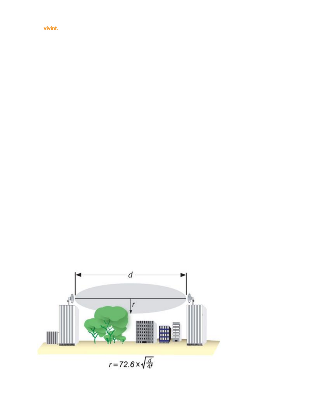
1.1.2 Radio Path Planning
The wireless router link requires a “radio line of sight” between the two antennas for optimum
performance.
The concept of radio line of sight involves the area along a link through which the bulk of the radio
signal power travels. This area is known as the first Fresnel Zone of the radio link. For a radio link, no
object (including the ground) must intrude within 60% of the first Fresnel Zone.
The following figure illustrates the concept of a good radio line of sight.
SR1410 Installation & User Guide Ver. 0.01
Page 11
SR1410 Installation and User Guide
Page 11
If there are obstacles in the radio path, there may still be a radio link but the quality and strength of the
signal will be affected. Calculating the maximum clearance from objects on a path is important as it
directly affects the decision on antenna placement and height. It is especially critical for long-distance
links, where the radio signal could easily be lost.
NOTE: For wireless links less than 500 m, the IEEE 802.11a radio signal will tolerate some obstacles in
the path and may not even require a visual line of sight between the antennas.
When planning the radio path for a wireless router link, consider these factors:
Avoid any partial line of sight between the antennas
Be cautious of trees or other foliage that may be near the path, or may grow and obstruct the
path
Be sure there is enough clearance from buildings and that no building construction may
eventually block the path
Check the topology of the land between the antennas using topographical maps, aerial
photos, or even satellite image data (software packages are available that may include this
information for your area)
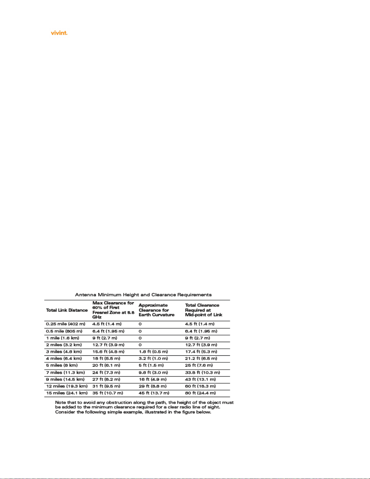
1.2 Antenna Height
A reliable wireless link is usually best achieved by mounting the antennas at each end high enough for a
clear radio line of sight between them. The minimum height required depends on the distance of the link,
obstacles that may be in the path, topology of the terrain, and the curvature of the earth (for links over 3
miles). For long-distance links, the AP may have to be mounted on masts or poles that are tall enough to
attain the minimum required clearance. Use the following table to estimate the required minimum
clearance above the ground or path obstruction (for 5 GHz router links).
SR1410 Installation & User Guide Ver. 0.01
Page 12

SR1410 Installation and User Guide
Page 12
1.2.1 Antenna Position and Polarization
Once the required antenna height has been determined, other factors affecting the precise position of the
wireless router must be considered:
Be sure there are no other radio antennas within 2 m (6 ft) of the wireless router. These include other
WiFi radio antennas
Place the wireless router away from power and telephone lines
Avoid placing the wireless router too close to any metallic reflective surfaces, such as roof-installed
air-conditioning equipment, tinted windows, wire fences, or water pipes. Ensure that there is at least 5
feet clearance from such objects
The wireless router antennas at both ends of the link must be positioned with the same polarization
direction, either horizontal or vertical. Proper alignment helps to maximize throughput.
The wireless router’s integrated antenna sends a radio signal that is polarized in a particular direction.
The antenna’s receive sensitivity is also higher for radio signals that have the same polarization. To
maximize the performance of the wireless link, both antennas must be set to the same polarization
direction.
1.2.2 Radio Interference
The avoidance of radio interference is an important part of wireless link planning. Interference is caused
by other radio transmissions using the same or an adjacent channel frequency. You should first scan your
proposed site using a spectrum analyzer to determine if there are any strong radio signals using the
802.11a,n channel frequencies. Always use a channel frequency that is furthest away from another
signal.
If radio interference is still a problem with your wireless link, changing the antenna polarization
direction may improve the situation.
1.2.3 Weather Conditions
When planning wireless links, you must take into account any extreme weather conditions that are
known to affect your location. Consider these factors:
Temperature — The wireless router is tested for normal operation in temperatures from -33°C to
55°C. Operating in temperatures outside of this range may cause the unit to fail.
Wind Velocity — The wireless router can operate in winds up to 90 miles per hour and survive
higher wind speeds up to 125 miles per hour. You must consider the known maximum wind velocity
and direction at the site and be sure that any supporting structure, such as a pole, mast, or tower, is
built to withstand this force.
Lightning — The wireless router includes its own built-in lightning protection via chassis grounding.
However, you should make sure that the unit, any supporting structure, and cables are all properly
grounded. Additional protection using lightning rods, lightning arrestors, or surge suppressors may
also be employed.
Rain — The SR1410 is weatherproofed against rain. Also, prolonged heavy rain has no significant
effect on the radio signal. However, it is recommended to use weatherproof boots on cables
connecting to the SR1410 or to apply weatherproof sealing tape around connectors for extra
SR1410 Installation & User Guide Ver. 0.01
Page 13

SR1410 Installation and User Guide
Page 13
protection. If moisture enters a connector, it may cause a degradation in performance or even a
complete failure of the link.
Snow and Ice — Falling snow, like rain, has no significant effect on the radio signal. However, a
buildup of snow or ice on antennas may cause the link to fail. In this case, the snow or ice
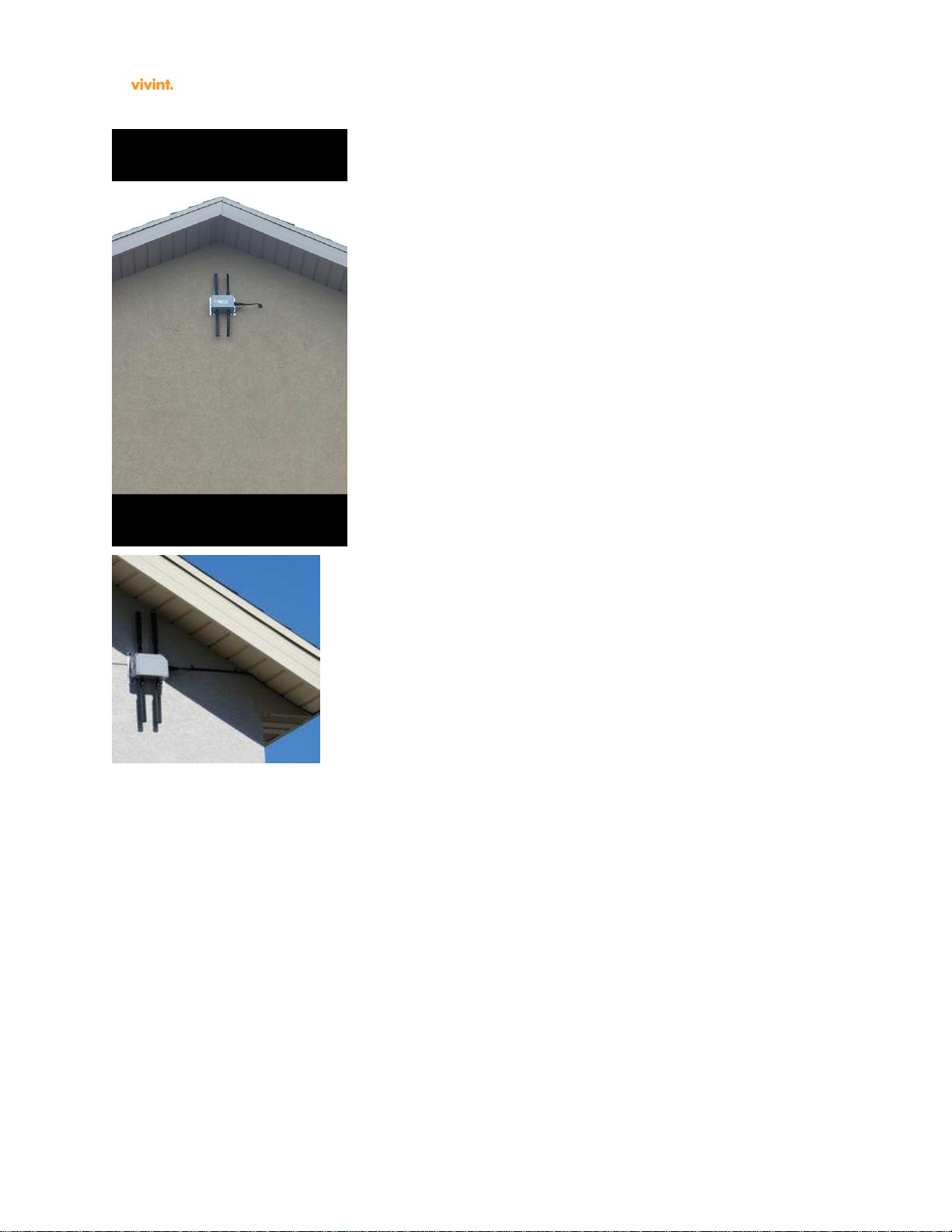
1.3 Ethernet Cabling
When a suitable antenna location has been determined, you must plan a cable route from the SR1410
wireless router outdoors to the equipment indoors. If a power injector/adapter module is used, it is for
indoor installation only. Consider these points:
The Ethernet cable length should never be longer than 90 m (295 ft)
Determine a building entry point for the cable
Determine if conduits, bracing, or other structures are required for safety or protection of the cable
For lightning protection at the power injector end of the cable, consider using
Example Installations:
SR1410 Installation & User Guide Ver. 0.01
Page 14
SR1410 Installation and User Guide
Page 14
SR1410 Installation & User Guide Ver. 0.01
Page 15

SR1410 Installation and User Guide
Page 15
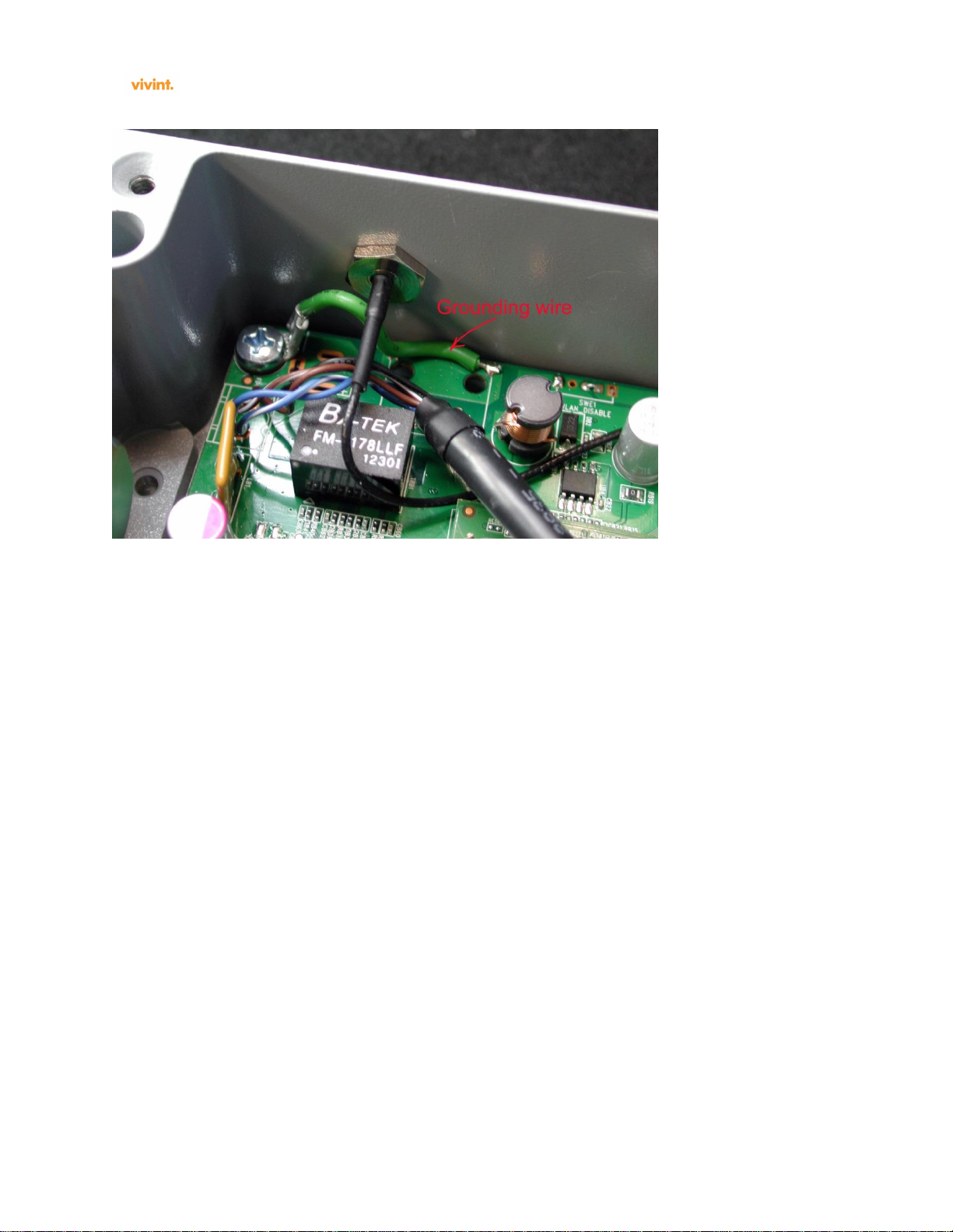
1.4 Grounding
It is important that the wireless router, cables, and any supporting structures are properly grounded. The
wireless router unit includes a grounding screw for attaching a ground wire. Be sure that grounding is
available and that it meets local and national electrical codes.
SR1410 Installation & User Guide Ver. 0.01
Page 16

SR1410 Installation and User Guide
Page 16
SR1410 Installation & User Guide Ver. 0.01
Page 17
SR1410 Installation and User Guide
Page 17
1.5 System Setup
1.5.1 Factory Default Configuration
To reset to factory defaults, login as ‘root’ and issue the command ‘restore_default_config’. The
command will first backup the current configuration to a TFTP server first before restoring the
configuration to factory defaults.
1.5.2 Connecting SR1410 for the First Time
Default factory password for ‘root’ account is ‘turnkey’.
Factory default IP address for eth0 is 192.168.1.100
SR1410 Installation & User Guide Ver. 0.01
Page 18

SR1410 Installation and User Guide
Page 18
1.5.3 Using the Web-based Configuration Setup Wizard
Provision the ‘eth0’ interface on SR1410 to be in the default subnet as the accessing machine and use
HTTP to access the node.
SR1410 console:
root@Vivint:~# ifconfig eth0 192.168.1.1 netmask 255.255.255.0 up
Accessing computer:
http://192.168.1.100/
1.6 System Configuration
SR1410 Installation & User Guide Ver. 0.01
Page 19

SR1410 Installation and User Guide
Page 19
SR1410 Installation & User Guide Ver. 0.01
Page 20

SR1410 Installation and User Guide
Page 20
1.7 Advanced Configuration
1.8 Traffic Control
SR1410 Installation & User Guide Ver. 0.01
Page 21

SR1410 Installation and User Guide
Page 21
The Hierarchical Token Bucket[HTB] creates a hierarchy of software queues called qdiscs which
represent the flow of traffic on a network interface. A parent (base) qdisc can have multiple child qdiscs
which in turn can be parents to other qdiscs. A leaf qdisc is the one which has no children.
The HTB is a classfull qdisc which means that traffic flowing through the interface can be classified into
flows. The classification can be performed using various filters assigned to the qdisc. The parameter
"rate" in the above command specifies the base or guaranteed bit rate of the qdisc corresponding to the
class. The parameter burst corresponds to the amount of data in bytes that will be processed at a time for
that qdisc. For an ingress qdisc it represents the bytes send up to the network stack for processing. For an
egress qdisc it represents the amount of data sent to the hardware for transmitting out. The parameter
"ceil" or ceiling represents the maximum bit rate for the qdisc. HTB qdiscs have the capability to borrow
bandwidth from peers which will be explained in the subsequent sections.
Example: tc class add dev eth0 parent 1:1 classid 1:10 htb rate 50mbit burst 1mbit ceil 60mbit
tc class add dev eth0 parent 1:1 classid 1:11 htb rate 20mbit burst 1mbit ceil 40mbit
The above commands create qdiscs of class labeled "1:10" and "1:11" for the qdisc "1:1". The parameter
"rate" represents the guaranteed or base bit rate for the qdiscs. The parameter "burst" is the amount of
data transmitted/received for the qdisc in a given time period. The parameter "ceil" is the maximum bit
rate for the qdisc. As mentioned before peer qdiscs can borrow bandwidth from each other if one of the
qdiscs is using less than base bandwidth or there is unused bandwidth available. Suppose qdisc 1:10 uses
50mbits but requires a total of 60mbps due to the bandwidth intensive nature of the application.. On the
other hand class 1:11 is using 10mbits out of the assigned 20mbits base bandwidth. In this case class
1:10 can borrow the additional 10mbps from 1:11 and use up its maximum assigned bandwidth of
60mbps.
SR1410 Installation & User Guide Ver. 0.01
Page 22

SR1410 Installation and User Guide
Page 22
1.9 NAT/Firewall
1.10 Routing Protocols
All Routing protocols can be started from CLI or from the web-interface. Mesh links are ad-hoc links.
In ad-hoc networks, nodes do not start out familiar with the topology of their networks; instead, they
have to discover it. The basic idea is that a new node may announce its presence and should listen for
announcements broadcast by its neighbors. Each node learns about nodes nearby and how to reach them,
and may announce that it, too, can reach them.
IP routing protocol which is optimized for mobile ad-hoc networks but can also be used on other
wireless ad-hoc networks. SR1410 uses proactive link-state routing protocol which uses Hello and
Topology Control (TC) messages to discover and then discriminate link state information throughout the
mobile ad-hoc network. Individual nodes use this topology information to compute next hop destinations
for all nodes in the network using shortest hop forwarding paths.
SR1410 Installation & User Guide Ver. 0.01
Page 23

SR1410 Installation and User Guide
Page 23
1.10.1 OSPF
SR1410 Installation & User Guide Ver. 0.01
Page 24

SR1410 Installation and User Guide
Page 24
Example:
!
! Zebra configuration saved from vty - zebra.conf
! 2009/07/10 23:30:56
!
hostname mpp
password mysecret
enable password mysecret
!
interface eth0
link-detect
multicast
!
interface eth1
link-detect
multicast
!
interface lo
!
interface ra_sta0
link-detect
multicast
!
interface ra_sta1
link-detect
multicast
!
interface ra_ap0
link-detect
multicast
!
interface ra_ap1
link-detect
multicast
!
ip forwarding
ipv6 forwarding
!
!
line vty
!
!
! Zebra configuration saved from vty – ospfd.conf
! 2009/07/10 23:36:59
!
hostname mpp
password mysecret
enable password mysecret
log stdout
!
!
!
interface eth0
!
interface eth1
!
interface lo
!
interface ra_sta0
!
interface ra_sta1
!
interface ra_ap0
!
interface ra_ap1
!
router ospf
ospf router-id 192.168.249.5
redistribute connected
network 192.168.249.0/24 area 0.0.0.0
network 10.131.5.0/24 area 0.0.0.0
network 10.15.0.0/24 area 0.0.0.0
network 10.17.0.0/24 area 0.0.0.0
network 10.130.9.0/24 area 0.0.0.0
network 10.131.9.0/24 area 0.0.0.0
!
line vty
!
For each of the networks present at the mesh router, a line is inserted to instruct the OSPF protocol to
advertise the routes to its neighbor/s.
1.10.2 RIP
Distance vector Routing Information Protocol[RIP] configuration file is located at
/usr/local/etc/ripd.conf
1.10.3 IGMP
Internet Group Management Protocol[IGMP] configuration file is located at /usr/local/etc/igmpd.conf
1.10.4 PIM
Protocol Independent Multicast[PIM] configuration is located at /usr/local/etc/pimd.conf
1.10.5 BGP
Border Gateway Protocol [BGP] configuration is located at /usr/local/etc/bgpd.conf
1.11 Multicast Control
Multicast servers and clients can be on any of the node interfaces. To provision multicast rules, the
source and destination of the stream and the multicast address on which the stream flows needs to be
identified. The screen below shows a typical multicast configuration.
SR1410 Installation & User Guide Ver. 0.01
Page 25

SR1410 Installation and User Guide
Page 25
Example: To enable multicast flows from 192.168.1.92 [attached on the wired segment – eth0] IGMP
multimedia server, to all wireless [ra_ap0] clients who are recipients, insert a rule as shown. There can
be multiple rules and these rules are launched upon restart of mesh router.
Upon provisioning the multicast rule, the node boot script is updated. The multicast rules take affect
upon reboot of the node. The boot script shown below illustrates the rule entry.
1.12 Administration
1.12.1 Adding Users & Changing Password
Usage: adduser [OPTIONS] user_name
Add an user
Options:
-h DIR Home directory
-g GECOS GECOS field
-s SHELL Login shell
-G GROUP Add user to existing group
-S Create a system user
-D Do not assign a password
-H Do not create home directory
Usage: passwd
Change password of an user
1.12.2 Upgrading Firmware
The System Reset directly resets the microprocessor and the on-board flash memory (as opposed to the
Compact Flash memory). Assertion of the System Reset causes an IO Reset to be asserted.
The System Reset is asserted by any of the following conditions:
An assertion of the Power-On Reset
A press of the reset button
A watchdog timeout
SR1410 Installation & User Guide Ver. 0.01
Page 26

SR1410 Installation and User Guide
Page 26
1.13 System Log
/var/log/message keeps a circular log in memory, no filesystem activity involved.
1.13.1 Enabling System Logging
To read the logfile from syslogd you should use the logread command, which outputs the messages in
syslogd's circular buffer.
Logging is always enabled.
1.14 DHCP Configuration
The SR1410 can be configured as a controller less Mesh Point Portal [MPP] or a controller based Mesh
Point [MP]. When configured as MPP, the DHCP addresses are allocated by the node itself. The DHCP
Directives in the main configuration screen drive the behavior of the mesh node.
Normally, the dhcp server running on the network manager serves all the clients connecting to the nodes
within a mesh block.
The dhcp server needs to be aware of the subnets at the mesh node access points and be able to assign
dynamic addresses based on those subnets.
The dhcp server shall assign a common dns server to all the clients within the mesh block.
The dhcp server shall be aware of the mesh node access point IP address from which the dhcp lease
request is received for a client. This AP address is the default router which shall be assigned to the client
requesting dhcp lease.
The Mesh block network topology comprises several nodes and each node may have an AP within a
subnet different from that of the DHCP interface. It is therefore necessary that the DHCP server detect
the subnet of the AP from which the DHCP request was originally received on behalf of a client. Once it
has the subnet information of this AP, it should assign the requesting client an IP address within the
same subnet as the AP.
The SR1410 can also be operated an MP where it relies on the network manager to allocate DHCP
addresses. On the other hand, it can also act as a DHCP server for a cluster of MPs. The node that is
elected to run DHCP service is the MPP.
SR1410 Installation & User Guide Ver. 0.01
Page 27

SR1410 Installation and User Guide
Page 27
SR1410 Installation & User Guide Ver. 0.01
Page 28

SR1410 Installation and User Guide
Page 28
Network, DHCP Server sub-menu, contains the network address, subnet, and range as shown in example
below.
authoritative;
ddns-update-style interim;
default-lease-time 600;
max-lease-time 1200;
option domain-name "dtsdcinema.com";
option domain-name-servers 192.168.249.1;
subnet 10.131.5.0 netmask 255.255.255.0 {
range 10.131.5.60 10.131.5.200;
option broadcast-address
10.131.5.255;
}
subnet 10.130.9.0 netmask 255.255.255.0 {
range 10.130.9.60 10.130.9.200;
option broadcast-address
10.130.9.255;
}
subnet 10.131.9.0 netmask 255.255.255.0 {
range 10.131.9.60 10.131.9.200;
option broadcast-address
10.131.9.255;
}
subnet 10.150.9.0 netmask 255.255.255.0 {
range 10.150.9.60 10.150.9.200;
option broadcast-address
10.150.9.255;
}
subnet 10.151.9.0 netmask 255.255.255.0 {
range 10.151.9.60 10.151.9.200;
option broadcast-address
10.151.9.255;
}
subnet 10.140.9.0 netmask 255.255.255.0 {
range 10.140.9.60 10.140.9.200;
option broadcast-address
10.140.9.255;
}
subnet 10.141.9.0 netmask 255.255.255.0 {
range 10.141.9.60 10.141.9.200;
option broadcast-address
10.141.9.255;
}
subnet 10.150.5.0 netmask 255.255.255.0 {
range 10.150.5.60 10.150.5.200;
option broadcast-address
10.150.5.255;
}
subnet 10.151.5.0 netmask 255.255.255.0 {
range 10.151.5.60 10.151.5.200;
option broadcast-address
10.151.5.255;
}
subnet 10.140.5.0 netmask 255.255.255.0 {
range 10.140.5.60 10.140.5.200;
option broadcast-address
10.140.5.255;
}
subnet 10.141.5.0 netmask 255.255.255.0 {
range 10.141.5.60 10.141.5.200;
option broadcast-address
10.141.5.255;
}
subnet 192.168.249.0 netmask 255.255.255.0
{
}
1.15 Site Survey
Radio frequencies in the neighborhood can be scanned and reported.
Monitoring menu tab and “Neighborhood Info” will output results.
1.16 Status Information
Status of the radio or interfaces can be queried through commands iwconfig and ifconfig
SR1410 Installation & User Guide Ver. 0.01
Page 29

SR1410 Installation and User Guide
Page 29
1.16.1 AP Status
root@Vivint:/etc/init.d# iwconfig
lo no wireless extensions.
eth1_0 no wireless extensions.
br0 no wireless extensions.
wifi0 IEEE 802.11na40 ESSID:"bh3-ap" Nickname:""
Mode:Master Frequency:5.5 GHz Access Point: AC:8D:14:00:07:3A
Bit Rate:0 kb/s Tx-Power:0 dBm Sensitivity=1/1
Retry:off RTS thr:off Fragment thr:off
Encryption key:1A13-B96F-9901-9FD3-2D35-3BBA-4D5D-9BFC Security mode:restricted
Power Management:off
Link Quality=0/70 Signal level=0 dBm Noise level=-181 dBm
Rx invalid nwid:0 Rx invalid crypt:0 Rx invalid frag:0
Tx excessive retries:55 Invalid misc:3986 Missed beacon:0
SR1410 Installation & User Guide Ver. 0.01
Page 30

SR1410 Installation and User Guide
Page 30
SR1410 Installation & User Guide Ver. 0.01
Page 31

SR1410 Installation and User Guide
Page 31
2.0 Hardware Installation
The SR1410 Outdoor Wireless Access Point/Router is designed to be deployed outdoors, exposed to all
elements (extreme heat or sun, rain, snow, ice, cold) and mounted on a wall, pole, or mast. The SR1410
is supplied complete with its own mounting hardware kit for attaching the unit to a 1-2.5” diameter metal
pole or tube or as part of a radio mast or tower structure.
The supplied SR1410 48V power supply is suitable for outdoor use.
The optional SR1410 indoor-rated Power over Ethernet injector (Vivint part #9004H49000) must be
deployed indoors, or within an enclosure protecting it from the elements.
Hardware installation of the wireless router involves these steps:
1. Mount the SR1410 unit on a wall, pole, mast, or tower using the mounting hardware.
2. Mount external antennas on the same supporting structure as the router and connect them
to the router unit.
3. Connect a grounding wire to the SR1410 unit.
4. Connect the Ethernet cable to the SR1410 unit.
5. Connect the power supply to the SR1410, and to an AC power source.
6. Connect the power injector (if used) to the Ethernet cable, a local LAN switch, and an AC
power source.
7. Align antennas at both ends of the link.
Before mounting antennas to set up your wireless links, be sure you have selected appropriate locations
for each antenna. Follow the guidance and information in “Link Planning.”
Also before mounting units in their intended locations, you should first configure the devices as
described in Section 1.5 “System Setup” and Section 1.6 , “System Configuration.” You should also test
the basic operation of the wireless router links in a controlled environment over a very short range, as
described in “Testing Basic Link Operation”, Section 2.1.1.
2.1 Before Installing
Before installing your SR1410 Outdoor Wireless Access Point/Router, verify that you have the
following:
Outdoor Ethernet cable of required length of 50 meters (164 feet), or a cable meeting the pin-out
configuration specification to the required length (not to exceed 90 meters total), shielded CAT-5
Ethernet 8-pin DIN to RJ-45
Power supply shipped with the SR1410
An appropriate and stable mounting location
A suitable electrical grounding point (on AP mounting mast/pole)
Appropriate tools (wrench for mounting bolts, Phillips head screwdriver, DC voltmeter (if RSSI-
based link alignment is to be performed))
Mounting items not supplied with the SR1410 — screws, bolts, and straps — should be available and at
hand prior to installation.
SR1410 Installation & User Guide Ver. 0.01
Page 32

SR1410 Installation and User Guide
Page 32
Due to the typically inaccessible location often best suited to deploying an outdoor wireless router (for
example, on rooftops, sides of buildings, or on a radio tower) it is recommended that the network
administrator pre-provision the SR1410 system to be installed (taking note of settings, passwords,
Channel, MAC and IP addresses) prior to physical installation, and confirm that the device is fully
operational and free from fault.
2.1.1 Testing Basic Link Operation
Set up the units over a very short range (15 to 25 feet), either outdoors or indoors. Connect the units as
indicated in this chapter and be sure to perform all the basic configuration tasks outlined in “System
Setup.” When you are satisfied that the links are operating correctly, proceed to mount the units in their
intended locations.
2.2 Connect External Antennas
When deploying a SR1410 Master router unit for a router link or an access point operation, you need to
mount external antennas and connect them to the router. Typically, a router link requires a 5 GHz
antenna, and an access point or station operation.
Perform these steps:
1. Mount the external antenna to the same supporting structure as the router, within 3 m (10 ft) distance,
using the bracket supplied in the antenna package.
2. Connect the antenna to the router’s N-type connector using the RF coaxial adapter provided in the
antenna package.
3. Apply weatherproofing tape to the antenna connectors to help prevent water entering the connectors.
2.2.1 Frequency, Wavelength and Velocity
Instead of saying “cycles per second”, we use the word Hertz (abbreviated Hz) in honor of Heinrich
Hertz who discovered radio waves. Also, since we are dealing with high frequencies, we use prefixes
like kilo (1,000), Mega (1,000,000) and Giga (1,000,000,000) in front of Hertz, to further simplify the
terminology.
5 cycles per second = 5 Hz
5,000 cycles per second = 5 kHz
5,000,000 cycles per second = 5 MHz
5,000,000,000 cycles per second = 5 GHz
We know that radio waves travel at the speed of light (~186,000 miles per sec. or 3 x 10⁸ meters per
sec.) and we can measure the frequency of the radio waves, therefore we can find out how far the wave
travels in 1 cycle by dividing its’ speed by its’ frequency. We call this a wavelength
Frequency Wavelength
150 MHz 2.0 m
900 MHz 33.3cm
SR1410 Installation & User Guide Ver. 0.01
Page 33

SR1410 Installation and User Guide
Page 33
2.4 GHz 12.5cm
5.8 GHz 52cm
2.2.2 The Decibel
The decibel (dB) is a ratio, measured in logarithm, used to measure quantity. A dB has no dimensions.
The decibel is used to compare one power (or voltage level) to another.
Ratio in dB = 10log10 (Power Ratio) = 20log10 (Voltage Ratio)
(Power is proportional to the voltage squared)
20 dB means a power ratio of 102 to 1 or 1,000:1
10 dB means a power ratio of 10 to 1 or 100:1
0 dB means a power ratio of 1 to 1 or 1:1
Because the dB is a ratio, it is dimensionless, however many times reference is made to the unit that is
made as a ratio.
e.g. dBm in the case of milliwatts 20 dBm means 100:1 over 1 milliwatt or 100mW
e.g. converting 4W into dBm 10log10 4000mW / 1mW = 36 dBm
Later on we will see that if an antenna has twice the power gain of a half wave dipole (an antenna used
as a standard reference), that is a power ratio of 2 over the 1/2 wave dipole, then the antenna is said to
have a gain of 3dBd. (3db over the1/2 wave dipole)
10log2=3
A +3dB gain represents a doubling of power while a -3dB loss represents 1/2 of the power
2.3 Align Antenna
After wireless router units have been mounted, connected, and their radios are operating, the antennas
must be accurately aligned to ensure optimum performance on the router links. This alignment process is
particularly important for long-range point-to-point links. In a point-to-multipoint configuration the
SR1410 uses an omni-directional or sector antenna, which does not require alignment.
SR1410 Installation & User Guide Ver. 0.01
Page 34

SR1410 Installation and User Guide
Page 34
Point-to-Point Configurations – In a point-to-point configuration, the alignment process requires
two people at each end of the link. The use of cell phones or two-way radio communication may help
with coordination. To start, you can just point the antennas at each other, using binoculars or a
compass to set the general direction. For accurate alignment, you must set the transmitter to output in
continuous transmit mode, and set the receiver to be in continuous receive frame mode. As the
antenna moves horizontally and vertically, the RSSI values vary and are indicated on the management
interface.
Point-to-Multipoint Configurations – In a point-to-multipoint configuration all Slave routers must
be aligned with the Master router antenna. The alignment process is the same as in point-to-point
links, but only the Slave end of the link requires the alignment.
Steps for aligning antenna:
Initialize the transmitting radio to be in continuous transmit mode. The interface shall be enabled at the
main screen as shown below, by selecting the red rectangle on mouse-over
2.4 Command Line Interface
Commands that perform the most functions are:
ifconfig – Network related
iwpriv – WLAN related
iwconfig – WLAN related
iptables – Traffic filter, classification, forwarding, NAT
tc – traffic queuing
2.4.1 Getting Help on CLI Commands
2.4.1.1 ifconfig
root@Vivint:~# ifconfig --help
BusyBox v1.11.2 (2010-08-07 08:17:48 PDT) multi-call binary
Usage: ifconfig [-a] interface [address]
Configure a network interface
Options:
[add ADDRESS[/PREFIXLEN]]
[del ADDRESS[/PREFIXLEN]]
[[-]broadcast [ADDRESS]] [[-]pointopoint [ADDRESS]]
[netmask ADDRESS] [dstaddr ADDRESS]
[hw ether ADDRESS] [metric NN] [mtu NN]
SR1410 Installation & User Guide Ver. 0.01
Page 35

SR1410 Installation and User Guide
Page 35
[[-]trailers] [[-]arp] [[-]allmulti]
[multicast] [[-]promisc] [txqueuelen NN] [[-]dynamic]
[up|down] ...
2.4.1.2 iwpriv
root@Vivint:~# iwpriv --help
Usage: iwpriv interface [private-command [private-arguments]]
2.4.1.3 iptables
root@Vivint:~# iptables --help
iptables v1.4.0
Usage: iptables -[AD] chain rule-specification [options]
iptables -[RI] chain rulenum rule-specification [options]
iptables -D chain rulenum [options]
iptables -[LFZ] [chain] [options]
iptables -[NX] chain
iptables -E old-chain-name new-chain-name
iptables -P chain target [options]
iptables -h (print this help information)
Commands:
Either long or short options are allowed.
--append -A chain Append to chain
--delete -D chain Delete matching rule from chain
--delete -D chain rulenum
Delete rule rulenum (1 = first) from chain
--insert -I chain [rulenum]
Insert in chain as rulenum (default 1=first)
--replace -R chain rulenum
Replace rule rulenum (1 = first) in chain
--list -L [chain] List the rules in a chain or all chains
--flush -F [chain] Delete all rules in chain or all chains
--zero -Z [chain] Zero counters in chain or all chains
--new -N chain Create a new user-defined chain
--delete-chain
SR1410 Installation & User Guide Ver. 0.01
Page 36

SR1410 Installation and User Guide
Page 36
-X [chain] Delete a user-defined chain
--policy -P chain target
Change policy on chain to target
--rename-chain
-E old-chain new-chain
Change chain name, (moving any references)
Options:
--proto -p [!] proto protocol: by number or name, eg. `tcp'
--source -s [!] address[/mask]
source specification
--destination -d [!] address[/mask]
destination specification
--in-interface -i [!] input name[+]
network interface name ([+] for wildcard)
--jump -j target
target for rule (may load target extension)
--goto -g chain
jump to chain with no return
--match -m match
extended match (may load extension)
--numeric -n numeric output of addresses and ports
--out-interface -o [!] output name[+]
network interface name ([+] for wildcard)
--table -t table table to manipulate (default: `filter')
--verbose -v verbose mode
--line-numbers print line numbers when listing
--exact -x expand numbers (display exact values)
[!] --fragment -f match second or further fragments only
--modprobe=<command> try to insert modules using this command
--set-counters PKTS BYTES set the counter during insert/append
[!] --version -V print package version
2.4.1.4 tc
root@Vivint:~# tc
Usage: tc [ OPTIONS ] OBJECT { COMMAND | help }
SR1410 Installation & User Guide Ver. 0.01
Page 37

SR1410 Installation and User Guide
Page 37
tc [-force] -batch file
where OBJECT := { qdisc | class | filter | action | monitor }
OPTIONS := { -s[tatistics] | -d[etails] | -r[aw] | -b[atch] [file] }
2.4.1.5 iwconfig
root@Vivint:~# iwconfig --help
Usage: iwconfig [interface]
interface essid {NNN|any|on|off}
interface mode {managed|ad-hoc|master|...}
interface freq N.NNN[k|M|G]
interface channel N
interface bit {N[k|M|G]|auto|fixed}
interface rate {N[k|M|G]|auto|fixed}
interface enc {NNNN-NNNN|off}
interface key {NNNN-NNNN|off}
interface power {period N|timeout N|saving N|off}
interface nickname NNN
interface nwid {NN|on|off}
interface ap {N|off|auto}
interface txpower {NmW|NdBm|off|auto}
interface sens N
interface retry {limit N|lifetime N}
interface rts {N|auto|fixed|off}
interface frag {N|auto|fixed|off}
interface modulation {11g|11a|CCK|OFDMg|...}
interface commit
3.0 Specifications
3.1 Product features
Wireless accesspoint and station
Various antenna options
Protocol-independent networking functionality
Supports IEEE 802.11n, 40Mhz operation as an AP
Supports IEEE 802.11n, 40 Mhz operation as an STA
Seamless connectivity to wired LANs augment existing networks quickly and easily
SR1410 Installation & User Guide Ver. 0.01
Page 38

SR1410 Installation and User Guide
Page 38
3.2 Ethernet Compatibility
The SR1410 Outdoor Wireless Access Point/router attaches to 10/100 Mbps Ethernet (FE) LAN
segments that utilize 10Base-T/100Base-TX (twisted-pair) wiring. The device appears as an Ethernet
node and performs a routing function by moving packets between the wired LAN and remote
workstations on the wireless infrastructure.
3.3 Power Over Ethernet
The SR1410 Outdoor Wireless Access Point/router supports non-standard Power Over Ethernet (POE)
3.4 Radio Characteristics
The SR1410 Outdoor Wireless Access Point/router can be configured to support IEEE 802.11n
operation as an AP or STA, and supports both IEEE 802.11n and IEEE 802.11n operation as an AM
(where allowed):
802.11n provides a high data rate and reliable wireless connectivity 802.11n operation uses a
radio modulation technique known as Orthogonal Frequency Division Multiplexing (OFDM), and
a shared collision domain (CSMA/CA). It operates in the 5 GHz Unlicensed National Information
Infrastructure (UNII) band. Data is transmitted over a half-duplex radio channel operating at up to
300 Megabits per second (Mbps)
SR1410 Installation & User Guide Ver. 0.01
 Loading...