

VividImage MON-VTS24HD2, MON-VTS24HD2M, MON-VTS26HD2M, MON-VTS26HD2, MON-VTS24HD2R Operation Manual
...
VividImage
LCD Surgical Grade Monitor
High Definition Wide Screen
®
OPERATION MANUAL
MON-VTS24HD2
MON-VTS26HD2
MON-VTS24HD2M
MON-VTS26HD2M
MON-VTS24HD2R
MON-VTS26HD2R
MON-VTS24HD2MR
MON-VTS26HD2MR
MON-VTS26HD2

Notice for Users
IMPORTANT:
To aid in reporting in the case of loss or theft, or for
service maintenance purposes, please record the
monitor’s part number and serial number in the
space provided. The numbers are located on the
back of the monitor.
FCC Statement
WARNING – FCC Regulations state that any unauthorized changes or modifications to this equipment
not expressly approved by the manufacturer could void the user’s authority to operate this equipment.
Note: This equipment has been tested and found to comply with the limits for a Class A digital device,
pursuant to Part 15 of the FCC Rules.
These limits are designed to provide reasonable protection against harmful interference when the
equipment is operated in a commercial environment. This equipment generates, uses, and can radiate
radio frequency energy and, if not installed and used in accordance with the instruction manual, may
cause harmful interference to radio communications. Operation of this equipment in a residential area is
likely to cause harmful interference in which case the user will be required to correct the interference at
his own expense.
For part numbers MON-VTS24HD2, MON-VTS24HD2R, MON-VTS26HD2 and MON-VTS26HD2R use
only the included power supply, model WSX624M, manufactured by Jerome Industries, to insure
compliance with FCC regulations.
Declaration of Conformity
VividImage
MON-VTS24HD2 / MON-VTS24HD2M / MON-VTS26HD2 / MON-VTS26HD2M
MON-VTS24HD2R / MON-VTS24HD2MR / MON-VTS26HD2R / MON-VTS26HD2MR:
This device complies with Part 15 of the FCC Rules. Operation is subject to the following two conditions:
(1) this device may not cause harmful interference, and (2) this device must accept any interference
received, including interference that may cause undesired operation.
®
Medical Grade Monitor-
This device has been evaluated to the UL 60601-1 standard:
Equipment evaluated to this standard is not suitable for use in the presence of a flammable anesthetic
mixture with air or with oxygen or nitrous oxide (unless additional tests have been passed). Therefore
this device is not suitable for use in the presence of a flammable anesthetic mixture with air or with
oxygen or nitrous oxide.
Function, Intended Application and Mode of Operation:
The VividImage
graphics for review and analysis by trained medical practitioners. The mode of operation for this device
is continuous operation.
These devices are classified as Class 1 Equipment:
MON-VTS24HD2 / MON-VTS24HD2M / MON-VTS26HD2 / MON-VTS26HD2M
Accessory Equipment:
Accessory equipment connected to the analog and digital interfaces must be certified to the respective
IEC standards (i.e. IEC 950 for data processing equipment and IEC 60601-1 for medical equipment).
Furthermore all configurations shall comply with the system standard IEC 60601-1-1. Any equipment
connected to the signal input part or signal output part configures a medical system. Therefore this
equipment, and new configuration, must comply with the requirements of the system standard IEC
60601-1-1.
®
Series of monitors are intended to be used in the displaying and viewing of video and
Part No:
Serial No:
Document # Revision Date
82070-615, Revision F
2 of 25 2/23/2010
For a complete list of current certifications, please refer to the Specifications page of this manual.
UL Classified. See complete marking on product.
UL Classified part numbers:
MON-VTS24HD2
MON-VTS26HD2
MON-VTS24HD2M
MON-VTS26HD2M
The UL Classified part numbers above include a power supply, model WSX624M, manufactured by
Jerome Industries Corporation.
Recognized under the Component Recognition Program of Underwriters Laboratories Inc.
UL Component Recognition part numbers:
MON-VTS24HD2R
MON-VTS26HD2R
MON-VTS24HD2MR
MON-VTS26HD2MR
The UL Component Recognition part numbers above do not include a power supply.
The table below associates the Model Numbers that are UL Classified and Recognized with the VTS Part
Numbers for same.
UL Classified Model Numbers
VTS-24-HD003 MON-VTS24HD2 MON-VTS24HD2M
VTS-26-HD003 MON-VTS26HD2 MON-VTS26HD2M
UL Recognized Model Numbers
VTS-24-HD003R MON-VTS24HD2R MON-VTS24HD2MR
VTS-26-HD003R MON-VTS26HD2R MON-VTS26HD2MR
VTS Part Numbers
VTS Part Numbers
with Integrated Microphone
Document # Revision Date
82070-615, Revision F
3 of 25 2/23/2010

Table of Contents
NOTICE FOR USERS .................................................................................................................................... 2
FCC Statement................................................................................................................................................................. 2
Declaration of Conformity ................................................................................................................................................. 2
TIPS AND SAFETY PRECAUTIONS............................................................................................................. 5
Monitor and Accessory Checklists ................................................................................................................................... 5
Mounting........................................................................................................................................................................... 5
Location ............................................................................................................................................................................ 5
Power Cord....................................................................................................................................................................... 5
Manual Scope................................................................................................................................................................... 5
CONNECTING THE MONITOR AND TURNING ON/OFF ............................................................................. 6
Step 1: Unpacking the carton .......................................................................................................................................... 6
Step 2: Mounting the monitor .......................................................................................................................................... 6
Step 3: Attaching the monitor to a boom arm and connecting video and power sources ............................................... 6
Step 4: Connecting to Power........................................................................................................................................... 7
Figures 1A & 1B: Rear view and close up of ports, respectively ........................................................................ 8
Figure 2: Sample video source connections and power plug ............................................................................. 8
USER INTERFACE ........................................................................................................................................ 9
User Interface Buttons...................................................................................................................................................... 9
Figure 3: User Interface ........................................................................................................................................... 9
Power Control................................................................................................................................................................... 9
Video Source .................................................................................................................................................................... 9
Direct Black-Level Adjustment ......................................................................................................................................... 9
Keypad Lock..................................................................................................................................................................... 9
Main Menu........................................................................................................................................................................ 9
OSD (ON SCREEN DISPLAY) ......................................................................................................................10
Main Menu...................................................................................................................................................................... 10
Input................................................................................................................................................................................ 10
Black-Level..................................................................................................................................................................... 10
Contrast .......................................................................................................................................................................... 10
Color ............................................................................................................................................................................... 11
Geometry........................................................................................................................................................................ 12
PIP.................................................................................................................................................................................. 13
Enhancement ................................................................................................................................................................. 14
System............................................................................................................................................................................ 14
Figure 4: OSD Menu Navigation Options............................................................................................................. 18
Default Settings ............................................................................................................................................................ 19
Table 1: Default Settings ....................................................................................................................................... 19
MONITOR CARE / TROUBLESHOOTING....................................................................................................20
Monitor Care................................................................................................................................................................... 20
Storage ........................................................................................................................................................................... 20
Troubleshooting.............................................................................................................................................................. 20
SPECIFICATIONS...................................................................................................................................21
Table 2: Specifications .......................................................................................................................................... 21
GLOSSARY...................................................................................................................................................22
INDEX............................................................................................................................................................24
CONTACT CUSTOMER SUPPORT..............................................................................................................25
Document # Revision Date
82070-615, Revision F
4 of 25 2/23/2010
Tips and Safety Precautions
- Image persistence on LCD monitors is caused
by the continuous display of static graphics on
the screen for extended periods of time. Do not
display a static image for more than eight (8)
hours. An afterimage may remain.
- To prevent image persistence,
power off the monitor when not in
use, especially at the end of the
day.
- It may be difficult to see the image if the
brightness is adjusted to the minimum setting
(applicable only for 24” monitor).
- The quality of the video signal may influence the
quality of the displayed image.
- Do not open the monitor casing.
Monitor and Accessory Checklists
MON-VTS24HD2, MON-VTS24HD2M
MON-VTS26HD2, MON-VTS26HD2M
- Included in the carton are the following items:
1 VividImage
1 Cable Cover
(attached to the back of the monitor)
1 Power Supply*
1 Power Cord
8 Mounting Screws
(screwed into the back of the monitor)
1 Quick Start Guide
* Use only the Jerome Industries power supply,
model WSX624M included in the carton.
MON-VTS24HD2R, MON-VTS24HD2MR
MON-VTS26HD2R, MON-VTS26HD2MR
- Included in the carton are the following items:
1 VividImage
1 Cable Cover
(attached to the back of the monitor)
8 Mounting Screws
(screwed into the back of the monitor)
1 Quick Start Guide
- See Step 4 in the next section to connect part
numbers ending with “R” to power.
Notes:
- Retain the carton and packing material for
transporting the monitor.
Mounting
- Mounting the monitor to a boom arm requires
two people.
- Always follow mounting instructions to avoid
physical injury and/or damage to the monitor.
®
HD Monitor
®
HD Monitor
Location
- Use the monitor in a suitable environment. See
“Operating Temperature” and “Storage
Temperature” on the Specifications page of this
manual.
- Even though the monitor is classified as surgical
/ medical grade, use caution around liquids as
you would with any electrical appliance.
- Do not insert objects into the monitor.
- Do not place the monitor on unstable surfaces.
- In all cases, refer to the specifications in this
manual to ensure proper monitor performance.
Use of the monitor outside of operating
specifications will void the monitor warranty and
may cause permanent damage to the monitor.
- Note: This product contains fluorescent lamps;
please follow local ordinances or regulations for
disposal.
Power Cord
(Part numbers MON-VTS24HD2, MON-
VTS24HD2M, MON-VTS26HD2 and MONVTS26HD2M only.)
- Do not damage the power cord. Damage to the
cord may result in fire or electric shock.
- Do not add extension cords.
- Use only the power cord and power
supply included with the monitor.
- Insert the power plug directly into the AC outlet.
- Do not remove or insert the power plug with wet
hands. Doing so could result in electric shock.
Manual Scope
- This manual is written for use with
MON-VTS24HD2 / MON-VTS24HD2M
MON-VTS26HD2 / MON-VTS26HD2M
MON-VTS24HD2R / MON-VTS24HD2MR
MON-VTS26HD2R / MON-VTS26HD2MR
When describing a different specification /
function between the monitors, the part number,
or 24”, 26” is given. (When the part number is
not given, the description is true for all monitors.
For product appearance, illustrations of part
number MON-VTS26HD2 are used in this
manual.) “M” in the part number notates a
monitor with an integrated microphone. The
microphone is only operational when the
monitor is connected to an integrated video
system, sold separately. “R” at the end of a part
number indicates that the monitor is an
Underwriters Laboratories, Inc. Recognized
Component. All other part numbers are UL
Classified.
Document # Revision Date
82070-615, Revision F
5 of 25 2/23/2010

Connecting the Monitor and Turning On/Off
Step 1: Unpacking the carton
Included in the carton for part numbers MON-VTS24HD2, MON-VTS24HD2M, MON-VTS26HD2 and
MON-VTS26HD2M are the following items:
1 VividImage
1 Cable Cover (screwed onto the back of the monitor)
1 Power Cord
1 Power Supply
8 Mounting Screws (screwed into the back of the monitor)
1 Quick Start Guide
For part numbers MON-VTS24HD2R, MON-VTS24HD2MR, MON-VTS26HD2R and MON-VTS26HD2MR,
there is not an included Power Supply and Power Cord. (See Step 4, Connecting to Power.)
If any one of these items is missing, please call Customer Support at (877) 887-1788.
Step 2: Mounting the monitor
The back of the monitor (see Figure 1) has a hole pattern that complies to the VESA (Video Electronics
Standards Association) mounting standard. The monitor is shipped with eight screws that are screwed into
the back of the monitor. Four screws are ½″ long and four screws are ⅜″ long. Remove all eight screws
and use one set of four screws to attach the monitor to the mount, either in the inside square hole pattern,
75mm, or the outside square hole pattern, 100mm (see Figure 1A). Use the longer four screws for mounts
with thicker mounting plates. The mount is sold separately.
Note to users attaching the VividImage® Monitor to Operating Room Equipment Management System and/or
Equipment Boom:
If the VividImage
boom vendor should have wired the appropriate cables through the boom arm.
Step 3: Attaching the monitor to a boom arm and connecting video and power sources
1. Attaching the VividImage
2. One person should hold and support the monitor while the second person attaches the monitor to
the boom arm.
3. One person should align the monitor to the mounting holes while a second person physically
attaches the monitor to the VESA mount attached to the boom arm.
4. After the monitor is mounted, remove the cable cover and connect the customer supplied video
cable(s) and power cord, if applicable, to the appropriate port on the back of the monitor. The ports
on the monitor are clearly labeled (see Figure 1B). For a photo of possible video sources, see
Figure 2.
5. The cable cover should be re-attached using the included screws.
6. The monitor will turn on automatically once it is connected to a power source.
®
HD Monitor
®
Monitor is to be mounted on a boom and/or Equipment Management System, the
®
monitor to a boom arm requires two (2) people.
Document # Revision Date
82070-615, Revision F
6 of 25 2/23/2010

Step 4: Connecting to Power
For part numbers MON-VTS24HD2R, MON-VTS24HD2MR, MON-VTS26HD2R and MONVTS26HD2MR, please see the Quick Start Guide that is included in the monitor carton for instructions
on how to connect to power.
Document # Revision Date
82070-615, Revision F
7 of 25 2/23/2010
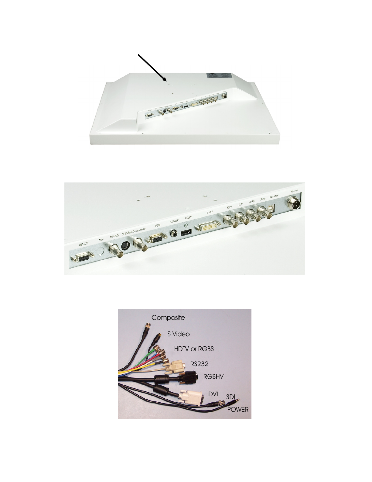
VESA Mounting Holes
Figures 1A & 1B: Rear view and close up of ports, respectively
Figure 2: Sample video source connections and power plug
Document # Revision Date
82070-615, Revision F
8 of 25 2/23/2010
 Loading...