

Page 1
Page 2
VIVID AUDIO
USER GUIDE
This manual applies to the following models:
K1, B1, C1, V1.5, and the V series.
TABLE OF CONTENTS
Page number
1 2 4 5 7 8 9
10
15
16
23
Content
Important information on unpacking and use
Introduction and positioning
Multi channel use
V1w wall mount
Connecting up
Spikes
Disclaimer
Specifications
Installation notes
Early loudspeaker history.
Contacting Vivid Audio
Page 3

Important Notes
The silver aluminium domed/coned drive units
are extremely sensitive. They must never be
subjected to probing fingers or other sharp
objects! If so, certain damage will result and a
replacement driver will have to be fitted.
This replacement will not be performed under
guarantee conditions.
Unpacking Instructions
Read these instructions that contain important
information about the safe use, installation and
maintenance of this loudspeaker.
• Unpack the loudspeaker following the instruction
sheet attached to the shipping crate. The method is also
described below. Check for damage. Keep potentially
hazardous packaging (plastic bags, polystyrene etc.) out
of reach of children.
• Dispose of packaging in compliance with current waste
disposal requirements.
1
Page 4

Introduction
We’re obviously very happy that you chose Vivid Audio Loudspeakers so please
spend a little time reading this manual to help ensure that you are equally happy
with your purchase.
These loudspeakers are the culmination of many years of research by our design
engineer Laurence Dickie and the R&D team in Durban. They feature a range of
unique drive units and enclosures which deliver an unprecedented purity of reproduced
sound. All our drivers include novel features, many of which have been patented.
A fundamental design philosophy has always been to keep resonances and the effects
of reflection well out of band and this applies just as much to our mid-range units
as to our tweeters so we don’t take a basically floppy cone and treat it until the
resonances are acceptable, we make jolly sure they are not there in the first place.
Similarly you may have noticed that the enclosures used in all Vivid Audio products
share a very rounded form. This not done for pure aesthetics but is there to completely
remove the effects of reflection from the edge of the cabinet.
Having perfected a driver and enclosure combination that deliver totally smooth
responses, the crossover designs are quite straightforward with no extra elements
required to make up for the deficiencies of the basic acoustic designs.
We follow the conventional rules for system design quite closely and find there is
no need to deviate from the path because we do not have to compensate for
driver idiosyncrasies.
So having taken all this trouble to develop the loudspeakers we feel it would be only
fair that you take the time to read these notes to help squeeze out as much of that
performance as possible into your listening space.
Positioning
Vivid Audio loudspeakers are designed with both home theatre and two channel
stereo application in mind and, because of the intrinsically shielded magnet structure,
all our products can be placed near to conventional tube televisions or computer
monitors if necessary.
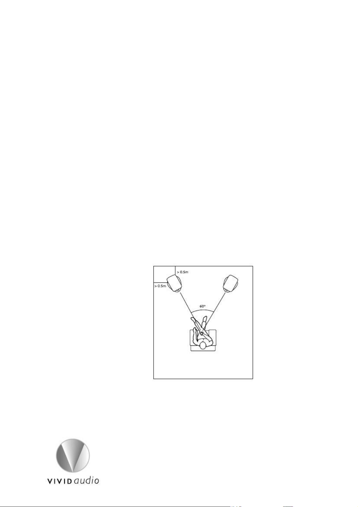
For two-channel installations we recommend as a starting point that you position
the loudspeakers at least 0.5m from the rear wall and, if anything, a little further
from the side walls if possible. Hving two different distances here will help to smooth
out the effects of the boundaries on the low frequencies and improve the sense of
space and scale of the performance.
As a general rule, the closer the speakers are to a wall the more the upper bass will
be accentuated. Conversely, if you move them away from the walls only the lower
bass will be reinforced. If the walls are of a light construction these reinforcement
effects will be reduced accordingly.
Furthermore, all rooms have resonances at a number of single frequencies that will
tend to be emphasised when the speakers are placed nearer the corners which can
cause ‘boominess’. So again, if these are problematic, try moving the speakers away
from the corners.
2
Page 5
Remember that all the rules which apply to the loudspeaker position also apply to
the listening position so if you find that the low frequencies are a little light because
you have placed your sofa in the middle of the room to be equidistant from the
surround speakers then you may recover some of this low end by moving the speakers
back towards the walls. Similarly, if you are in two channel mode with the listening
position close to the back wall and you have excessive bass, try moving away from
the wall.
One technique for finding the best speaker position which exploits this reciprocity
is to place a speaker at the listening position and to move around the room to find
places with an even bottom end. Then you can swap the speaker and listener and
find the same result. This only works for one speaker at a time and the results with
both speakers in position may not be quite as you expect so be prepared to try again.
A good listening position will often be found at the point where the loudspeakers
are about 60˚ apart, fig.1. Much closer together than this and the apparent image
width will suffer, much wider and you may find a ‘hole’ in the centre of the image,
particularly when seated off to one side.
There is no appreciable beam from any of the Vivid Audio loudspeaker drivers, that
is to say; the tonal balance is consistent across a wide angle as opposed to some
designs where the high frequencies in particular quickly fall in level as you move
away from a point directly in front of the speaker as if they were shining out from
a flashlight. It is our experience that, because of the very smooth wide sound field
produced by our designs, angling the loudspeakers so that they both face a position
just ahead of the listeners can help to widen the useful area where stereo sound may
be enjoyed.
Fig.1
An absence of beaming is also a feature in the vertical plane, so being absolutely at
the same level as the loudspeakers is not important. In fact a perfectly enjoyable
sound balance may be found when lying on the floor more or less anywhere between
the loudspeakers!
Because of the infinite number of combinations of wall materials dimensions and
furnishings in the room it is impossible to give more precise positioning advice than
that above. In the end we strongly recommend that you experiment, so if you are
going to fit the spikes to the bases then we suggest that you leave this until the
positions have been determined.
3
Page 6
Small Studio Monitoring
All Vivid Audio speakers make excellent small-scale studio monitors giving pin-point
imaging and incredible detail which are both indispensable qualities in such an
applications. B1 and K1 are balanced for flat response in a free field acoustic and
are thus best suited to very dry acoustics such as heavily damped studios or where
the desk and monitors are fairly well removed from the walls. In smaller rooms where
the desk is close to the walls, the V1 range or C1 may give a more natural balance.
In either case, you should really measure the response of the system at the listening
position and EQ accordingly.
Centre Speaker
With the introduction of a third, central channel, the sound stage tends to fill out
in the middle and the two main speakers may be positioned a little further apart,
or the listener a little closer, without suffering from holes in the image. If you are
positioning the speakers around a TV or monitor, it’s worth bearing in mind that the
sound stage is best kept in proportion to the size of the picture, so if you have a
35cm screen it might seem a bit disconcerting if the sound stage is as big as a house.
The C1 centre channel model is tonally balanced in such a way that it can be
positioned closer to the walls than either B1 or K1. Because of the broad vertical
dispersion, even through crossover, it is not too important whether the loudspeaker
is sited above or below the screen. If you are using an acoustically transparent screen
you can arrange for the tweeter to be at the same height as that of the main speakers.
Surround Speakers
Cinema sound tracks are provided with not just the front three channels but also a
variable number of side and rear channels. As these tracks are not really intended
to give precise imaging but a more general ambience, it is not so critical that they
be accurately positioned.
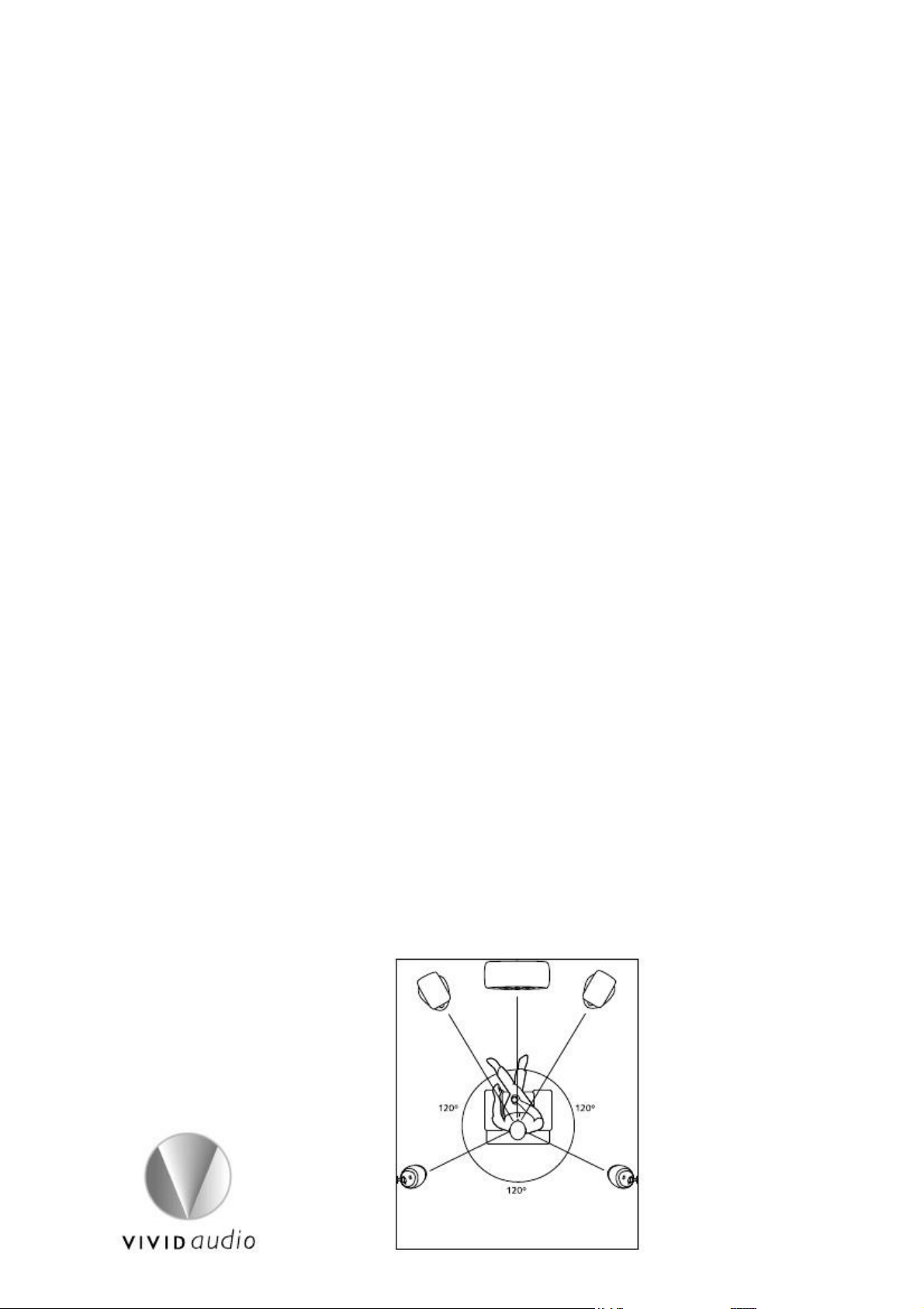
When using two surround speakers for the 5.1 rear position them at around 60˚
either side of a point directly to the rear of the listening position, fig.2. With uneven
rooms such as L-shapes, aim to have a general symmetry to their locations so the
angle of the speakers, as seen from the main listening position, is similar on both left
and right. Level differences due to the differing distances can be compensated for
during the set-up of the decoder.
Fig.2
4
Page 7

If the speakers are the wall mounted V1w, they should be mounted a good 50cm
above ear height, fig. 3, and, while mounting in the very corners of the room is not
to be recommended, try to get them as far away as reasonable. Again experiment
with the relative position of the seating, the screen and the speakers. You could
mount speakers on the back wall facing outward so the main sound is bounced off
the side walls to give a greater feeling of space.
Fig.3
With 6.1 and 7.1 installations, the side channels should be further forward, on a line
just behind the seating or around 80˚ either side of a point directly to the rear of the
listening position. A 6.1 system has a single rear speaker which should be directly
behind the listeners while a 7.1 system uses two rear speakers which should be placed
around 25˚ either side of the rear centre point, fig.4..
Fig.4
Installing V1 wall mount
V1w is designed for wall mounting through the use of a de-mountable ball and
socket arrangement. A hemispherical cage with cruciform cut-out is fitted to the
enclosure while the corresponding skeletal ball is fitted to a stem which can be
threaded directly onto an M8 wall anchor into a masonry wall, or bolted to a wall
plate which should be screwed to stud or timber walls using appropriate fixings.
5
Page 8
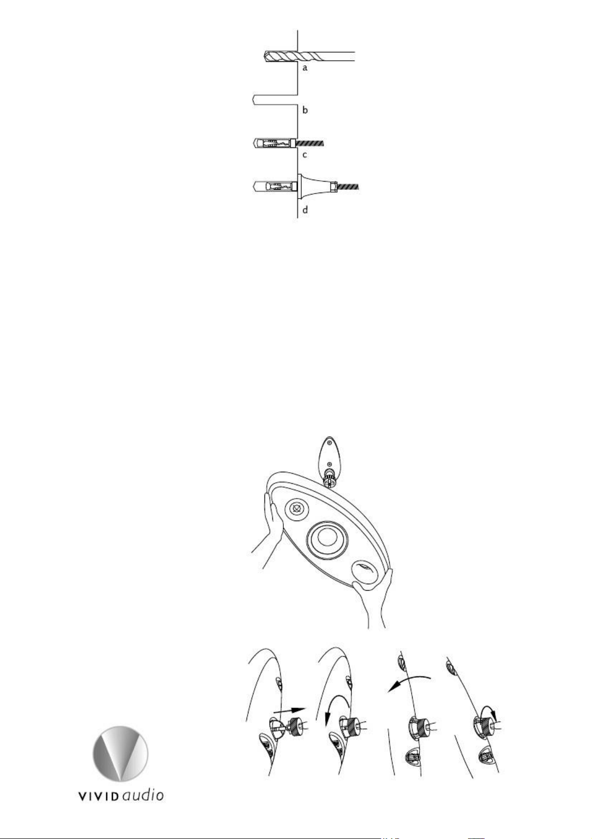
Fig.5
In the case of a masonry wall (fig. 5), first drill a 13mm hole to the depth of 60mm
using a suitable carbide tipped drill bit. Insert the wall anchor to the full depth and
hand wind the bracket stem onto the projecting M8 thread. Using a 13mm spanner,
tighten the stem until secure. Release the M8 Nylock nut on the end of the stem to
free the cross shaped ball and adjust its position a few degrees to the right or left
until the cross is square to the vertical. Tighten the lock nut.
With hollow walls you will need to use the wall plate. First mark the wall using the
plate as a guide and drill the appropriate holes. Then bolt the stem to the plate using
the M8 countersunk bolt. The assembly can then be fixed to the wall with a pair of
expanding or toggle bolts or, if fixing into the wooden studs, a pair of 5mm
countersunk woodscrews. Then align the cross–shaped ball to the vertical as before.
Now you can attach the loudspeaker.
Fig.6 a b c d
Fig.7 6 Facing the wall, turn the large knurled nut clockwise until it is right the way back
Page 9

against the end of the stem. Hold the loudspeaker at 45 degrees to the vertical (fig.6)
and offer up the cruciform hole in the socket to the corresponding cross on the end
of the stem and slide into place (fig.7a). Rotate the speaker until it is vertical (fig.7b)
then adjust the overall position to suit, fig.7c. The knurled nut should then be
tightened to lock the speaker into position, fig.7d.
Cabling and connections
We recommend that you make and secure all connections before turning on any
power to avoid short-circuiting the amplifiers.
In order to discourage folks from trying to stick speaker wires into mains outlets the
use of 4mm plugs is not encouraged which is a shame really because they tend to
be the most convenient. To this end the holes in the WBT connectors have small
rubber bungs fitted to make their use awkward but these can be removed.
To the sides of the WBT terminals are rectangular apertures into which you may
insert spade connectors. Vivid Audio speakers are supplied with these angled to the
opposite sides in the left and right speakers. This is just to help get the wires pointing
in the right direction but just use whichever suits your installation.
We don’t try to recommend any particular cable because it is an ever-changing field
but we would advise that you get something reasonably thick, say 2.5 mm2 for less
than 10m lengths and 4 mm for up to 20m.
K1, B1, C1 and V1.5 are provided with four terminals to permit the use of bi-wiring
or bi-amping shown in fig.8. The mid and high frequency crossover is connected
to the right hand pair of terminals (as view from the back) and the low frequency
to the other allowing the user to have separate wires feeding each section connected
to a single amplifier output, in the case of bi-wiring, or two independent amplifiers
in the case of bi-amping. This latter case even gives rise to the possibility of mixing
different types of amplifier for the two ranges but be careful to match the gain
and polarity of the two if you are to avoid messing up the basic frequency response
of the loudspeaker. If you are in any doubt about this you really should talk to
your dealer.
2
L.F.
Mid & H.F.
Fig.8
For many folks the use of extra wires will seem quite pointless in which case a single
pair of good quality conductors will be all you require and the two pairs of terminals
must be linked at the speaker using the links provided. In the accessories pack you
will find two 10cm lengths each of red and black wire each terminated with a 4mm
plug and spade. Link the hi-mid section to the low section as shown in Fig.10.
7
Page 10

Supplied non bi-wired links. Fig 9.
This arrangement will allow you to use amplifier leads terminated with either spade
connectors (as shown) or 4mm plugs.
L.F.
Mid & H.F.
Fig.10
Spikes
One of the innovative design features of certain Vivid Audio designs is the use of
reaction cancelling drivers and ports, the purpose of which is to cancel out any
reaction forces on the enclosure and hence the dependency of the overall acoustic
delivery on the way in which the loudspeaker is supported on the ground.
Nevertheless we do provide five M8 threaded holes in the bottom surface of the
base and five corresponding spikes to fit into these points if required for stability on
soft carpets. Some have also reported sonic benefits as a result.
We recommend that you have two fairly strong people available for this operation
particularly for our larger models. First lie the cabinet down on its side on a soft towel
and screw the five spikes all the way into their holes. Next, unscrew the two rear and
single front spike by two or thee turns and stand the speaker up. Ensure that the
speaker is vertical as seen from the front. Adjust the two rear spikes accordingly if
not. From the side you will have to verify that the base is horizontal since some of
the models have a slightly angled baffle. Don’t worry too much about this since it
is purely a visual issue so if it looks OK leave it there. If it needs a tweak then use the
front spike to make that adjustment. Once aligned tighten the lock nuts on these
three spikes. Then unscrew the two side spikes by hand until they touch the ground,
at which point it will become difficult to turn them further. Tighten the two
corresponding lock nuts and the operation is complete. Only hand tighten these
spikes - DO NOT USE A WRENCH.
Running in
8
Page 11

It is now fairly well accepted that, despite the protestations of the engineering teams
who design loudspeakers and who have difficulty accounting for it, there is a definite
period of time during which the sound of the equipment improves subtly. There are
definite and measurable changes which occur, particularly for the compliant
suspensions, as the various materials used soften up and gradually approach their
design values but it really does seem that some other improvements occur.
Some well respected authorities have even referred to it as a ‘learning’ phase.
There is also the far more earthly explanation that what is happening is that our
brain/ear combination is becoming accustomed to the new sound balance from the
loudspeakers. Certainly, the great clarity delivered by the Vivid Audio approach can
be a little disconcerting at first if you have been used to the sound of mid-range
cone break-up and the first reaction is that something is missing. Bit by bit you realise
that something is missing and you are really hearing through to the original recording
in a way that you never experienced before. This can in itself be rather revealing of
poorly edited work but then the original recording engineers may not have had the
benefit of monitoring on Vivid Audio loudspeakers so give them a break!
It is not really for us to get involved here with the philosophy or metaphysics of what
might be happening but suffice to say that you shouldn’t be too surprised if, after
owning you speakers for a few weeks, you really get very excited about what you’re
hearing.
Important
• The manufacturer warrants that these loudspeakers supplied will at the time
of delivery correspond to the description given by the manufacturer.
• The manufacturer declines all responsibility for damage resulting from improper,
incorrect or negligent use.
• Repairs must only be carried out by a service centre authorised by the manufacturer.
• All other warranties, conditions or terms relating to fitness for purpose, quality
or condition of the Goods, whether express or implied by statute or common law
or otherwise are excluded to the fullest extent.
9
Page 12

K1
K1 SPECIFICATION
Configuration :
3 & 1⁄2 way vented cabinet
Cabinet material :
Complex loaded carbon fibre filled polymer
Finish :
High gloss automotive
Drive units :
26mm metal dome hf unit
50mm metal dome mf unit
158mm metal coned lf unit (two pairs coupled)
Sensitivity :
89dB/1w @1m
Nominal Impedance (
6
):
Frequency range (hz) :
- 6dB points 35 – 44,000
Frequency response (hz) :
39 – 41,000 +/- 2dB on reference axis
Harmonic distortion (2nd and 3rd harmonics) :
< .0.5% over frequency range
Cross over frequencies (hz) :
100, 900, 4000
Power handling (music program) watts rms :
600
Loudspeaker dimensions (H, W, D cabinet, D base) mm :
1300, 280, 450, 488
Net mass (kg) :
56
Shipping dimensions (H, W, D) mm :
1420, 450, 560
Shipping mass (kg) :
70
10
Page 13

B1
B1 SPECIFICATION
Configuration :
3 & 1⁄2 way vented cabinet
Cabinet material :
Complex loaded carbon fibre filled polymer
Finish :
High gloss automotive
Drive units :
26mm metal dome hf unit
50mm metal dome mf unit
158mm metal coned lf unit (two of coupled)
Sensitivity :
89dB/1w @1m
Nominal Impedance (
4
):
Frequency range (hz) :
- 6dB points 35 – 44,000
Frequency response (hz) :
39 – 41,000 +/- 2dB on reference axis
Harmonic distortion (2nd and 3rd harmonics) :
< .0.5% over frequency range
Cross over frequencies (hz) :
100, 900, 4000
Power handling (music program) watts rms :
300
Loudspeaker dimensions (H, W, D cabinet, D base) mm :
1095, 265, 375, 420
Net mass (kg) :
38
Shipping dimensions (H, W, D) mm :
1220, 410, 510
Shipping mass (kg) :
50
11
Page 14

C1
C1 SPECIFICATION
Configuration :
3 way vented cabinet
Cabinet material :
Complex loaded carbon fibre filled polymer
Finish :
High gloss automotive
Drive units :
26mm metal dome hf unit
50mm metal dome mf unit
158mm metal coned lf unit (two of)
Sensitivity :
90dB/1w @1m
Nominal Impedance ( ) :
8
Frequency range (hz) :
- 6dB points 35 – 44,000
Frequency response (hz) :
39 – 41,000 +/- 2dB on reference axis
Harmonic distortion (2nd and 3rd harmonics) :
< .0.5% over frequency range
Cross over frequencies (hz) :
100, 900, 4000
Power handling (music program) watts rms :
300
Loudspeaker dimensions (H, W, D cabinet, D base) mm :
268, 755, 330
Net mass (kg) :
23
Shipping dimensions (H, W, D) mm :
370, 945, 450
Shipping mass (kg) :
35
C1 STAND
Material :
Complex loaded carbon fibre filled polymer
Finish :
High gloss automotive
Dimensions (H, W, D) :
440, 535, 380
Net mass (kg) :
13
Shipping dimensions (H, W, D) mm :
350, 448, 292
Shipping mass (kg) :
20
12
Page 15

V1.5
V1.5 SPECIFICATION
Configuration :
2 way vented cabinet
Cabinet material :
Complex loaded carbon fibre filled polymer
Finish :
High gloss automotive
Drive units :
26mm metal dome hf unit
158mm metal coned lf unit
Sensitivity :
89dB/1w @1m
Nominal Impedance (
8
Frequency range (hz) :
- 6dB points 40 - 28,000
Frequency response (hz) :
42 - 24,000 +/- 2dB on reference axis
Harmonic distortion (2nd and 3rd harmonics) :
< .0.5% over frequency range
Cross over frequency (hz) :
3000
Power handling (music program) watts rms :
150
Loudspeaker dimensions (H, W, D) mm :
1130, 255, 240
Net mass (kg) :
23
Shipping dimensions (H, W, D) mm :
1300, 430, 460
Shipping mass (kg) :
37 (unit)
):
13
Page 16

V1
V1s
V1 s,w & h SPECIFICATION
V1h
Configuration :
2 way vented cabinet
Cabinet material :
Complex loaded carbon fibre filled polymer
Finish :
High gloss automotive
Drive units :
26mm metal dome hf unit
158mm metal coned lf unit
Sensitivity :
89dB/1w @1m
Nominal Impedance (
8
Frequency range (hz) :
- 6dB points 42 - 28,000
Frequency response (hz) :
45 - 24,000 +/- 2dB on reference axis
Harmonic distortion (2nd and 3rd harmonics) :
< .0.5% over frequency range
Cross over frequency (hz) :
3000
Power handling (music program) watts rms :
150
Loudspeaker dimensions (H, W, D) mm :
635, 255, 195
Net mass (kg) :
V1s = 17 V1w = 13, V1h = 15
Shipping dimensions per pair (H, W, D) mm :
1420, 450, 560
Shipping mass (kg) :
V1s = 47 (pair), V1w = 39 (pair), V1h = 22 (unit)
):
The V1w suitable for both dry and masonry type
walling. As above without the moulded foot.
14
Page 17

Installation Notes:
_________________________________________________________________________
_________________________________________________________________________
_________________________________________________________________________
_________________________________________________________________________
_________________________________________________________________________
_________________________________________________________________________
_________________________________________________________________________
_________________________________________________________________________
_________________________________________________________________________
_________________________________
15
Page 18

Some loudspeaker history
1874 - Ernst W. Siemens was the first to describe the "dynamic" or moving-coil
transducer, with a circular coil of wire in a magnetic field and supported so that it
could move axially. He filed his U. S. patent application for a "magneto-electric
apparatus" for "obtaining the mechanical movement of an electrical coil from electrical
currents transmitted through it" on Jan. 20, 1874, and was granted patent No.
149,797 Apr. 14, 1874. However, he did not use his device for audible transmission,
as did Alexander G. Bell who patented the telephone in 1876. After Bell's patent was
granted, Siemens applied for German patent No. 2355, filed Dec. 14, 1877, for a
nonmagnetic parchment diaphragm as the sound radiator of a moving-coil transducer.
The diaphragm could take the form of a cone, with an exponentially flaring "morning
glory" trumpet form. This is the first patent for the loudspeaker horn that would be
used on most phonographs players in the acoustic era. His German patent was
granted July 30, 1878 and his British patent No. 4685 was granted Feb. 1, 1878.
Oliver Lodge
from Das Fotoarchiv
1898 - Oliver Lodge filed for British patent No. 9712 on Apr. 27, 1898, for an
improved loudspeaker with nonmagnetic spacers to keep the air gap between the
inner and outer poles of a moving coil transducer. This was the same year he applied
for a patent on his famous radio tuner. A model of his loudspeaker is in the British
Science Museum in South Kensington, and a photo was published in Wireless World
Dec. 21, 1927. This improvement was later claimed by Pridham and Jensen in the
Magnavox application for patent No. 1,448,279 filed Apr. 28, 1920, and granted
Mar. 13, 1923.
1901 - John Stroh first described the conical paper diaphragm that terminated at
the rim of the speaker in a section that was flat except for corrugations, filed for the
British patent No. 3393 on Feb. 16, 1901, granted Dec. 14, 1901.
1908 - Anton Pollak improved the moving-coil loudspeaker with a voice-coil centering
spider, filed for U.S. patent No. 939,625 on Aug. 7, 1908, granted Nov. 9, 1909.
1911 - Edwin S. Pridham and Peter L. Jensen in Napa, California, invented a moving-
coil loudspeaker they called the "Magnavox" that was used by Woodrow Wilson in
San Diego in 1919.
16
Page 19

Early Bell loudspeakers
1915 - Harold Arnold began program at Bell Labs to improve phonographic sound
recording. The first priority was the electronic amplifier using the new vacuum tube,
second was the microphone, and third was the loudspeaker that would improve the
"balanced armature" units developed for public address. After WWI, J. P. Maxfield
led this project that produced E. C. Wente's moving coil speaker by 1925, the
Orthophonic phonographic player by 1925, and Vitaphone talking motion pictures
by 1926.
1918 - Henry Egerton on 1918/01/08 filed patent for balanced-armature loudspeaker,
used in the Bell Labs No. 540AW speakers developed by N. H. Ricker Oct. 6, 1922,
that became the 540 commercial speaker by 1924; was based on the balanced
armature telephone patent of Thomas Watson granted Oct. 24, 1882, similar to
devices also developed by Siemens and Frank Capps.
1925 Grebe radio receiver and 1924 Western Electric 540 speaker (NMAH)
1921 - The Phonetron based on patent No. 1,847,935 filed Apr. 23, 1921, by C. L.
Farrand, was the first coil-driven direct-radiator loudspeaker to be sold in the U.S.
and was well-received, competing with the horns used by table radios
1923 - The Thorophone was a gooseneck loudspeaker with a voice-coil driver
1925 - The research paper of Chester W. Rice and Edward W. Kellogg at General
Electric was important in establishing the basic principle of the direct-radiator
loudspeaker with a small coil-driven mass-controlled diaphragm in a baffle with a
broad midfrequency range of uniform response. Edward Wente at Bell Labs had
independently discovered this same principle, filed patent No. 1,812,389 Apr. 1,
1925, granted June 30, 1931. The Rice-Kellogg paper also published an amplifier
design that was important in boosting the power transmitted to loudspeakers. In
1926, RCA used this design in the Radiola line of a.c. powered radios.
1925 - Victor Orthophonic acoustic phonograph player had a folded exponential
horn that was later used as model for the Klipsch speaker of the hi-fi era. Within a
year, the Orthophonic faced competition from all-electric phonographs with an
electromechanical pickup, vacuum-tube amplifier, and moving-coil loudspeaker, such
as the Brunswick Panatrope sold by the Brunswick-Balke-Collender Company.
17
Page 20

Vitaphone 555-W, from AT&T Archives
1926 - Vitaphone sound system for motion pictures used a new speaker developed
at Bell Labs. Wente and Thuras designed the Western Electric 555-W speaker driver
that was coupled with a horn having a 1-in. throat and a 40-sq. ft. mouth; it was
capable of 100-5000 hz freq. range with an efficiency of 25% (compared to 1%
today) needed due to low amp power of 10 watts. The power amps were 205-D.
Older loudspeakers were balanced armature type, but the newer 555-W speakers of
the Vitaphone were moving coil type.
1928 - Herman J. Fanger filed patent No. 1,895,071 on Sep. 25, 1928, granted Jan.
24, 1933, that described what came to be known as the coaxial speaker, composed
of a small high frequency horn with its own diaphragm nested inside or in front of
a large cone loudspeaker, based on the variable-area principle that made the center
cone light and stiff for high frequencies and the outer cone flexible and highly
damped for lower frequencies.
1929 - E. W. Kellogg filed patent No. 1,983,377 on September 17, 1929, granted
December 4, 1934, that described an electrostatic speaker composed of many small
sections able to radiate sound with out magnets or cones or baffles. This patent, as
well as the 1932 British patents of Hans Vogt, influenced Peter Walker to build the
Quad ESL flat panel speaker in 1957.
1929 - J. D. Seabert of Westinghouse developed a horn-type loudspeaker that directed
the sounds of human speech toward the audience better than cone speakers that
were intended for the over-all sound including music to fill the entire . These
"directional baffle" horns had an opening 3 ft. by 4 ft. and were different from small-
throat horns.
18
Page 21

Thuras bass-reflex patent
1930 - Albert L. Thuras filed patent No. 1,869,178 on Aug. 15, 1930, granted July
26, 1932, for the bass-reflex principle while working at Bell Labs. Early cabinets used
a passive baffle to direct sound to the front, allowing the back of the cabinet to be
open for the low sounds. The bass-reflex enclosure kept the low-frequency sounds
from being lost from the rear of the diaphragm.
1931 - Bell Labs developed the two-way loudspeaker, called "divided range" for the
demonstration by H. A. Frederick in December of vertically cut records. The high
frequencies were reproduced by a small horn with a frequency response of 3000-
13,000 hz, and the low frequencies by a 12-inch dynamic cone direct-radiator unit
with a frequency response within 5db from 50-10,000 hz. By 1933, a triple-range
speaker had been developed for the Constitution Hall demo in April, adding Western
Electric No. 555 driver units as the mid-range speaker. For the low frequency range
40-300 hz, a large moving coil-driven cone diaphragm in a large baffle expanding
from a 12-in throat to a 60-inch mouth over a total length of 10 ft. This 3-way system
was introduced in motion picture s as "Wide Range" reproduction.
1932 - RCA demonstrated a dual-range speaker of its own design for s, using three
6-inch cone diaphragms with aluminium voice coils in divergent directions, with a
response of 125-8000 hz, and 10-ft. horns 40-125 hz.
1933 - "Progress was such that a demonstration of the new system - called
"stereophonic" because of its ability to give a spatial sense corresponding to stereoscopic
vision - was given before the National Academy of Sciences and many invited guests
at Constitution Hall, Washington in the spring of 1933. Transmission was
Thuras theatre speaker 1933, from AT&T Archives
over wire lines from the Academy of Music in Philadelphia and three channels were
used with microphones respectively at left, centre and right of the orchestra stage
and loud speakers in similar positions in Constitution Hall." This transmission of music
"was carried out with special loud speakers developed for the purpose by Dr. Wente
and the late A. L. Thuras. The objectives in the design of these loudspeakers were
uniform response over the whole tonal range of the orchestra, an enhanced sound
power output capacity without noticeable non-linear distortion and uniform distribution
of the emitted sound at all frequencies throughout a wide solid angle.
19
Page 22

For the receiving unit and the multicellular horn which were developed for this
demonstration, Dr. Wente, jointly with the Bell Telephone Laboratories, was awarded
a gold plaque by the Academy of Motion Picture Arts and Sciences in 1936." (Bell
Labs, 1953)
1935 - Douglas Shearer and John Hilliard at MGM developed a standard speaker
system, starting with the Loews 5000-seat Capitol on Broadway. James Lansing and
Dr. John F. Blackburn of Cal Tech designed a 2-way speaker system; the high frequency
driver had a 3-inch aluminium diaphragm and throat size of 1.4 inches; the low
frequency baffled cone unit was 15 inches. ERPI provided speakers from Fletcher's
hi-fi experimental equipment to help design the speakers. The low frequency horn
used four 15-in. Lansing cone drivers and Lansing 284 drivers for multicell horns of
different sizes. The system was installed in 12 s for the opening of "Romeo and Juliet"
with Norma Shearer, sister of Douglas,
Aztec A-7 Voice of the , from Audio, Dec. 1961
then installed in all Loews s, then became the standard established by the Academy.
1940 - Paul W. Klipsch filed patent No. 2,310,243 on Feb. 5, 1940, granted Feb. 9,
1943, for the corner horn speaker.
1941 - Altec Lansing Corp. was formed when Altec bought Lansing; Altec Service
Corp. (from "all technical") had been formed in 1938 by M. Conroe and George
Carrington to manage ERPI installations after ERPI was dissolved. John Hilliard worked
at Altec Lansing in 1943 on magnetic airborne sub detection and in 1945 put on
the market the 2-way "Voice of the Theater" speaker system with improved horns
and magnet drivers. See Lansing Heritage for images and a detailed history.
Avery Fisher with 9-tube amp and coaxial speaker, from Fortune, Oct. 1946
1949 - W. E. Kock and F. K. Harvey at Bell Labs developed the acoustical lens, and
reported findings in 1949 JAES. These lenses are used in James B. Lansing theater
speakers and home hi-fi speakers
1953 - Arthur Janszen was granted patent No. 2,631,196 on March 10, 1953, for
an electrostatic high-frequency speaker
20
Page 23

1954 - Acoustic Research introduced the small AR-1 bookshelf loudspeaker that used
the acoustic suspension principle developed by company co-founder Edgar Villchur.
This was soon followed by the $89 AR-2 and by the AR-3 with improved domed
tweeters in 1958.
Walker's ESL, from Quad
1957 - Quad ESL marketed as the first full-range electrostatic loudspeaker, designed
by Peter Walker and David Williamson, based on Edward W. Kellogg's patent No.
1,983,377 filed September 17, 1929 and granted December 4, 1934.
1974 - Earthquake premiered Nov. 15 in the Chinese in Hollywood with Universal
Picture's Sensurround process developed by W. O. Watson and Richard Stumpf at
Universal. Four large low-frequency horns were located behind the screen, two in
each corner. The Model W horn in each corner was 8 ft. long, 4 ft. wide, 4 ft. high.
The Model C horn in each corner was a modular unit 1 ft. wide and 5 ft. high. Two
additional horns were located on a platform in the rear of the . Each horn was driven
by a 1000-watt amplifier controlled by inaudible tones on a special optical control
track along with the normal 4-track magnetic soundtrack of the 35mm Panavision
filmstrip.
1994 Sees the introduction of what was quite possibly the world’s least coloured
loudspeaker system – the Nautilus. Conceived and designed by Laurence Dickie the
loudspeaker has been highly acclaimed for over a decade and has a pride of place
in the Millennium Dome in London. Ten years later Laurence had honed these
technologies from Nautilus to new heights for a range of products from Vivid Audio,
to similar levels of acclaim and excitement from the world’s specialist press.
21
Page 24

To quote from Laurence’s Vivid Audio Ethos “Through aeons of evolution, the hearing
of animals like ourselves has developed an incredibly high sensitivity to resonance
and reflection as a matter of survival. Much crucial information can be deduced
about the surrounding environment and the presence of imminent danger by listening
for subtle changes in these effects.
At Vivid Audio, we believe that the subjective transparency of a loudspeaker system
is closely related the reduction of these two aberrations and have made every effort
to keep them to a minimum.
Each driver is designed to be pistonic within their working bandwidth with resonant
break-up occurring well above the range of audibility or at a frequency at least five
times that of the upper band limit. At the rear of the diaphragm, any cavities which
might lead to in-band resonances have been comprehensively vented or coupled to
matched absorbers, both actions which completely remove them.
Reflected energy from the rearward wave-front is also controlled by minimising the
area of any obstruction, such as the struts of the low frequency driver chassis or the
dome driver pole pieces, and ensuring that the wave then passes through an adequate
volume of absorbent material before meeting any boundaries.
A similar attention to detail is applied to the external surface which dictates that it
be free of any sharp features which might give rise to distinct reflections. The gently
swept spline curve, which defines the cabinet shape, ensures that the emerging
wave-front encounters no perturbation. All aspects of the enclosure design were
created using solid modelling to produce the seamless curves and precision features.
Such a smooth form and compact enclosure results in an extremely wide mid-band
dispersion which gradually narrows with ascending frequency. This natural sounding
polar performance integrates with a wide variety of listening environments to give
a gently falling power response which quality is widely acclaimed as being highly
desirable. Having a well-controlled off-axis response also widens the usable listening
area to include much of the room.
22
Page 25

Radial magnet technology permits the mounting of drivers with a minimal separation
ensuring the widest vertical beam at crossover while also having an intrinsically low
stray magnetic field which allows placement close to CRT monitors.
Having such a flowing line, the natural choice of enclosure material is a moulded
polymer. We selected a synthetic resin filled with a blend of graded mineral particles
and medium length carbon fibres. The moulds were cast from patterns cut from
solid using multi-axis mills driven directly from the 3D models created in the design
process.
The doubly curved form of the cabinet walls possesses a high degree of intrinsic
rigidity further enhanced by moulded lateral bracing which two factors ensure that
the resonant modes are sufficiently high in frequency. Direct mechanical excitation
of the enclosure is, in any case, avoided by rigorous use of compliant mounts for
every driver and reaction cancelling between the two low frequency drivers which
ensures that there is no net movement of the chassis below 100Hz. Reaction cancelling
is further applied to the design of the low frequency venting where a pair of ovoid
ports, with streamlined profile to minimise air turbulence, are positioned on the front
and back of the cabinet. The result is an extremely stable low frequency performance
with a rather novel appearance.
* Many of the above technologies are patented and are protected by international
law. Perceived infringements will be actively pursued.
VIVID AUDIO (PTY) LTD., P. O. BOX 343, KLOOF, 3640 KWAZULU NATAL, SOUTH
AFRICA
Telephone: +27 31 705 4168, Facsimile: +27 31 705 4167
VIVID AUDIO and the VIVID AUDIO logo are registered trade marks.
Patents exist on D26,D50 and C125 drivers.
All VIVID AUDIO products are in conformity with the EMC directive and the low
voltage directive.
Availability of models may vary from country to country.
Please visit our web site for the details of your nearest authorised dealer and to learn
more about us and our technology.
VIVID AUDIO reserves the right to change the design and or specifications of VIVID
AUDIO products without prior notice.
© 2003/4/5/6/7 VIVID AUDIO (PTY) Ltd. All rights
23
 Loading...