

Vive Comfort TP-S-955CR Installation Manual
Installation Manual
Thermostat Application Guide
Description
Gas or Oil Heat
Electric Furnace
Heat Pump (No Aux. or Emergency Heat)
Heat Pump (With Aux. or Emergency Heat)
Multi-Stage Systems
Heat Only Systems
Cool Only Systems
Millivolt
Yes
Yes
Yes
Yes
Yes
Yes
Power Type
Battery Power
Hardwire (Common Wire)
Hardwire (Common Wire) with
Battery Backup
Table of Contents
Installation Tips
Thermostat Quick Reference
Private Label Badge
Wiring
Wiring Diagrams
Technician Setup Menu
Programming
Features
Remote Sensor Operation
Specications
Page
A trained, experienced
technician must install this
product.
Carefully read these
instructions. You could damage
this product or cause a
hazardous condition if you fail
to follow these instructions.
Una version en español de este
manual se puede descargar en
la pagina web de la compañia.
Rev. 1802
U.S. Registered Trademark. Patents pending
Copyright 2018 All Rights Reserved.
5-7
8
13-18
1
2-4
Yes
Yes
21-28
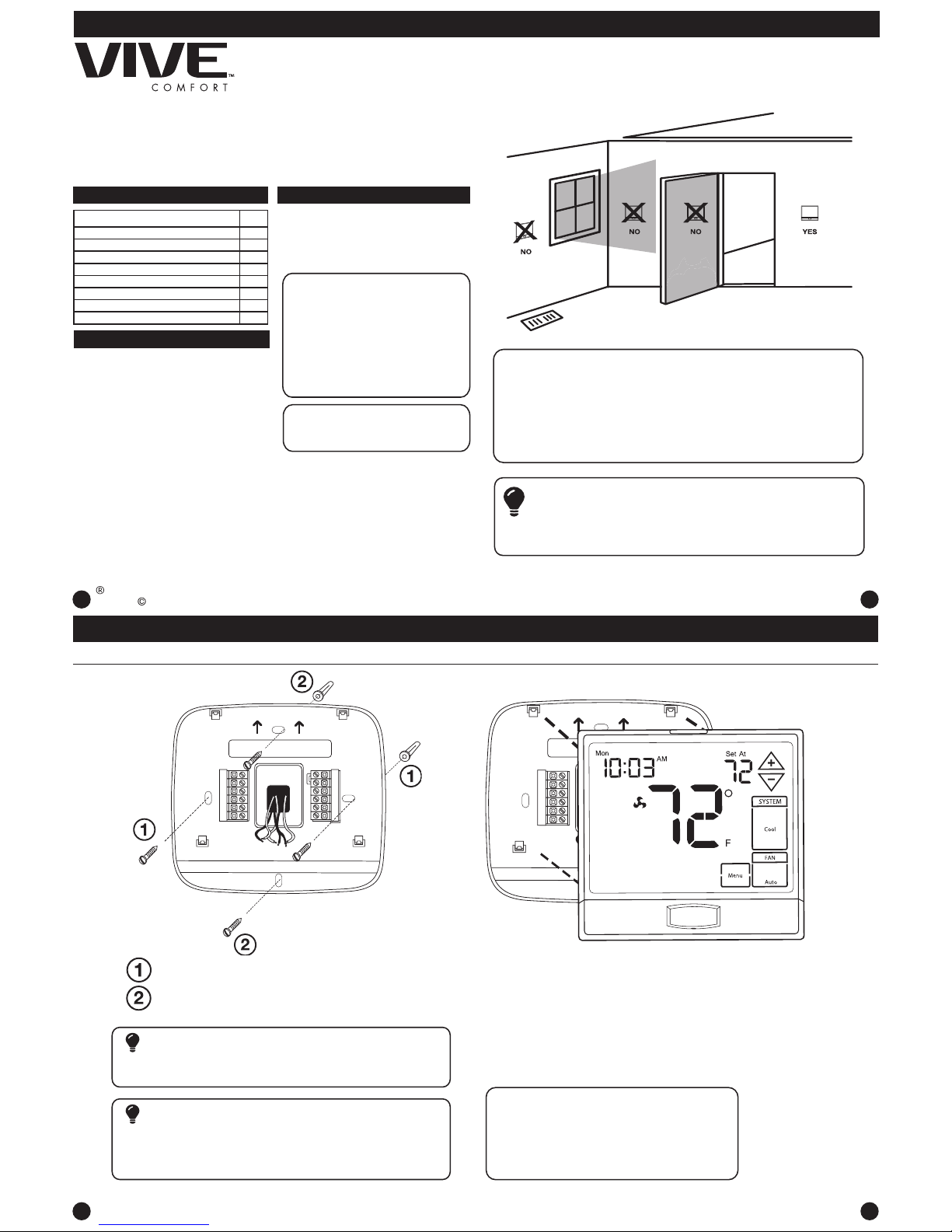
Mount Thermostat
Align the 4 tabs on the subbase with
corresponding slots on the back of the
thermostat, then push gently until the
thermostat snaps in place.
Installation Tips
2
Note: To ensure a solid t between the
thermostat and the subbase:
1. Mount subbase to a at wall
2. Use screws provided
3. Drywall anchors should be ush with the wall
4. Wires should be pushed into the wall
Installation Tips
The thermostat should be installed approximately 4 to 5 feet above the
oor. Select an area with average temperature and good air circulation.
• Close to hot or cold air ducts
• That are in direct sunlight
• With an outside wall behind the thermostat
• In areas that do not require conditioning
• Where there are dead spots or drafts (in corners or behind doors)
• Where there might be concealed chimneys or pipes
Wall Locations
Pick an installation location that is easy for the user to access. The temperature
of the location should be representative of the building.
Installation Tip
Do not install thermostat in these locations:
3
4
Installation Tips
30
Vertical Mount
Horizontal Mount
For horizontal mount put one screw on
the left and one screw on the right.
All of our products are mercury free. However, if the product you are
replacing contains mercury, dispose of it properly. Your local waste
management authority can give you instructions on recycling and
proper disposal.
Mercury Notice
Failure to disconnect the power before beginning to install this product
can cause electrical shock or equipment damage.
Installation Tip: Electrical Hazard
For vertical mount put one screw on
the top and one screw on the bottom.
Subbase Installation
11-12
9-10
P.O. Box 3377
Springeld, MO 65808-3377
31
29
Vive Comfort
Toll Free : 888-776-1427
Web: www.vivecomfort.com
Hours of Operation: M-F 9AM - 6PM Eastern
TP-S-955CR
Terminal Designations
This thermostat is shipped from the factory to operate a conventional heating
and cooling system. This thermostat may also be congured for a heat pump
system. See the “heat pump” conguration step on page 17 of this manual to
congure the thermostat for heat pump applications.
WiringWiring
Caution:
Electrical Hazard
All components of the control
system and the thermostat
installation must conform to
Class II circuits per the NEC Code.
Warning:
Do not overtighten terminal
block screws, as this can
damage the terminal block.
A damaged terminal block
can keep the thermostat
from tting on the subbase
correctly or cause system
operation issues.
Installation Tip
Max Torque = 6in-lbs.
Wiring
If you are replacing a thermostat,
make note of the terminal
connections on the thermostat that
is being replaced. In some cases
the wiring connections will not be
color coded. For example, the
green wire may not be connected
to the G terminal.
Loosen the terminal block screws.
Insert wires then retighten the
terminal block screws.
Place nonammable insulation into
the wall opening to prevent drafts.
1.
2.
3.
Wiring Tips
C Terminal
The C (common wire) terminal does
not have to be connected when the
thermostat is powered by batteries.
Wire Specications
Use shielded or non-shielded 18-22
gauge thermostat wire.
Failure to disconnect the power
before beginning to install this
product can cause electrical shock
or equipment damage.
Note:
In many heat pump systems with
no emergency heat relay, a jumper
can be installed between E and
W2 to turn thermostat into a single
stage control for Emergency Heat
Operation.
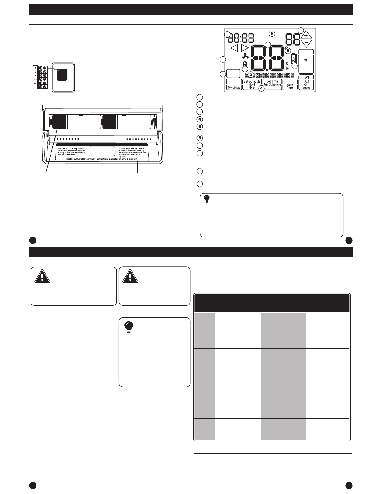
Thermostat Quick Reference
The low battery indicator is displayed when the AA battery power is low. If the user
fails to replace the battery within 21 days, the screen will only show the low battery
indicator but maintain all functionality. If the user fails to replace the batteries after
an additional 21 days (days 22-42 since rst “low battery” display) the setpoints will
change to 55˚F (Heating) and 85˚F (Cooling). If the user adjusts the setpoint away from
either of these, it will hold for 4 hours then return to either 55˚F or 85˚F. After day 63
the batteries must be replaced immediately to avoid freezing or overheating because
the thermostat will shut the unit o until the batteries are changed.
Important
Indicates the current room temperature
Time and day of the week
System Operation Indicators: HEAT ON, COOL ON and stages are shown
when these systems are running. NOTE: The compressor delay feature is
active if these icons are ashing. The compressor will not turn on until the 5
minute delay has elapsed.
Setpoint: Displays the user selectable setpoint temperature
HOLD is displayed when thermostat program is permanently overriden.
Low Battery Indicator: Replace batteries when this indicator is shown.
Program Menu Options: Show dierent options during programming.
Time Periods - Shows the 4 time Periods for Residential. 2 or 4 Commercial
time periods Occupied/Unoccupied are shown in this text eld.
Getting to know your thermostat
Thermostat Quick Reference
5
6
9
10
Battery Installation
Battery installation is recommended even if the thermostat is
hardwired (C terminal connected). When the thermostat is hardwired
and batteries are installed, the thermostat will activate a compressor
delay of 5 minutes when it detects a power outage from the hardwired
power supply.
Important:
High quality alkaline batteries are recommended.
Rechargeable batteries or low quality batteries
do not guarantee a 1-year life span.
Insert 2 AA Alkaline batteries
(included). High quality alkaline
batteries are recommended.
Simple operating instructions
are found on the back of the
battery door.
Clean Display: Will disable screen for 30 seconds to allow cleaning. A press
and hold of clean also will reset lter change and other reminders.
Keypad Lockout Icon
10
Clean
Display
Technician
Setup
Em. Heat
Cool
Heat
Auto
SYSTEM
HEAT ON
STAGE
1 2 3 4
COOL ON
Mon Tue Wed Thu Fri Sat Sun
AM
PM
Set At
WAKE
LEAVE
RETURN
SLEEP
HOLD
9
8
7
3
2
1
1
2
3
7
8
9
10
Outdoor temperature sensor, Indoor temperature sensors, and Slab sensor
wiring diagrams are located in the sensor manuals. See page 18 in tech setup.
Note:
Terminal
2 Heat 2 Cool
Conventional
System
2 Heat 2 Cool
Heat Pump
System
3 Heat 2 Cool
Heat Pump
System
RC
RH
C
B
O
G
W/E
Y
Y2
W2
Transformer power
(cooling)
Transformer power
(heating)
Transformer common
Energized in heating
Energized in cooling
Fan relay
First stage of heat
First stage of cool
Second stage of cool
Second stage of heat
Transformer power
(cooling)
Transformer power
(heating)
Transformer common
Heat pump changeover
valve energized in heating
Fan relay
First stage of
emergency heat
First stage of heat & cool
Second stage of cool
Auxiliary heat relay,
second stage of heat
Heat pump changeover
valve energized in cooling
Transformer power
(cooling)
Transformer power
(heating)
Transformer common
Heat pump changeover
valve energized in heating
Fan relay
First stage of
emergency heat
First stage of heat & cool
Second stage of cool
& second stage of heat
Auxiliary heat relay,
third stage of heat
Heat pump changeover
valve energized in cooling
S1/S2
Remote Sensor Remote Sensor Remote Sensor
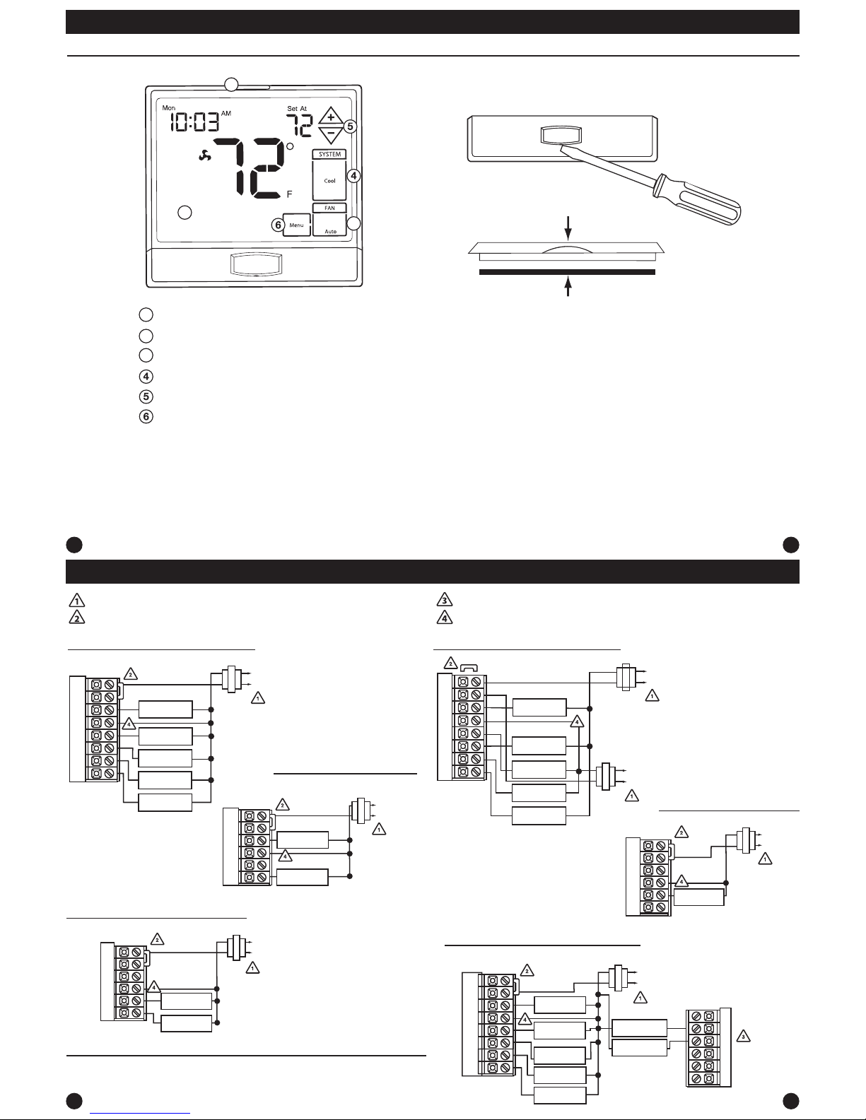
Getting to know your thermostat
Glow in the dark light button
Fan Key
System Key
Setpoint buttons
Menu button
LCD Display
Gently slide a screwdriver into the
bottom edge of the badge. Gently
turn the screwdriver counter
clockwise. The badge is held on by
a magnet in the well of the battery
door. The badge should pry o easily.
DO NOT USE FORCE.
About The Badge
All of our thermostats use the same universal magnetic badge. Visit the
company website to learn more about our free private label program.
Private Label BadgeThermostat Quick Reference
7
8
11
12
Wiring Diagrams Wiring Diagrams
Typical 2H/2C System: 1 Transformer Typical 2H/2C System: 2 Transformer
Typical 3H/2C or 2H/1C Heat Pump System
Typical Heat-Only System
Typical Heat Only System With Fan
Typical Cool-Only System
HEAT RELAY
RC
RH
Y
C
W/E
G
C
R
L2
L1(HOT)
FAN RELAY
HEAT RELAY
RC
RH
Y
C
W/E
G
C
R
L2
L1(HOT)
FAN RELAY
COMPRESSOR
RELAY
C
R
L2
L1(HOT)
RC
RH
Y
C
G
Power supply
Factory-installed jumper. Remove only when installing on 2-transformer systems
Use either O or B terminals for changeover valve
Optional 24 VAC common connection when thermostat is used in battery power mode
W/E
RC
RH
Y
C
W/E
G
W2
Y2
COMPRESSOR
RELAY
FAN RELAY
AUXILIARY
HEAT RELAY
COMPRESSOR
RELAY 2
COOL CHANGE
OVER VALVE
HEAT CHANGE
OVER VALVE
C
R
L2
L1(HOT)
REMOVE JUMPER
RC
RH
Y
C
W/E
G
W2
Y2
C
R
L2
L1(HOT)
C
R
L2
L1(HOT)
COMPRESSOR
RELAY
HEAT RELAY
FAN RELAY
HEAT RELAY 2
COMPRESSOR
RELAY 2
RC
RH
Y
C
W/E
G
W2
Y2
COMPRESSOR
RELAY
FAN RELAY
HEAT RELAY 2
COMPRESSOR
RELAY 2
HEAT RELAY
C
R
L2
L1(HOT)
O
B
EMERGENCY
HEAT RELAY
Magnet in door
Use the bevel on lower ridge
3
2
1
1
2
3
Note:
In many systems with no emergency heat relay a jumper can be installed
between W/E and W2.
 Loading...