

Vive Comfort TP-S-855i Installation Manual
Installation Manual
Thermostat Application Guide
Description
Gas or Oil Heat
Electric Furnace
Heat Pump (No Aux. or Emergency Heat)
Heat Pump (With Aux. or Emergency Heat)
Multi-Stage Systems
Heat Only Systems
Cool Only Systems
Millivolt
Yes
Yes
Yes
Yes
Yes
No
Power Type
Hardwire - 24 VAC
Common Wire
Table of Contents
Installation Tips
Thermostat Quick Reference
Private Label Badge
Wiring
Wiring Diagrams
Technician Setup Menu
WIFI Tech Setup
Programming
Features
Specications
Page
A trained, experienced
technician must install this
product.
Carefully read these
instructions. You could damage
this product or cause a
hazardous condition if you fail
to follow these instructions.
Una version en español de este
manual se puede descargar en
la pagina web de la compañia.
Rev. 1821
U.S. Registered Trademark. Patents pending
Copyright 2018 All Rights Reserved.
5-7
8
13-19
2-4
Yes
Yes
20
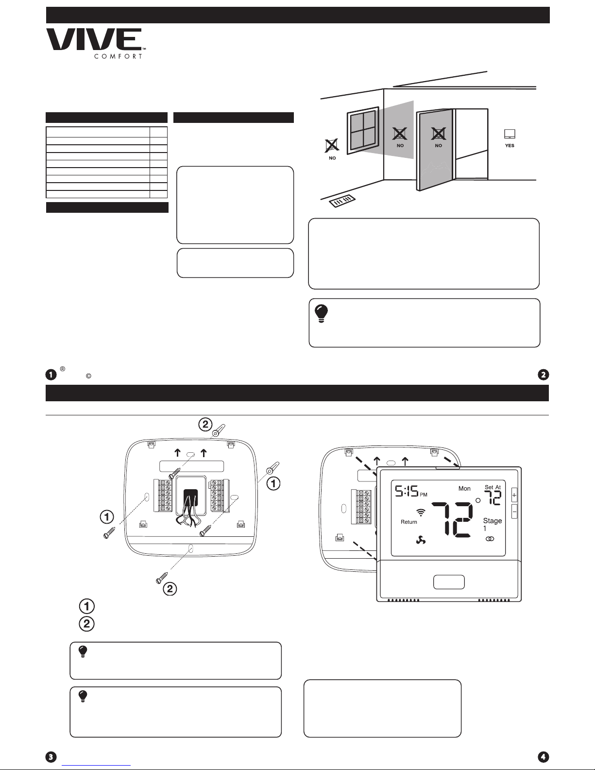
Mount Thermostat
Align the 4 tabs on the subbase with
corresponding slots on the back of the
thermostat, then push gently until the
thermostat snaps in place.
Installation Tips
Note: To ensure a solid t between the
thermostat and the subbase:
1. Mount subbase to a at wall
2. Use screws provided
3. Drywall anchors should be ush with the wall
4. Wires should be pushed into the wall
Installation Tips
The thermostat should be installed approximately 4 to 5 feet above the
oor. Select an area with average temperature and good air circulation.
• Close to hot or cold air ducts
• That are in direct sunlight
• With an outside wall behind the thermostat
• In areas that do not require conditioning
• Where there are dead spots or drafts (in corners or behind doors)
• Where there might be concealed chimneys or pipes
Wall Locations
Pick an installation location that is easy for the user to access. The temperature
of the location should be representative of the building.
Installation Tip
Do not install thermostat in these locations:
Installation Tips
21-28
31
Vertical Mount
Horizontal Mount
For horizontal mount put one screw on
the left and one screw on the right.
All of our products are mercury free. However, if the product you are
replacing contains mercury, dispose of it properly. Your local waste
management authority can give you instructions on recycling and
proper disposal.
Mercury Notice
Failure to disconnect the power before beginning to install this product
can cause electrical shock or equipment damage.
Installation Tip: Electrical Hazard
For vertical mount put one screw on
the top and one screw on the bottom.
Subbase Installation
11-12
9-10
29-30
Vive Comfort
Toll Free : 888-776-1427
Web: www.vivecomfort.com
Hours of Operation: M-F 9AM - 6PM Eastern
TP-S-855i
MENU AUTO HEAT
P.O. Box 3377
Springeld, MO 65804

Wiring Chart
For all systems, the following terminals are wired according to whether you
have a single or dual transformer system as shown:
WiringWiring
Caution:
Electrical Hazard
All components of the control
system and the thermostat
installation must conform to
Class II circuits per the NEC Code.
Warning:
Do not overtighten terminal
block screws, as this can
damage the terminal block.
A damaged terminal block
can keep the thermostat
from tting on the subbase
correctly or cause system
operation issues.
Installation Tip
Max Torque = 6in-lbs.
Wiring
If you are replacing a thermostat,
make note of the terminal
connections on the thermostat that
is being replaced. In some cases
the wiring connections will not be
color coded. For example, the
green wire may not be connected
to the G terminal.
Loosen the terminal block screws.
Insert wires then retighten the
terminal block screws.
Place nonammable insulation into
the wall opening to prevent drafts.
1.
2.
3.
Wiring Tips
C Terminal
This thermostat requires a 24V
common wire to the C terminal.
Wire Specications
Use shielded or non-shielded 18-22
gauge thermostat wire.
Failure to disconnect the power
before beginning to install this
product can cause electrical shock
or equipment damage.
Note:
In many heat pump systems with
no emergency heat relay, a jumper
can be installed between E and
W2 to turn thermostat into a single
stage control for Emergency Heat
Operation.
Thermostat Quick Reference
Indicates the current room temperature
Time and day of the week
Staging Indicators: Indicates stages of heat or cool running. The compres-
sor delay feature is active if these are ashing.
Setpoint: Displays the user selectable setpoint temperature.
Hold: Is displayed when the thermostat program is permanently overridden.
WIFI Connection Indicator
1
2
3
7
8
9
WIFI Signal Strength
Button Options
Program Time Periods - Residential: Uses 4 time periods - WAKE, RETURN,
LEAVE & SLEEP. Commercial uses 2 time periods - OCCUPIED, UNOCCUPIED.
7
3
2
8
9
Getting to know your thermostat
Thermostat Quick Reference
Lockout Indicator
Fan Indicator
FAILURE TO REMOVE PROVIDED JUMPER ON DUAL TRANSFORMER INSTALLATIONS
COULD CAUSE SEVER DAMAGE TO HVAC SYSTEMS
The following terminals on the thermostat wallplate are wired
according to the type of HVAC system connected to and how the
thermostat is congured.
Devices such as a oat switch that mechanically break circuits should
be installed so that they break the control wire (Y) not the power (R).
Interrupting the power circuit will shut o power to the thermostat
completely and not allow it to operate.
Note
Y1 Y2 W/E W2 O B
Getting to know your thermostat
1
2
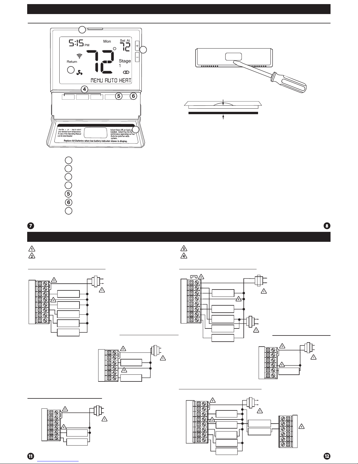
Getting to know your thermostat
Glow in the dark light button
Temperature Setpoint buttons
Program buttons
Fan button
System button
LCD Display
1
2
3
7
Button access door
Gently slide a screwdriver into the
bottom edge of the badge. Gently turn
the screwdriver counter clockwise. The
badge is held on by a magnet in the well
of the battery door. The badge should pry
o easily. DO NOT USE FORCE.
About The Badge
All of our thermostats use the same universal magnetic badge. Visit the
company website to learn more about our free private label program.
Private Label BadgeThermostat Quick Reference
Wiring Diagrams Wiring Diagrams
Typical 2H/2C System: 1 Transformer Typical 2H/2C System: 2 Transformer
Typical 3H/2C or 2H/1C Heat Pump System
Typical Heat-Only System
Typical Heat Only System With Fan
Typical Cool-Only System
HEAT RELAY
RC
RH
Y
C
W/E
G
C
R
L2
L1(HOT)
FAN RELAY
HEAT RELAY
RC
RH
Y
C
W/E
G
C
R
L2
L1(HOT)
FAN RELAY
COMPRESSOR
RELAY
C
R
L2
L1(HOT)
RC
RH
Y
C
G
Power supply
Factory-installed jumper. Remove only when installing on 2-transformer systems
Use either O or B terminals for changeover valve
A 24 VAC common connection is required with this thermostat.
W/E
RC
RH
Y
C
W/E
G
W2
Y2
COMPRESSOR
RELAY
FAN RELAY
AUXILIARY
HEAT RELAY
COMPRESSOR
RELAY 2
EMERGENCY
HEAT RELAY
COOL CHANGE
OVER VALVE
HEAT CHANGE
OVER VALVE
C
R
L2
L1(HOT)
REMOVE JUMPER
RC
RH
Y
C
W/E
G
W2
Y2
C
R
L2
L1(HOT)
C
R
L2
L1(HOT)
COMPRESSOR
RELAY
HEAT RELAY
FAN RELAY
HEAT RELAY 2
COMPRESSOR
RELAY 2
RC
RH
Y
C
W/E
G
W2
Y2
COMPRESSOR
RELAY
FAN RELAY
HEAT RELAY 2
COMPRESSOR
RELAY 2
HEAT RELAY
C
R
L2
L1(HOT)
O
B
4
Magnet in door
Use the bevel on lower ridge
1
2
3
7
 Loading...