

Vive Comfort TP-N-631W, TP-N-631 Installation Manual

Installation Manual
Thermostat Application Guide
Description
Gas or Oil Heat
Electric Furnace
Heat Pump (No Aux. or Emergency Heat)
Heat Pump (With Electric Aux.)
Multi-Stage Systems
Heat Only Systems - Floor or Wall Furnace
Cool Only Systems
Millivolt
Yes
Yes
Yes
Yes
No
No
Yes
Yes
Yes
Power Type
Battery Power
Hardwire (Common Wire)
Hardwire (Common Wire) with
Battery Backup
Table of Contents
Installation Tips
Thermostat Quick Reference
Base Module Tips
Wiring
Wiring Diagrams
Technician Setup
Swing Setting
Reestablishing
Communication
Specications
Page
A trained, experienced
technician must install this
product.
Carefully read these
instructions. You could damage
this product or cause a
hazardous condition if you fail
to follow these instructions.
Una version en español de este
manual se puede descargar en
la pagina web de la compañia.
Rev. 1821
Mount Thermostat
Align the 4 tabs on the subbase with
corresponding slots on the back of the
thermostat, then push gently until the
thermostat snaps in place.
Battery Installation
Battery installation is optional if thermostat is
hardwired (R and C terminal connected to 24V
power).
Important:
High quality alkaline batteries are recommended.
Rechargeable batteries or low quality batteries
do not guarantee a 1-year life span.
Insert 2 AA
Alkaline batteries
(included). High
quality alkaline
batteries are
recommended.
Installation Tips
4
5-6
7
8-10
11-12
2-3
Installation Tips Thermostat Quick Reference
Getting to know your thermostat
Fan Switch
System Switch
Setpoint Buttons
LCD
The low battery indicator is displayed when the
AA battery power is low. If the user fails to
replace the battery within 21 days, the screen
will only show the low battery indicator but
maintain all functionality. If the user fails to
replace the batteries after an additional 21 days
(days 22-42 since rst “low battery” display) the
setpoints will change to 55˚F (Heating) and 85˚F
(Cooling). If the user adjusts the setpoint away
from either of these, it will hold for 4 hours
then return to either 55˚F or 85˚F. After day 63
the batteries must be replaced immediately to
avoid freezing or overheating because the
thermostat will shut the unit o until the
batteries are changed.
Important
Removing The Private
Label Badge
Gently slide a screwdriver into the
bottom edge of the badge. Gently turn
the screwdriver counter clockwise. The
badge is held on by a magnet in the well
of the battery door. The badge should pry
o easily. DO NOT USE FORCE.
About The Badge
All of our thermostats use the same universal magnetic badge. Visit the
company website to learn more about our free private label program.
Subbase Installation
The thermostat should be installed approximately 4 to 5 feet above the
oor. Select an area with average temperature and good air circulation.
• Close to hot or cold air ducts
• That are in direct sunlight
• With an outside wall behind
the thermostat
• In areas that do not require
conditioning
• Where there are dead spots
or drafts
(in corners or behind doors)
• Where there might be
concealed chimneys or
pipes
Wall Locations
Vertical Mount
Horizontal Mount
For vertical mount put one screw on the top
and one screw on the bottom.
For horizontal mount put one screw on the
left and one screw on the right.
All of our products are mercury free.
However, if the product you are
replacing contains mercury, dispose of
it properly. Your local waste
management authority can give you
instructions on recycling and proper
disposal.
Pick an installation location that is easy for
the user to access. The temperature of the
location should be representative of the
building.
Installation Tip
Mercury Notice
Do not install
thermostat in locations:
Failure to disconnect the power before
beginning to install this product can
cause electrical shock or equipment
damage.
Installation Tip:
Electrical Hazard
U.S. Registered Trademark. Patents pending
Copyright 2018 All Rights Reserved.
Heat Pump (With Gas Aux.)
Emergency Heat
Conventional Single Stage Furnace
Geothermal
High and Low Fan Speed
No
No
Yes
Yes
+1 will appear in the
display when the
auxiliary heat is active.
Displays the
user selectable
setpoint
temperature.
System operation
indicators: On
will display when
the COOL or HEAT
is on.
Low Battery
Indicator:
Replace
batteries when
indicator is
shown.
Indicates the
current room
temperature.
88
13
14
15
Magnet in door
Use the bevel on lower ridge
88
LOW
HIGH
Located on the back of thermostat.
Vive Comfort
Toll Free : 888-776-1427
Web: www.vivecomfort.com
Hours of Operation: M-F 9AM - 6PM Eastern
TP-N-631W
LOW
HIGH
P.O. Box 3377
Springeld, MO 65804
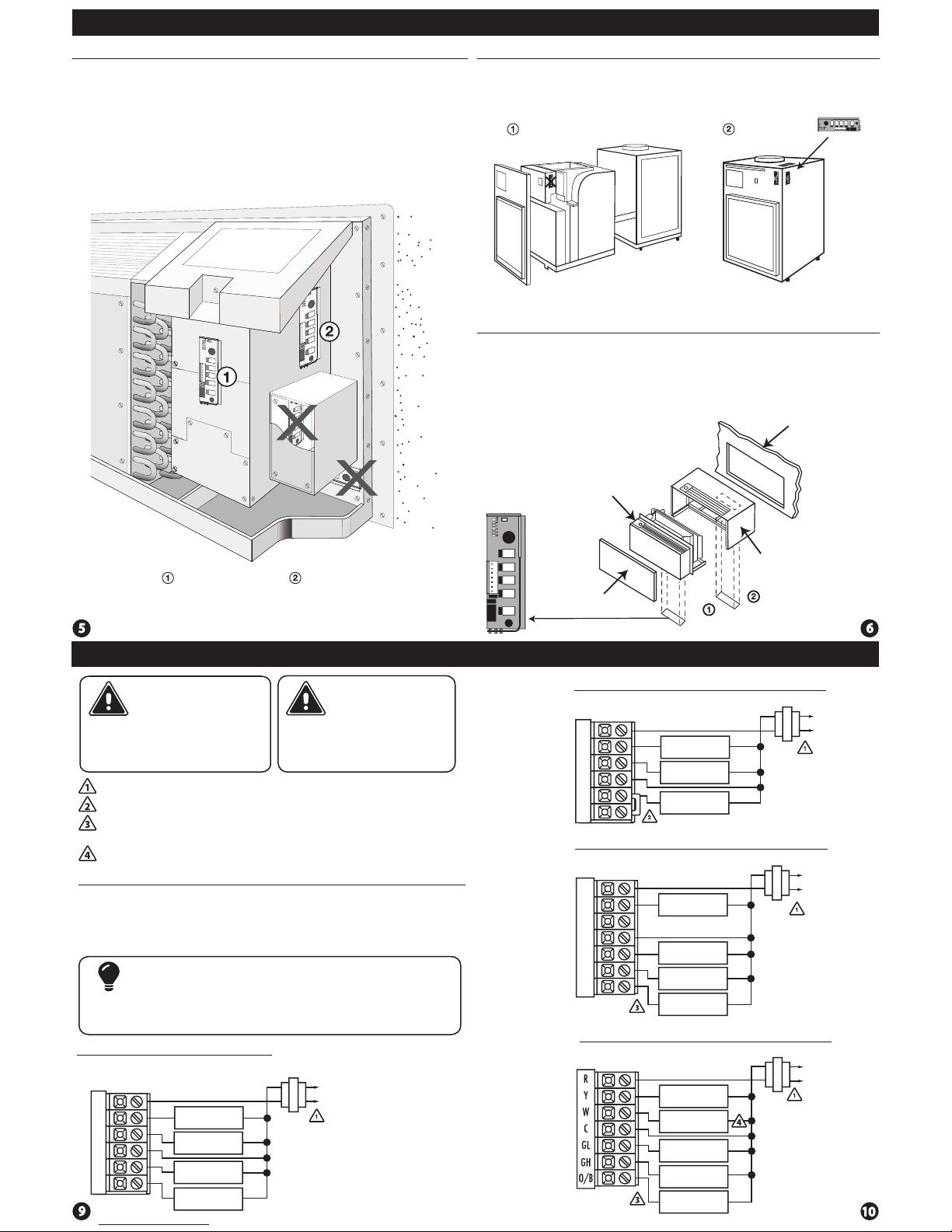
Base Module Tips
Base Module - PTAC Installation
Side Mount:
Inside PTAC
Housing
Front Mount:
Inside PTAC
Housing
Base Module Tips
Range between the thermostat and the base module is up to 100 feet
with no obstructions and up to 50 feet through standard building
materials. To optimize the range try placing the base module with no
metal between it and the thermostat.
The base module is designed to be mounted behind the front grille
of a packaged terminal air conditioner (PTAC). Refer to the PTAC
manufacturer’s manual for instruction to remove the front grille.
Check clearance to ensure the t of front grille after base module
installation. See below for a few location recommendations.
When Working With A Vertical Unit
1. Do not mount Module inside the cabinet of the unit, or in a
metal enclosure.
2. Mount on the outside of the unit to maximize wireless
communication.
When Working With A Metal Sleeve Cabinet, Room Cabinet,
or PTAC Cover
1. If cabinet has open bottom, mount the module just inside the
cabinet as close to the open bottom as possible without placing it in
danger of being bumped or touched by furnishings, vaccum, etc.
2. Another good module location would be on the underside of the
top of the cabinet or cover. Directly behind the open Louver/Grill.
Caution:
Electrical Hazard
All components of the control
system and the thermostat
installation must conform to
Class II circuits per the NEC Code.
Warning:
Failure to disconnect the power
before beginning to install this
product can cause electrical
shock or equipment damage.
Power supply
Jumper (not supplied) to connect GL and GH terminals.
Typical 1H/1C System: 2 Speed Fan
Wiring Tips
C Terminal
The C (common wire) terminal does
not have to be connected when the
thermostat is powered by batteries.
Wire Specications
Use shielded or non-shielded
18-22 gauge thermostat wire.
Wiring Diagrams Wiring Diagrams
Thermostat must be set to O and B to match the changeover valve, O is the
cool changeover valve, B is heat changeover valve.
The Aux Heat Relay is energized as the second stage of heat.
R
Y
W
C
GL
GH
COMPRESSOR
RELAY
HEAT RELAY
FAN LOW RELAY
FAN HIGH RELAY
C
R
L1
L2
Typical 1H/1C System: 1 Speed Fan
R
Y
W
C
GL
GH
HEAT RELAY
FAN RELAY
COMPRESSOR
RELAY
Typical 1H/1C Heat Pump System: 2 Speed Fan
R
Y
W
C
GL
GH
O/B
COMPRESSOR
RELAY
CHANGE OVER
VALVE
FAN LOW RELAY
FAN HIGH RELAY
C
R
L1
L2
C
R
L2
L1
Typical 2H/1C Heat Pump System: 2 Speed Fan
C
R
L2
L1
COMPRESSOR
RELAY
AUX HEAT
RELAY
FAN LOW RELAY
FAN HIGH RELAY
CHANGE OVER
VALVE
Most PTAC systems support two speed fan operation. In a single speed
fan PTAC system or conventional single speed fan system, a jumper
should be installed between GL and GH on the thermostat.
Note:
Front Panel
Chasis
Sleeve Cabinet
Rough-In
Wall Openin
g
 Loading...