

Page 1
HYDRAULIC
PATIENT LIFT
MOB1068
vivehealth.com
To see all FAQs
in one place,
visit vhealth.link/0vg
OWNER’S MANUAL
Page 2
HYDRAULIC PATIENT LIFT
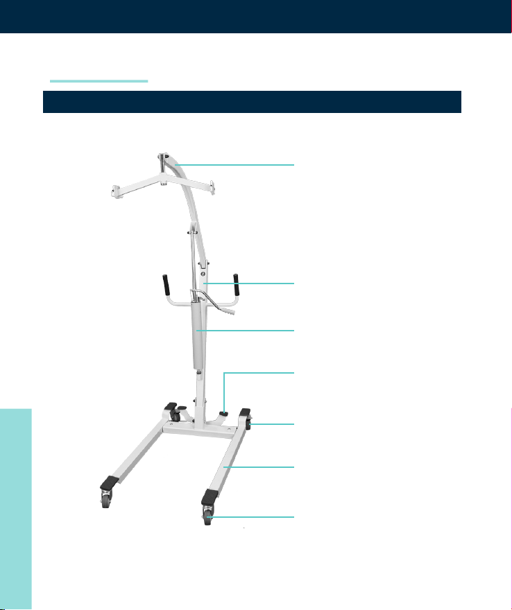
PARTS DESCRIPTION
Lifting Arm
Main Frame
Hydraulic Pump
Width Adjusting
Pedal
Castor
OWNER’S MANUAL
Base
Front Castor
Page 3
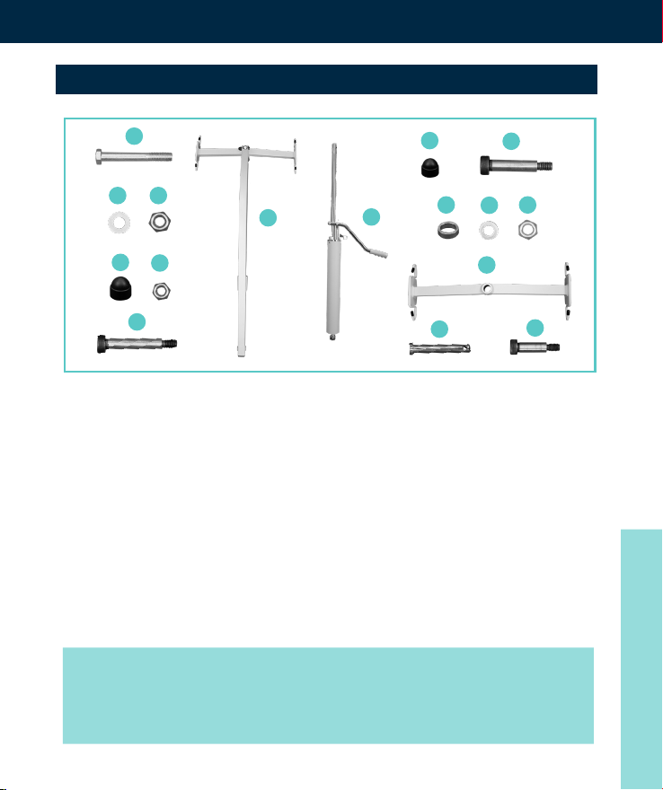
HARDWARE INCLUDED
MOB1068
A
B C
G
D
E
F
• Hexagon bolt M10x75 x2
(A)
• Washer x2 (B)
• Lock Nut x2 (C)
• Nut Cap x2 (D)
• Small Nut x3 (E)
• Hexagon bolt M10x70 (F)
• Lifting Arm(G)
• Hydraulic Pump (H)
I
H
K
O
J
L
M
N
P
• Small Nut Cap x3 (I)
• Hexagon bolt M10x60 (J)
• Spacer x2 (K)
• Small Washer x3 (L)
• Small Lock Nut x3 (M)
• Sling Holder (N)
• Sling Holder Support
Pipe (O)
• Hexagon bolt M10x55(P)
NOTE:
Some hardware is pre-installed onto the device. Sling
not included.
OWNER’S MANUAL
Page 4
ASSEMBLY INSTRUCTIONS
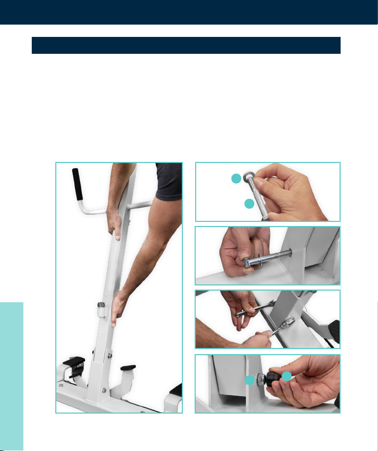
1. Place the Main Frame Arm and align the holes with
the Base. Fix (A) M10x75 hexagon bolt with (B) Washer
and insert it through both the holes on the base.
Attach the (C) nut and to the other end and tighten
down using your wrenches. Then place the nut cap (D)
on the nut.
OWNER’S MANUAL
1 2
A
B
3
4
5
C
D
Page 5
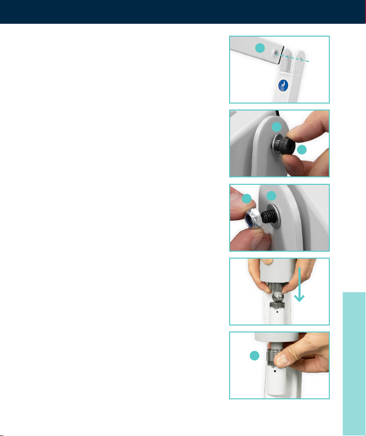
2. Insert the Lifting Arm (G) into the
upper groove of the frame. Make
sure the holes are in alignment
and then slip the Hexagon bolt
M10x70 (F) with a Small Washer
(L) through the hole. On the
opposite side attach another
Small Washer (L) and a Small
Lock Nut (M). Tighten down with
a wrench and an allen key, nally
and attach the Small Nut Cap (I).
There should be no movement of
the lifting arm.
3. Install the Hydraulic Pump by
rst putting the ball-end of the
hydraulic cylinder into main
frame. Secure it with the xed
Lock Nut (C) to lock the bolt
in place.
MOB1068
G
L
F
L
M
C
OWNER’S MANUAL
Page 6
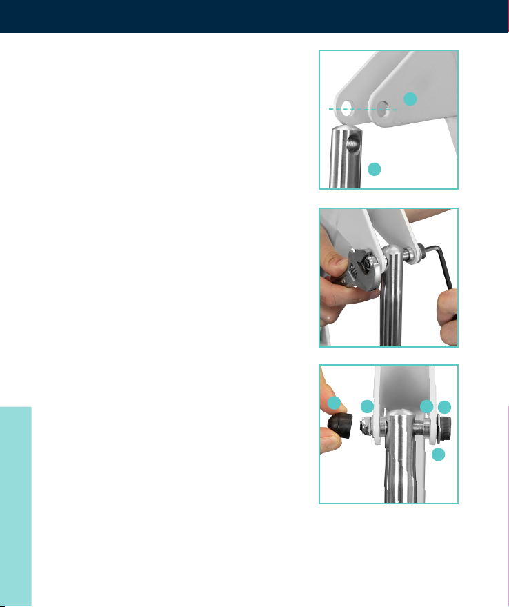
4. Finish the Installation of the
Hydraulic Pump (H) by attaching
the top part to the Lifting Arm
(G) by rst lining up the holes.
Insert a Small Washer (L) onto
the Hexagon bolt M10x60 (J) then
slide through the rst hole. On
the other side of the rst hole be
ready with a Spacer (K). Continue
on through the hole of the top
of the Hydraulic Pump. Then
on the other side of that add
another spacer, then continue
on through the last hole. On the
opposite side attach another
Small Washer (L) and a Small
Lock Nut (M). Tighten down with
a wrench and an allen key. Finally
and attach the Small Nut Cap (I).
When nished you should have a
space on each side of the
hydraulic pump pipe.
G
H
I
M
K
J
L
OWNER’S MANUAL
Page 7
MOB1068
N
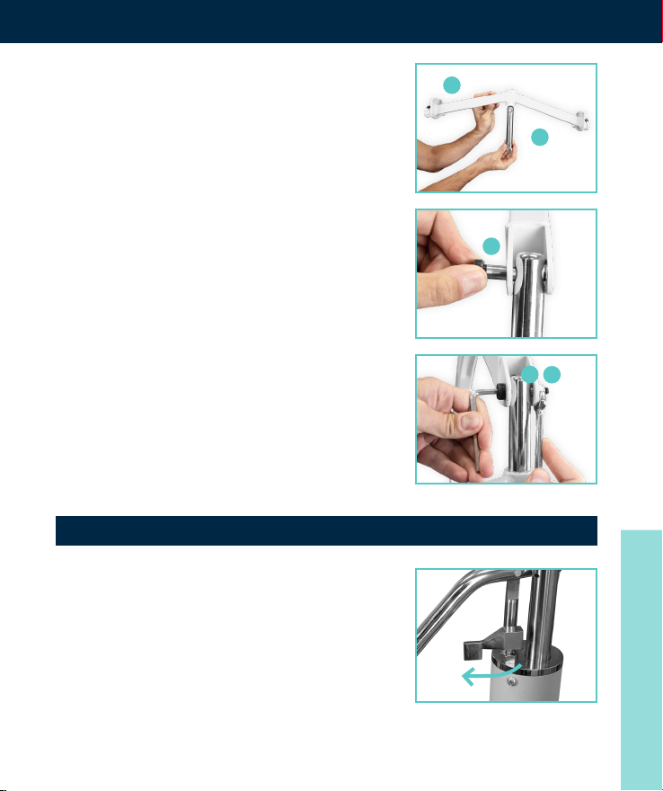
5. Insert (O) Sling Holder Pipe into
the (N) Sling Holder. Attach this
new piece to the Lifting Arm by
aligning the holes on the Lifting
Arm and the Sling Holder Pipe.
Use the (P) Hexagon bolt M10x55
to secure the two together along
with the Small Washer (L) and
a Small Lock Nut (M). Tighten
down with a wrench and an allen
key, nally and attach the Small
Nut Cap (I).
HYDRAULICS HANDLING PROCEDURE
Slide the valve switch Inwards
(towards the lift handle) to Lock the
downward ability of the lift.
O
P
L
M
OWNER’S MANUAL
Page 8
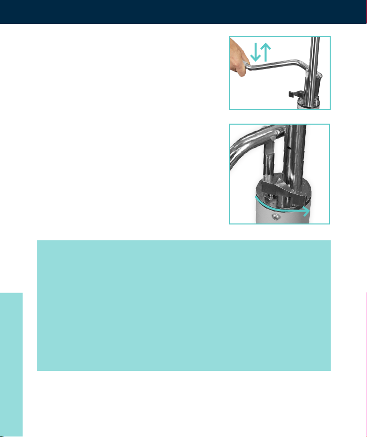
Operate the hydraulic handle up and
down to lift the patient.
Slide the valve switch outwards
(Away from the lift handle) and
the hydraulic cylinder will decline,
relying on the patient’s own weight.
When it declines to a
requested height, re-lock
the valve switch.
NOTE:
The amount you push the switch outward will affect
the speed of how fast the patient is lowered. Use
caution to gauge how much to move the switch
outward vs. how fast you want to lower the patient.
Never ip the switch all the way outward without
slowly testing your speeds as every patient’s speed is
different due to their weights.
OWNER’S MANUAL
Page 9
MOB1068
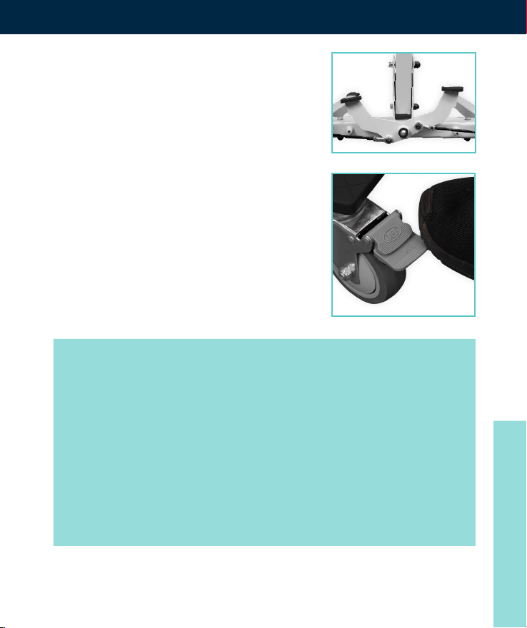
Base Width Adjustment:
The width of the base can be
adjusted by pedal. Press on the left
pedal for a wider base and the pedal
on the right for a more narrow base.
Lock and Unlock Rear Wheels:
The rear wheels can be locked. Use
your foot to lock and unlock the
rear wheels.
ATTENTION:
It is unnecessary to lock the rear wheels for most
ascent and descent movements. Only lock the wheels
when the lift moves and may cause personal injury.
WARNING:
Locking the real wheels of the lift may increase the
risk of tipping during the ascent and descent of
a patient.
OWNER’S MANUAL
Page 10

OPERATION OF PATIENT LIFT
Keep the lifting arm and patient’s body vertical. Make
sure the operation of the lift is correct each time.
WARNING:
An imbalance during ascent increases the risk of
tipping. Always use on at grounds.
Check and ensure the following items after nishing the
assembling process:
• All connections are properly locked and there are
no loose parts.
• The hydraulic cylinder rises properly after turning on the
valve switch and while operating the handle up
and down.
• The hydraulic cylinder descends properly with weight
loaded after turning off the valve switch.
• The 4 casters function properly.
CARE AND MAINTENANCE
• Washing with a household cleaning agent.
• Use a dried cloth with a diluted neutral detergent to
wipe any stains or grease.
• Lacquer thinner, gasoline, Kerosene, volatile solvents,
OWNER’S MANUAL
wax, sponges, and abrasive brushes are not permitted.
Page 11

TROUBLESHOOTING
Patient Lift Doesn’t Work Check if there is any
damage to the hydraulic
cylinder.
MAINTENANCE RECORD
Date Fault Cause Remark
MOB1068
OWNER’S MANUAL
Page 12

SPECIFICATIONS
Device Name Hydraulic Patient Lift
Model/type MOB1068
Product Size 47.25”×24.5” ×48.25”
Fork Range 24.5” - 31.5” adjustable
Lifting Range 31” (lowest), 68” (highest)
Maximum Capacity 400 lbs.
Net Weight 86 lbs.
WARNINGS
• Lift should only be operated by adults with proper
knowledge of how to handle a lift and properly position
a lift sling. Consult with a care giver before attempting to
use this device with no prior knowledge of how it works.
• Maximum User Weight: 400lbs
NOTE:
Make sure the sling you purchase can hold equal to or
more weight.
• Always gauge the speed of the hydraulic pumps
lowering ability per patient. Never release the valve all
the way and drop the patient at full speed without first
OWNER’S MANUAL
slowly testing the speed.
Page 13

MOB1068
• Always check the position of the sling and how it is placed around your patient and placed on the four lift rings.
Each sling has multiple height positions, make sure the
height positions are all equal so your patient is balanced
when being lifted.
• An imbalance during ascent increases the risk of tipping.
Always use on flat grounds.
NOTES:
OWNER’S MANUAL
 Loading...