

Vivax cool ACP-12CTIFM35GECI, ACP-18CTIFM50GECI Service Manual

ACP-12CTIFM35GECI
ACP-18CTIFM50GECI
Service
manual
ENG
RoHS
NNO-1/09


Summary and features...............................................................................
Part 1 Safety Precautions
.......................................................................................
Part 2 Specifications
..................................................................................................
2.1 Unit Specifications...............................................................................................
Part 3 Construction Views
.....................................................................................
Part 4 Refrigerant System Diagram
..................................................................
5.1 Electrical Data......................................................................................................
5.2 Electrical Wiring....................................................................................................
Part 5 Schematic Diagram
......................................................................................
6.1 Remote Control Operations.................................................................................
6.2 Description of Each Control Operation................................................................
Part 6 Function and Control
..................................................................................
Part 7 Installation Manual
.......................................................................................
Table of Contents
5.3 Printed Circuit Board............................................................................................
7.1
Choosing an Installation Site
..............................................................................
7.2
Indoor Unit Installation Drawings
........................................................................
7.3 Installation Tips .................................................................................................
7.4 Indoor unit Installation.........................................................................................
2.2 Noise criteria curve tables for both models.........................................................
1
2
3
3
4
5
6
7
7
7
8
9
9
13
15
15
15
17
18
Part 8 Exploded Views and Parts List
.............................................................
Part 9 Troubleshooting
...............................................................................................
9.1
Precautions Before Performing Inspection or Repair
...........................................
9.2
Confirmation
.........................................................................................................
9.3
Flashing LED of Indoor/Outdoor Unit and Primary Judgement
...........................
9.4
How to Check Simply the Main Part
.....................................................................
Part10 Removal Procedure
.......................................................................................
25
29
29
29
29
30
35
1
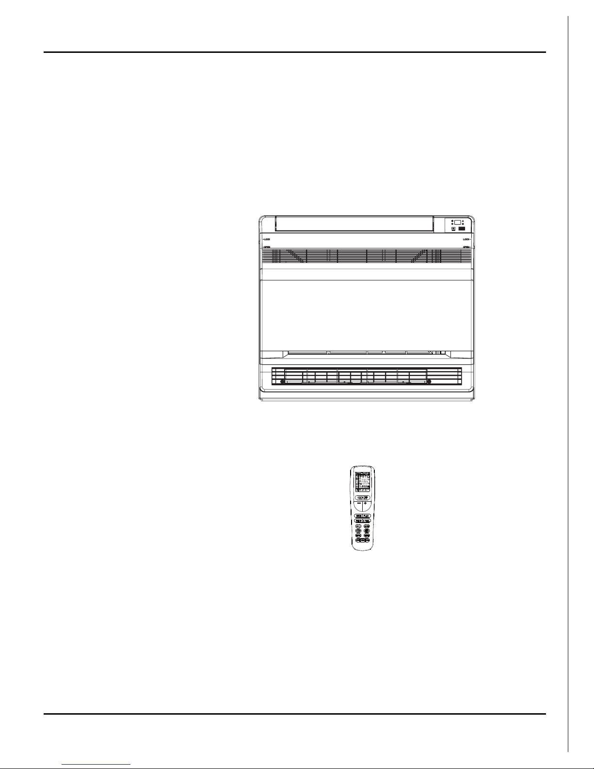
Summary and features
Indoor Unit:
Remote control
Summary and features
ACP-12CTIFM35GECI
ACP-18CTIFM50GECI
2
Safety Precautions
Installing, starting up, and servicing air conditioner can be
hazardous due to system pressure, electrical components,
and equipment location, etc.
Only trained, qualified installers and service personnel are
allowed to install, start-up, and service this equipment.
Untrained personnel can perform basic maintenance functions such as cleaning coils. All other operations should
be performed by trained service personnel.
When handling the equipment, observe precautions in the
manual and on tags, stickers, and labels attached to the
equipment. Follow all safety codes. Wear safety glasses
andwork gloves. Keep quenching cloth and fire extinguisher
nearby when brazing.
Read the instructions thoroughly and follow all warnings or
cautions in literature and attached to the unit. Consult local
building codes and current editions of national as well as
local electrical codes.
Recognize the following safety information:
Incorrect handling could result in
personal injury or death.
Incorrect handling may result in
minor injury,or damage to product
or property.
Warning
Caution
Caution
Warning
All electric work must be performed by a licensed technician
according to local regulations and the instructions given in
this manual.
Before installing, modifying, or servicing system, main
electrical disconnect switch must be in the OFF position.
There may be more than 1 disconnect switch. Lock out
and tag switch with a suitable warning label.
Never supply power to the unit unless all wiring and tubing are completed, reconnected and checked.
This system adopts highly dangerous electrical voltage.
Incorrect connection or inadequate grounding can cause
personal injury or death. Stick to the wiring diagram and
all the instructions when wiring.
Have the unit adequately grounded in accordance with
local electrical codes.
All installation or repair work shall be performed by your dealer or a specialized subcontractor as there is the risk of fire,
electric shock, explosion or injury.
Have all wiring connected tightly. Loose connection may
lead to overheating and a possible fire hazard.
Make sure the outdoor unit is installed on a stable, level
surface with no accumulation of snow, leaves, or trash
beside.
Make sure the ceiling/wall is strong enough to bear the
weight of the unit.
Make sure the noise of the outdoor unit does not disturb
neighbors.
Follow all the installation instructions to minimize the risk
of damage from earthquakes, typhoons or strong winds.
Avoid contact between refrigerant and fire as it generates
poisonous gas.
Apply specified refrigerant only. Never have it mixed with
any other refrigerant. Never have air remain in the
refrigerant line as it may lead to rupture and other hazards.
Make sure no refrigerant gas is leaking out when installation is completed.
Should there be refrigerant leakage, the density of refrigerant in the air shall in no way exceed its limited value,
or it may lead to explosion.
Keep your fingers and clothing away from any moving
parts.
Clear the site after installation. Make sure no foreign objects are left in the unit.
Always ensure effective grounding for the unit.
Never install the unit in a place where a combustible gas
might leak, or it may lead to fire or explosion.
Properly insulate any tubing running inside the room to
prevent the water from damaging the wall.
1.Safety Precautions
Make a proper provision against noise when the unit is
installed at a telecommunication center or hospital.
Provide an electric leak breaker when it is installed in a
watery place.
Never wash the unit with water.
Should any emergency occur, stop the unit and disconnect the power immediately.
Handle unit transportation with care. The unit should not
be carried by only one person if it is more than 20kg.
Never touch the heat exchanger fins with bare hands.
Never touch the compressor or refrigerant piping without
wearing glove.
Do not have the unit operate without air filter.
3
2.Specifications
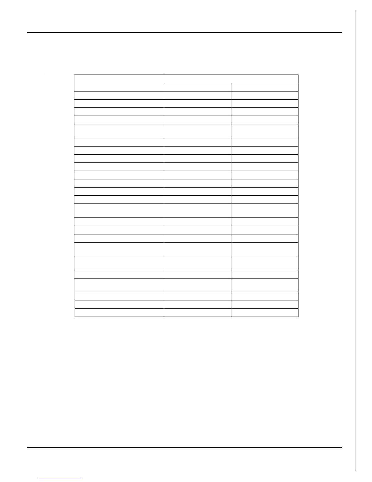
2.1 Unit Specifications
Specifications
The above data is subject to change without notice. Please refer to the nameplate of the unit.
ACP-12CTIFM35GECI ACP-18CTIFM50GECI
0600N010VC0
500N010VCedoC tcudorP
Capacity˄Cooling˅˄W
˅
00350053
Capacity˄Heating˅˄W
˅
00850083
Airflow˄m³/h
˅
056055
Fan Motor Speed (r/min)
(SH/H/HM/M/LM/L/S)
750/650/600/550/500/450/350840/800/720/650/580/530/41
0
0303)w( rotoM naF fo tuptuO
//)Fu( roticapaC rotoM naF
41.041.0)A(ALR rotoM naF
1-lagufirtneC1-lagufirtneCeceiP-epyT naF
Diameter-Length (mm) 370X80
370X80
munimulArotaropavE fin-copper tube Aluminum fin-copper tube
Pipe Diameter (mm) 7 7
2
.1-22.1-2)mm(paG niF-woR
Coil length (l) x height (H) x coil
width (L)
511X396X
24 511X396X24
BE42PMBE42PMledoM rotoM gniwS
5.15.1)W( rotoM gniwS fo tuptuO
A51.3 BCPA51.3 BCP)A( esuF
Sound Pressure Level dB (A)
(SH/H/M/L/SL)
45/42/38/37/35/32/31 50/48/44/43/41/40/39
Sound Powe
r Level dB (A)
(SH/H/M/L/SL)
55/52/48/47/45/42/41 60/58/54/53/51/50/49
Dimension (W/H/D) ( mm) 700X600X215 700X600X215
Dimension of Package (L/W/H)mm 788X695X283 788X695X283
Liquid connections Diameter
6(1/4ͳ) 6(1/4ͳ)
Gas connections Diameter
9.52(3/8ͳ) 12(1/2ͳ)
81/5181/51kg)( thgieW ssorG/ thgieW teN
Item
Console
4
Specifications
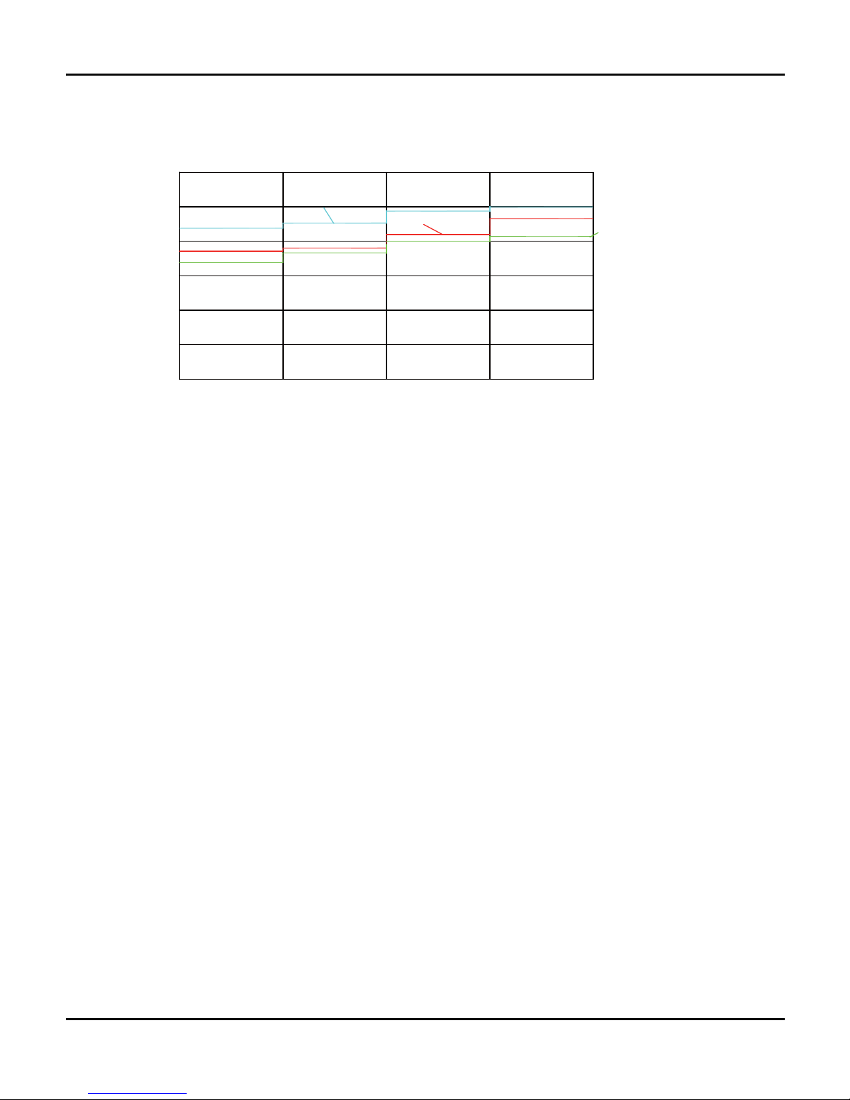
2.2 Noise Criteria Curve Tables for Both Models
0
10
Noise/dB(A)
20
30
40
50
60
Low
Middle High Super High
Indoor Fan Motor Rotating Speed
9K
12K
18K
5
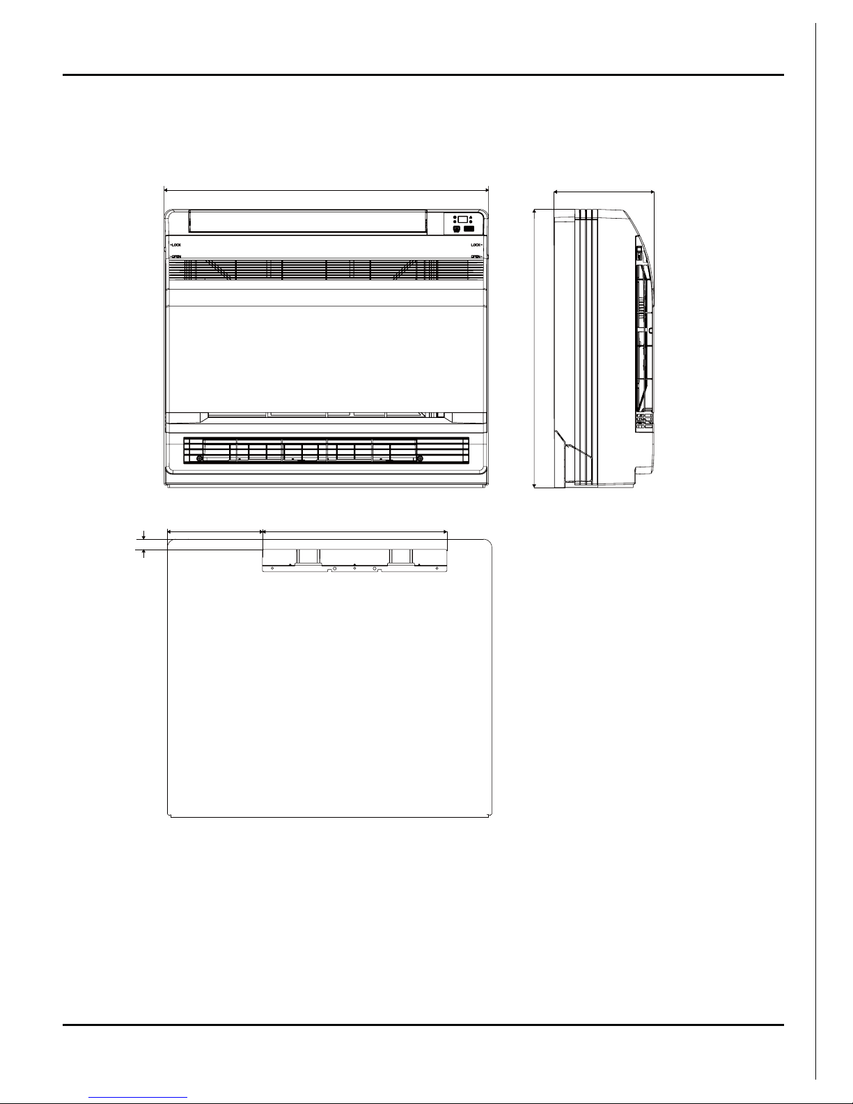
3. Construction Views
Constrction views
700
215
600
398
205
22
Unit:mm
6
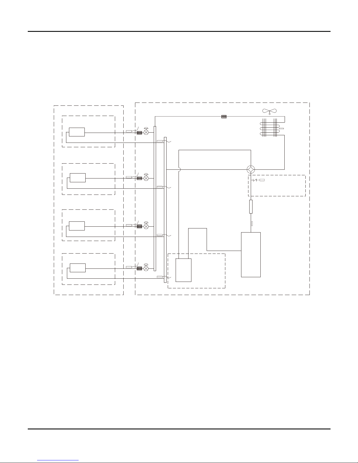
4. Refrigerant System Diagram
Refrigerant System Diagram
outdoor
indoor
D1
C
1
B
1
A
1
filter
A heat exchanger
gas -liquid separator
inverter compressor
discharge silencer
discharge temperature
sensor
SP
4-way valve
outdoor heat exchanger
fan
high pressure switch
B heat exchanger
C heat exchanger
D heat exchanger
filter
filter
filter
filter
Note: Not available for 14K/18K
model
C2
C3
D3
D2
B3
B2
A2
A3
A1:A-unit electronic expansion valve B1:B-unit electronic expansion valve
C1:C-unit electronic expansion valve D1:D-unit electronic expansion valve
A2:A-unit gas pipe temperature sensor B2:B-unit gas pipe temperature sensor
C2:C-unit gas pipe temperature sensor D2:D-unit gas pipe temperature sensor
A3:A-unit liquid pipe temperature sensor B3:B-unit liquid pipe temperature sensor
C3:C-unit liquid pipe temperature sensor D3:D-unit liquid pipe temperature sensor
Note: Not available for 14K/18K model
7
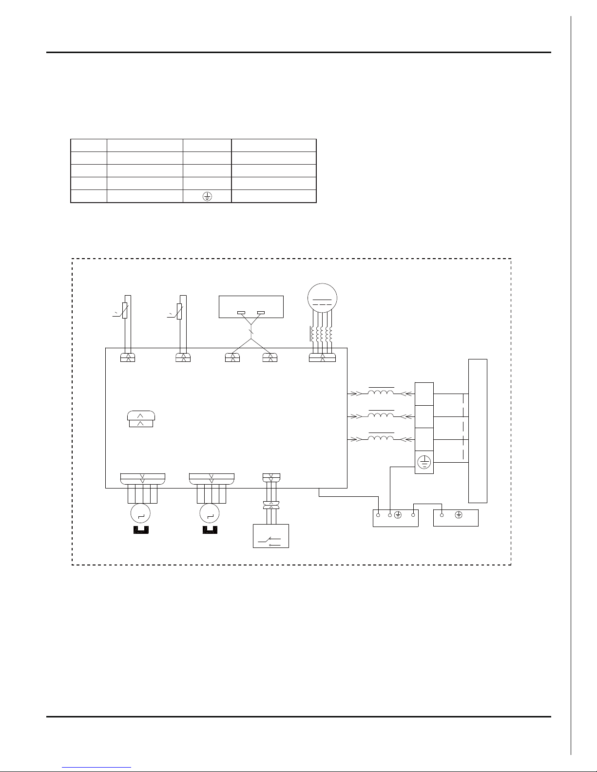
5. Schematic Diagram
5.1 Electrical Data
Meaning of marks
5.2 Electrical wiring
Symbol Color symbol Symbol Color symbol
WH WHITE BN BROWN
YE YEL LOW BU BLUE
RD RED BK BLACK
YEGN YELLOW GREEN PROTECTIVE EARTH
Schematic Diagram
YEGN
BK
BU
M3
SWING-DOWN
OUTDOOR UNIT
CAP
JUMP
AP1
ROOM
RT2
RT1
TUBE
SENSOR
SENSOR
ROOM
TUBE
N
DISPLAY
RECEIVER AND
DISPLAY BOARD
DISP2
AP2
DISP1
FAN
DC-MOTOR
MOTOR
TEMP.
TEMP.
STEPPING
SWING-UP
M2
AP3
S
CN8
SELECT
SWITCH
MOTOR
STEPPING
MOTOR
N(1)
2
XT
3
BN
COM-OUT
AC-L
1BU
2BK
3BN
4YEGN
L1
L1
PE
ELECTRICAL BOX
EVAPORATOR
PE
5YEGN
L2
E
YEGN
L1
0
0
M
These circuit diagrams are subject to change without notice, please refer to the one supplied with the unit.
8
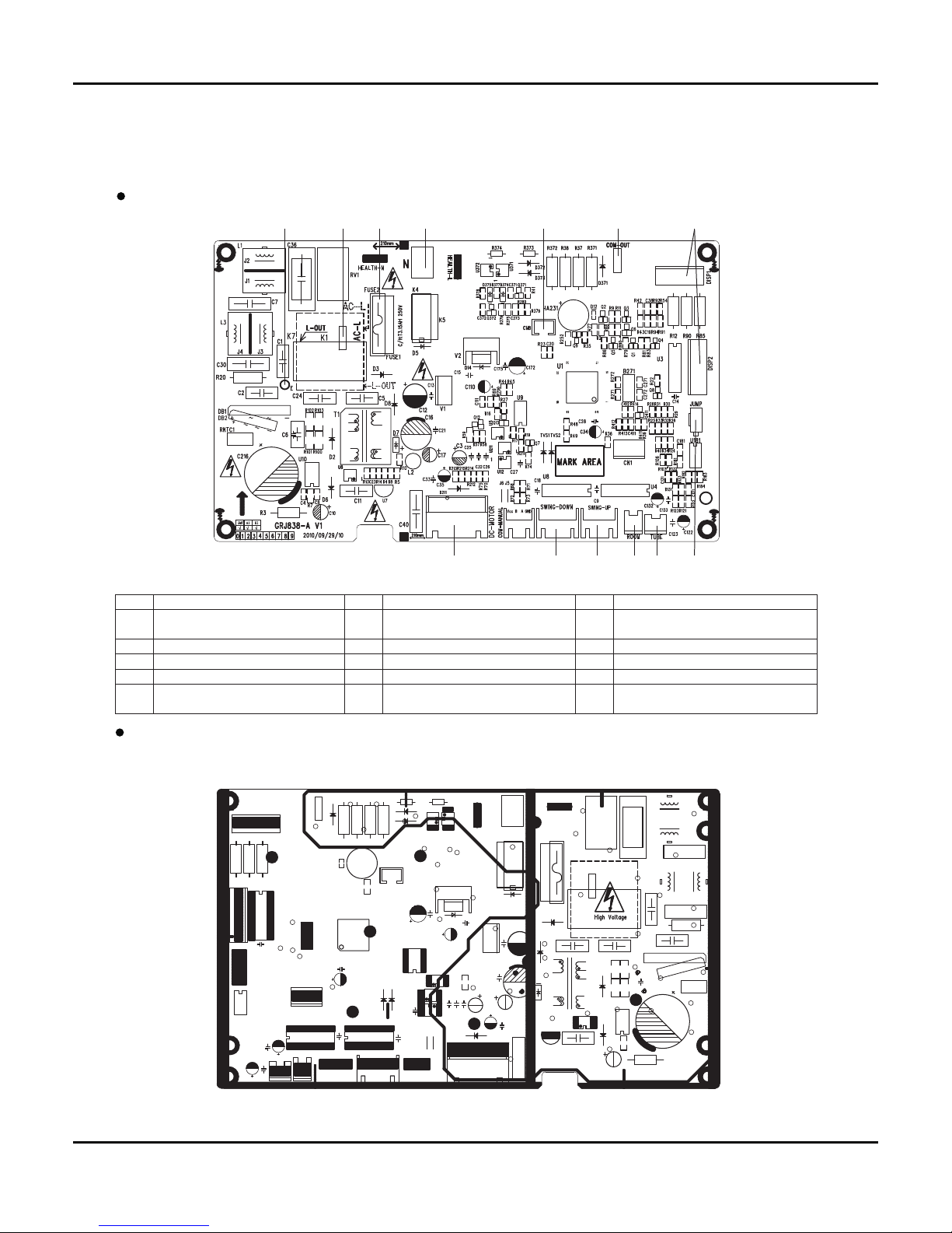
5.3 Printed Circuit Board
Schematic Diagram
BOTTOM VIEW
TOP VIEW
1234 5 6 7
89101113 12
No. Name No. Name No. Name
1
Terminal for earthing wire
6
Communication terminal for indoor
and outdoor units
11
Terminal for upper swing
2 Terminal for live wire 7 Terminal for display panel 12 Terminal for lower swing
3 Protective tube 8 Terminal for jumper cap 13 Terminal for DC fan
4 Terminal for neutral wire 9 Indoor tube temperature sensor 14
5
Terminal used for controlling the
lower swing switch
10
Indoor ambient temperature
sensor
15
9
6. Function and Control
Function and Control
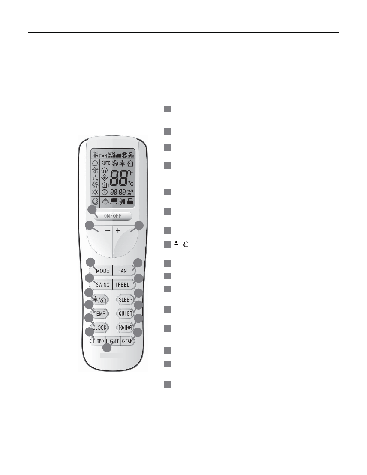
6.1 Remote Control Operations
72172))
Press it to start or stop operation.
ON/OFF
MODE
+
-
Press it to select operation mode
(AUTO/COOL/DRY/FAN/HEAT).
: Press it to increase temperature
setting.
:
Press it to decrease temperature
setting.
FA
N
Press it set swing angle.
QUIET
SWING
CLOCK
X-FAN
TEMP
TURBO
SLEEP
LIGHT
Press it to set fan speed.
Press it to s et
Press it to s et auto-off /auto-on timer.
Press it set clock.
1
7
Press it to set HEALTH or AIR function.
8
I FEEL
/
4
3
2
5
6
11
13
12
16
10
14
9
15
3
15
5
4
14
7
16
13
12
9
8
11
10
2
1
6
Press it to turn on/off the light.
QUIET function.
10
Function and Control
6
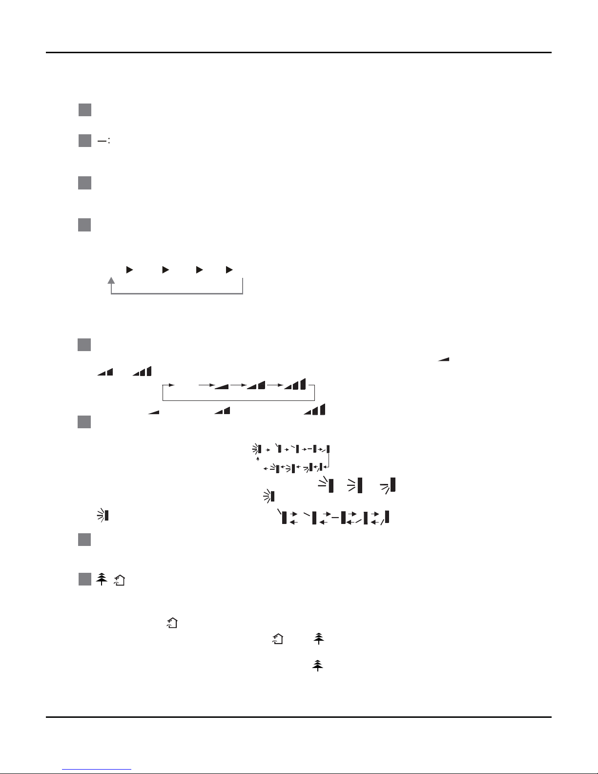
Press this button to set up &down swing angle, which circularly changes as below
:
OFF
This remote controller is universal . If any command , or is sent out,
the unit will carry out the command as
indicates the guide louver swings as:
Press this button to achieve the on and off of healthy and scavenging functions in
operation status.Press this button for the first time to start scavenging function;
LCD displays“ ”. Press the button for the
second time to start healthy and scavenging
functions simultaneously; LCD displays“ ” and “ ” .
Press this button for the third
time to
quit healthy and scavenging functions simultaneously. Press the button for the
fourth
time to start healthy function; LCD display “ ”
. Press this button again to repeat
the operation above.
/
8
Press this button to turn on I FEEL function. The unit automatically adjust temperature
according to the sensed temperature. Press this button again to cancel I FEEL function.
I FEEL:
SWING:
7
ON/OFF :
MODE :
+:
This button is used for setting Fan Speed in the sequence that goes from AUTO,
to
then back to Auto.
,
,
,
FAN :
1
4
3
2
5
Press this button to turn on the unit .Press this button again to turn off the unit.
Press this button to decrease set temperature. Holding it down above 2 seconds rapidly
decreases set temperature. In AUTO mode, set temperature is not adjustable.
Press this button to increase set temperature.Holding it down above 2 seconds rapidly
increases set temperature. In AUTO mode, set temperature is not adjustable.
Aut o
Low speed
Medium speed
High speed
Each time you press this button,a mode is selected in a sequence that goes from AUTO,
COOL,DRY, FAN,and HEAT
*
, as the following:
AUTO
COO L
DRY
FAN
*Note:Only for models with heating function.
After energization, AUTO mode is defaulted. In AUTO mode, the set temperature will not
be displayed on the LCD, and the unit will automatically select the suitable operation
mode in accordance with the room temperature to make indoor room comfortable.
HEAT
11
Function and Control
T-ON T-OFF:
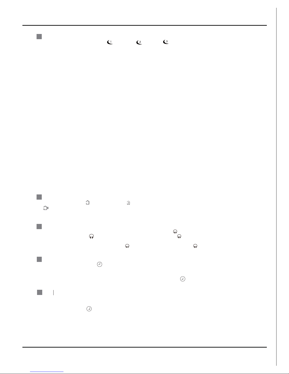
SLEEP:
9
Press this button, can select Sleep 1 ( ), Sleep 2 ( ),Sleep 3 ( ) and cancel the Sleep,
circulate between these, after electrified, Sleep Cancel is defaulted.
Sleep 1 is Sleep mode 1, in Cool, Dehumidify modes: sleep status after run for one hour, the main
unit setting temperature will increase 1
present time.Holding down either button above 2 seconds increases or decreases the
CLOCK :
time by 1 minute every 0.5 second and then by 10 minutes every 0.5 second. During
blinking after setting, press CLOCK button again to confirm the setting,and then
10
TEMP:
Press T-ON button to initiate the auto-ON timer. To cancel the auto-timer program, simply
press this button again.
After press of this button, disappears and "ON "blinks .0
0:00 is displayed for ON time
setting. Within 5 seconds, press + or - button to adjust the time value. Every press of either
button changes the time setting by 1 minute. Holding down either button rapidly changes the
time setting by 1 minuteand then 10 minutes. Within 5 Seconds after setting, pressTIMER
ON button to confirm.
Pressing TEMP button, (set temperature), (indoor ambient temperature) and
(outdoor ambient temperatur) and blank is displayed circularly .The unit defaults not to
display the icon. During operation of TEMP button, the set temperature is always displayed.
12
will
be constantly displayed.
QUIET:
11
13
Note: Outdoor ambient temperature is only displayed for some models.
Press T-OFF button to initiate the auto-off timer. To cancel the auto-timer program, simply
press the button again.TIMER OFF setting is the same as TIMER ON.
Press this button, the Quiet status is under the Auto Quiet mode (display " "signal )
and Quiet mode (display " " singal) and Quiet OFF (there is no signal of " " displayed),
after powered on, the Quiet OFF is defaulted. Note: the Quiet function cannot be set up in Fan
and Dry mode;Under the Quiet mode (Display " " Under the Quiet mode (Display " "
signal), the fan speed is not available.
Press CLOCK button, blinking . Within 5 seconds,pressing +or - button adjusts the
Sleep 3- the sleep curve setting under Sleep mode by DIY:
(1) Under Sleep 3 mode, press "Turbo" button for a long time, remote control enters into user individuation sleep
setting status, at this time, the time of remote control will display "1hour ", the setting temperature "88" will
(2) Adjust "+" and "-" button, could change the corresponding setting temperature, after adjusted, press
"Trubo "button for confirmation;
(3) At this time, 1hour will be automatically increased at the timer postion on the remote control, (that are
(4) Repeat the above step (2)
(3) operation, until 8hours temperature setting finished, sleep
curve setting finished, at this time, the remote control will resume the original timer display;
display the corresponding temperature of last set ting sleep cur ve and blink (The first entering will display
according to the initial curve setting value of original factory);
"2hours " or "3hours " or "8hours "), the place of setting temperature "88" will display the
corresponding temperature of last setting sleep curve and blink;
temperature display will resume to original setting temperature.
●
●
Sleep3- the sleep curve setting under Sleep mode by DIY could be inquired:
The user could accord to sleep curve setting method to inquire the presetting sleep curve, enter into user
individuation sleep setting status, but do not change the temperature, press "Turbo" button directly for confirmation.
Note: In the above presetting or enquiry procedure, if continuously within10s, th ere is no butto n presse d, the
sleep curve setting within10s, there is no button pressed, the sleep curve setting status will be automatically
quit and resume to display the original displaying. In the presetting or enquiry procedure, press "ON/OFF"
button, "Mode" button, "Timer"button or "Sleep" button, the sleep curve setting or enquiry status will quit similarly.
●
●
ć,setting temperature increased 2 ć, the unit will run at this
setting temperature; In Heat mode: sleep status after run for one hour, the setting temperature will
decrease 1
ć, 2 hours, setting temperature will decrease 2
ć, then the unit will run at this setting
temperature.
●
Sleep 2 is sleep mode 2, that is air conditioner will run according to the presetting a group of sleep temperature curve.
 Loading...