

Vivax cool ACP-12CC35GECI, ACP-18CF50GECI, ACP-36CC100GECI, ACP-24CF70GECI, ACP-36CF100GECI Service Manual
...
ACP-12CC35GECI
ACP-18CC50GECI
ACP-24CC70GECI
ACP-36CC100GECI
ACP-18CF50GECI
ACP-24CF70GECI
ACP-36CF100GECI
Service
manual
ENG
RoHS
NNO-1/09

GREE COMMERCIAL AIR CONDITION A/A DC INVERTER U-MATCH AIR CONDITIONERS
1
PRODUCT
A/A DC INVERTER U-MATCH AIR CONDITIONERS PRODUCT
2
PRODUCT
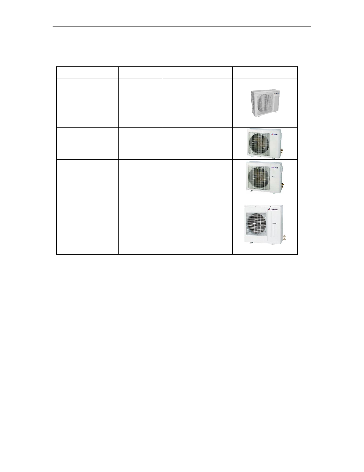
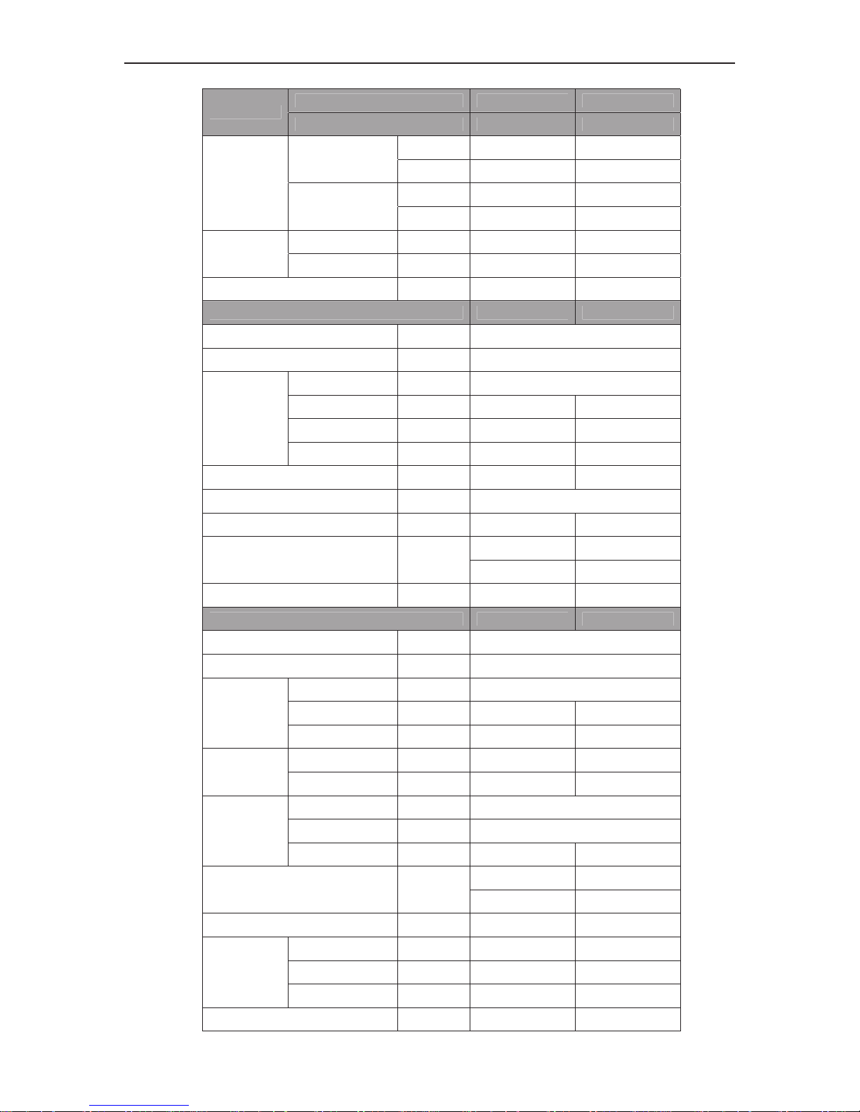
1 MODELS LIST
1.1 Outdoor Unit
Model Name Ref.
Power supply
(V, Ph, Hz)
Appearance
ACP-12CC35GECI R410A 220-240 V 1 Ph ~ 50 Hz
R410A 220-240 V 1 Ph ~ 50 Hz
R410A
220-240 V 1 Ph~ 50 Hz
R410A 220-240 V 1 Ph~ 50 Hz
ACP-18CC50GECI
ACP-18CF50GECI
ACP-24CC70GECI
ACP-24CF70GECI
ACP-36CC100GECI
ACP-36CF100GECI
Note:1 Ton =12000Btu/h = 3.517kW
A/A DC INVERTER U-MATCH AIR CONDITIONERS PRODUCT
3
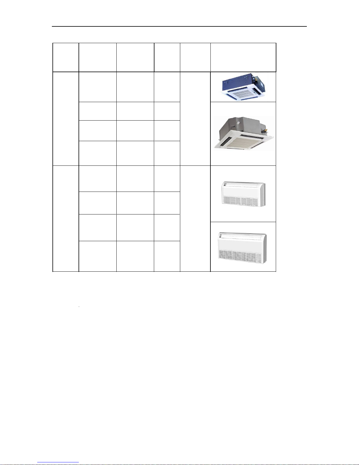
1.2 Indoor Unit
Type Model Name
Nominal
Capacity
Cooling/Heati
ng
(Btu/h)
Ref.
Power
supply
(V, Ph, Hz)
Appearance
ACP-12CC35GECI 12000/12600 R410A
18000/21000 R410A
24000/29500 R410A
35140/38210 R410A
Cassette
Type
220-240 V
1Ph~
50Hz
12000/13000 R410A
18000/21000 R410A
24000/27000 R410A
36167/40944 R410A
220-240 V
1Ph~
50Hz
Ceiling
Type
ACP-18CC50GECI
ACP-18CF50GECI
ACP-24CC70GECI
ACP-24CF70GECI
ACP-18CC50GECI
ACP-18CF50GECI
ACP-24CC70GECI
ACP-24CF70GECI
ACP-12CC35GECI
ACP-36CC100GECI
ACP-36CF100GECI
ACP-36CC100GECI
ACP-36CF100GECI
Note:1 Ton =12000Btu/h = 3.517kW
A/A DC INVERTER U-MATCH AIR CONDITIONERS PRODUCT
4
NOTES:
The universal outdoor units means that the customer can choose any of three kind of indoor unit to match the
outdoor unit without any change with it.
2 NOMENCLATURE
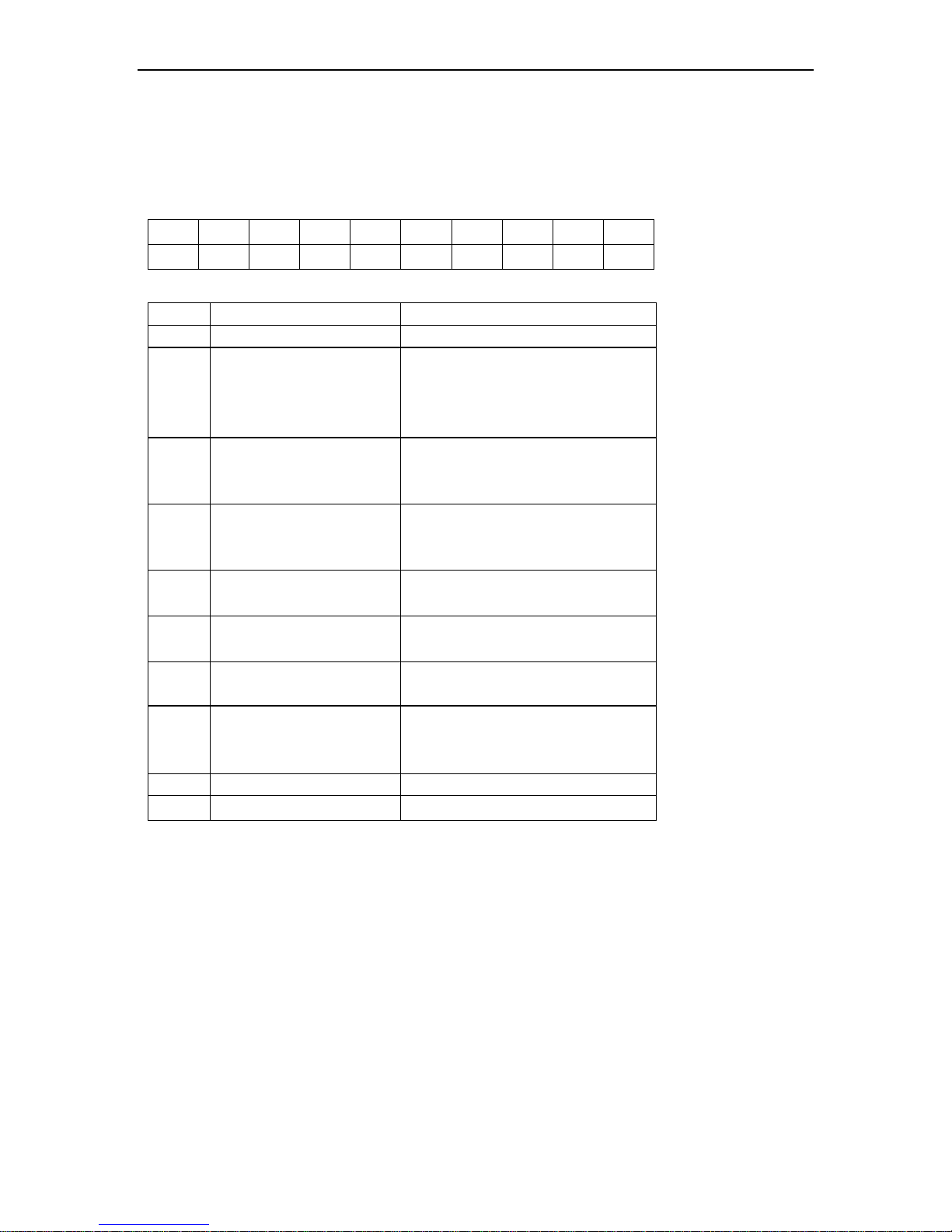
G U H D 09 N K 3 A O
1 2 3 4 5 6 7 8 9 10
NO. Description Options
1 Gree Electric Appliances Inc Capital Letter :G
2 Unit Type
U=Match Outdoor Unit
F=Duct Type
K=Cassette Type
T= Floor-ceiling Type
3 Product Type
C=Cool Only
H=Heat Pump without Aux Electric
Heaters
4
Compressor Power Supply
Type Code
N=Constant Frequency
D=DC Inverter
A=AC Inverter
5 Nominal Cooling Capacity
Nominal Cooling Capacity
=Number×1000Btu/h
6 Climate Type
N=Climate T1 Condition
T= Climate T3 Condition
7 Power Supply Code
K=1Ph 220~240V 50HZ
M=3Ph 380~415V 50HZ
8 Refrigerant
1 =R22
2=R407C
3=R410A
9 Design Code Design Code: A, B, C, D……
10 Unit Code I=indoor unite O=Outdoor unit
A/A DC INVERTER U-MATCH AIR CONDITIONERS PRODUCT
5
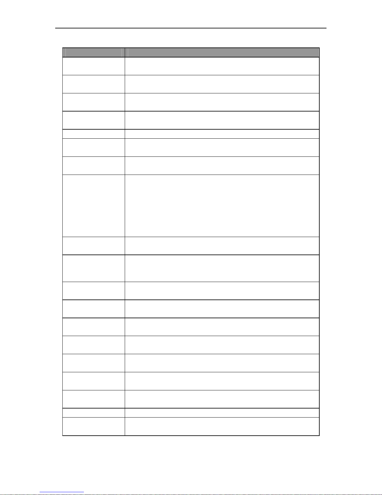
3 FUNCTION
Function Description
Memory function
when unit restarts after power off, it will run on former status, the mode and
parameter are kept the same
Remote control function
wireless controller and remote controller can be selected, and the maximum
control distance of remote controller is 10m.
Timing function
it can timing ON/ OFF separately, meanwhile, it can also timing on circularly
Self-diagnosis with
alarm function
Once the unit has malfunction, the malfunction code will be indicated and alarm
rings immediately
Sleep function it can self control for saving energy in energy saving mode.
Automatic function
the fan of indoor unit can adjust fan speed automatically based on actual
demand when cooling or heating under automatic mode
Cool air proof function
the fan starts only when the temperature of indoor unit heat exchanger is higher
than indoor temperature under heating mode
Weekly Time
Centralized Control and Weekly Timer Functions: The centralized controller and
the weekly timer are integrated in the same wire controller. The system has both
the centralized control and the week timing functions. Up to 16 sets of units can
be controlled simultaneously by the centralized controller (weekly timer). The
weekly timer has the function of invalidating the lower unit. The weekly timing
function is able to realized four timing ON/OFF periods for any unit every day, so
as to achieve fully automatic operation. No timing control can be set for holidays.
High/low pressure
protection
when suction pressure is too low or discharge pressure is too high, compressor
will stop and unit display malfunction code
Overload protection
compressor has its own overheat protection.Once the temperature of
compressor is higher than allowable level, compressor will stop and only when
temperature recovery, compressor restart
Over current protection
once the current of compressor is higher than normal level, compressor will stop
and unit display malfunction code
Discharge high
temperature protection
once the discharge temperature of compressor is higher than allowable value,
compressor will stop and unit display malfunction code
Reverse (open) phase
protection
once the phase sequence of power supply is incongruent or the phase is absent,
unit can’t work.
Anti-high temperature
protection
once the heat exchanger temperature of indoor unit is too high, the outdoor fan
motor will stop.
Timing ON/OFF display
display and timing turn ON/OFF time( only with wired controller have this
function)
Fan speed display
display the speed (high,medium,low) of fan(only with wired controller have this
function)
Function model display
cooling mode,dry mode,heating mode,fan mode(only with wired controller have
this function)
Testing display display testing mode(only with wired controller have this function)
Temperature display
display room temperature and set temperature(only with wired controller and
remoter board have this function)
A/A DC INVERTER U-MATCH AIR CONDITIONERS PRODUCT
11
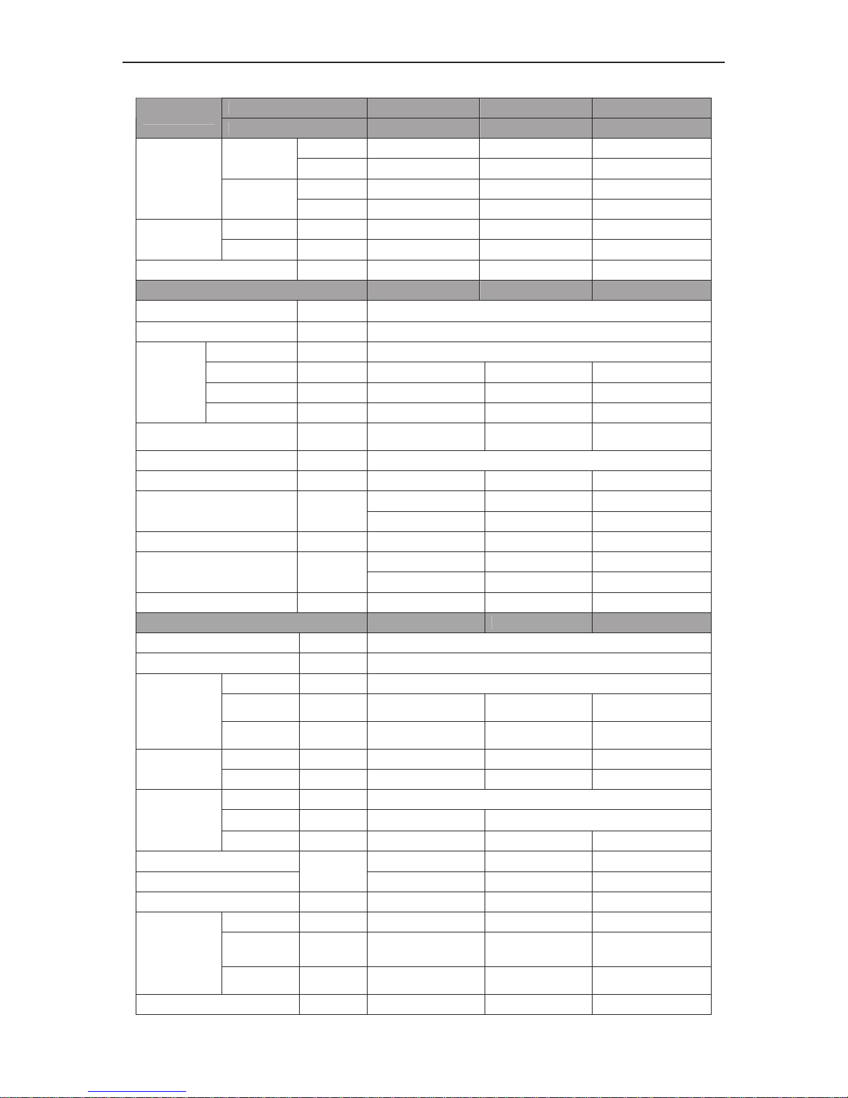
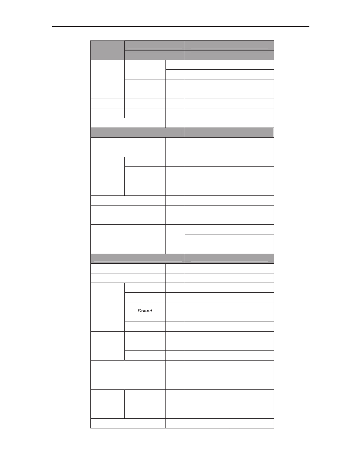
4.1.2 Cassette Type
Indoor unit ACP-12CC35GECI
ACP-18CC50GECI
ACP-24CC70GECI
Model
Outdoor unit ACP-12CC35GECI
ACP-18CC50GECI
ACP-24CC70GECI
kW
3.4
5.3 7
Cooling
Btu/h
11600
18000 24000
kW
3.7
6.15 8.65
Nominal
Capacity
Heating
Btu/h
12600
21000 29500
Cooling kW
1.03
1.65 2.19
Power Input
Heating kW
1.025
1.7 2.4
EER/COP
W/W
3.2/3.61 3.21/3.61 3.20/3.61
Indoor Unit
ACP-12CC35GECI
ACP-18CC50GECI ACP-24CC70GECI
Power Supply
-
220-240V-50Hz-1Ph
Heat Exchange - Cross Fin Coil
Type - Centrifugal fan
Drive - direct direct direct
Motor Output kW 0.011x1 0.035×1 0.040×1
Fan
Air Flow
m3/h
550 1180 1400
Sound Pressure
Level(H/M/L)
dB(A) 47/45/43 47/45/43 51/49/48
Air Filter - Standard washable synthetic
Drain Piping mm Φ32×3 Φ32×3 Φ32×3
600×230×600 840×240×840 840×240×840
Indoor Unit Dimensions
(Outline/Package) (W×H×D)
mm
848×310×678 960×310×960 960×310×960
Weight(Net/Gross) kg 20/27 27/36 27/36
650 x50x650 950×60×950 950×60×950
Panel Dimensions
(Outline/Package) (W×H×D)
mm
670 x102x730 1025×115×1040 1025×115×1040
Panel Weight(Net/Gross) kg 2.5/3.5 6.5/10 6.5/10
Outdoor Unit ACP-12CC35GECI
ACP-18CC50GECI
ACP-24CC70GECI
Power Supply - 220-240V-50Hz-1Ph
Heat Exchange - Cross Fin Coil
Type - Axial fan
Motor
Output
kW 0.75x1 0.06×1 0.09×1
Fan
Fan Motor
Speed
rpm 1070 690±15 780±20
Type - ROTARY ROTARY ROTARY
Compressor
Power Input W 850 1630 2200
Type - R410A
Control
-
Caplllary Tube Electronic Expansion Valve
Refrigerant
Charge kg 1.35 1.4 2.4
Dimensions (W×H×D) 776×320×540 955×700×396 980×790×427
(Outline/Package)
mm
848×360 ×580 1026× 735×455 1080×840×485
Weight(Net/Gross) kg 30/34 48/53 65/70
Liquid Inch Φ1/4" Φ1/4" Φ3/8"
Gas Inch Φ3/8" Φ1/2" Φ5/8"
Piping
Connections
Max.
Length
m 20 20 30
Max. Height Difference m 15 15 15
A/A DC INVERTER U-MATCH AIR CONDITIONERS PRODUCT
12
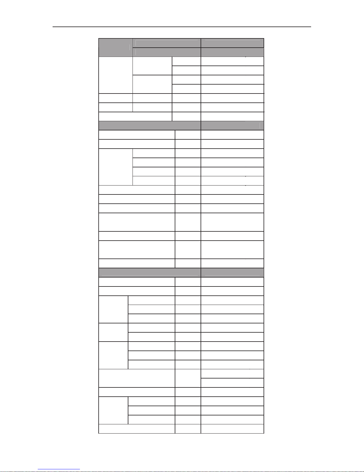
Continued
1
Indoor unit
ACP-36CC100GECI
Model
Outdoor unit ACP-36CC100GECI
kW 10.3
Cooling
Btu/h 35140
kW 11.2
Nominal
Capacity
Heating
Btu/h
38210
Power Cooling kW 3.2
EER/COP
W/W
3.22/3.73
Indoor Unit
ACP-36CC100GECI
Power Supply
-
220-240V-50Hz-1Ph
Heat Exchange
-
Cross Fin Coil
Type
-
Centrifugal fan
Drive
-
direct
Motor Output kW
0.06
Fan
Air Flow
m3/h
1660
Sound Pressure Level(H/M/L) dB(A) 53/51/48
Air Filter
-
Standard washable synthetic
Drain Piping mm
Φ32×3
Indoor Unit Dimensions
840×320×840
(Outline/Package) (W×H×D)
mm
960×394×960
Weight(Net/Gross) kg 32/43
Panel Dimensions 950×60×950/
(Outline/Package) (W×H×D)
mm
1025×115×1040
Panel Weight(Net/Gross) kg 6.5/10
Outdoor Unit ACP-36CC100GECI
Power Supply
-
220-240V-50Hz-1Ph
Heat Exchange
-
Cross Fin Coil
Type
-
Axial fan
Motor Output kW
0.75×1
Fan
02±028
mpr deepS rotoM naF
Type
-
ROTARY
Compress
or
Power Input W 3010±7.5%
Type
-
R410A
Control
-
Electronic Expansion Valve
Refrigera
nt
Charge kg 3.5
1107×1100×440
Dimensions (W×H×D)
(Outline/Package)
mm
1155×1220×490
Weight(Net/Gross) kg 86/97
Liquid Inch
Φ3/8"
Gas Inch
Φ5/8"
Piping
Connectio
ns
Max. Length m 30
Max. Height Difference m
15
A/A DC INVERTER U-MATCH AIR CONDITIONERS PRODUCT
15
Continued
Indoor unit ACP-18CF50GECI ACP-24CF70GECI
Model
Outdoor unit ACP-18CF50GECI ACP-24CF70GECI
kW 5.3 7
Cooling
Btu/h 18000 24000
kW 6.15 8
Nominal
Capacity
Heating
Btu/h
21000 27000
Cooling kW 1.65 2.19
Power
Input
Heating kW 1.7 2.22
EER/COP
W/W
3.21/3.61 3.20/3.60
Indoor Unit
ACP-18CF50GECI ACP-24CF70GECI
Power Supply
-
220-240V-50Hz-1Ph
Heat Exchange
-
Cross Fin Coil
Type
-
Centrifugal fan
Drive
-
Direct Direct
Motor Output kW 0.02×1 0.05×1
Fan
Air Flow
m3/h
900 1200
Sound Pressure Level(H/M/L) dB(A) 45/42/39 52/49/46
Air Filter
-
Standard washable synthetic
Drain Piping mm Φ17×1.75 Φ17×1.75
1220×225×700 1220×225×700
Dimensions (W×H×D)
(Outline/Package)
mm
1345×310×825 1345×310×825
Weight(Net/Gross) kg 42/51 43/52
Outdoor Unit ACP-18CF50GECI ACP-24CF70GECI
Power Supply
-
220-240V-50Hz-1Ph
Heat Exchange
-
Cross Fin Coil
Type
-
Axial fan
Motor Output kW 0.06×1 0.09×1
Fan
Fan Motor Speed rpm 690±15 780±20
Type
-
ROTARY ROTARY
Compressor
Power Input W 1630 2200
Type
-
R410A
Control
-
Electronic Expansion Valve
Refrigerant
Charge kg 1.4 2.4
955×700×396 980×790×427
Dimensions (W×H×D)
(Outline/Package)
mm
1026× 735×455 1080×840×485
Weight(Net/Gross) kg 48/53 65/70
Liquid Inch Φ1/4" Φ3/8"
Gas Inch Φ1/2" Φ5/8"
Piping
Connections
Max. Length m 20 30
Max. Height Difference m 15 15
A/A DC INVERTER U-MATCH AIR CONDITIONERS PRODUCT
16
Continued:2
Indoor unit
ACP-36CF100GECI
Model
Outdoor unit
ACP-36CF100GECI
kW 10.6
Cooling
Btu/h 36160
kW 12
Nominal
Capacity
Heating
Btu/h
40940
Power Cooling kW 3.26
Input Heating kW 3.16
EER/COP
W/W
3.25/3.8
Indoor Unit
ACP-36CF100GECI
Power Supply - 220-240V-50Hz-1Ph
Heat Exchange - Cross Fin Coil
Type - Centrifugal fan
Drive -
Direct
Motor Output kW 0.15
Fan
Air Flow
m3/h
2000
Sound Pressure Level(H/M/L) dB(A) 54/51/48
Air Filter -
Standard washable synthetic
Drain Piping mm Φ17×2.5
1420×245×700
Dimensions (W×H×D)
(Outline/Package)
mm
1545×330×825
Weight(Net/Gross) kg 53/61
Outdoor Unit ACP-36CF100GECI
Power Supply - 220-240V-50Hz-1Ph
Heat Exchange - Cross Fin Coil
Type - Axial fan
Motor Output kW 0.75×1
Fan
Fan Motor
02±028 mpr
Type - YRATOR
Compressor
Power Input W 3010±7.5%
Type - A014R
Control - Electronic Expansion Valve
Refrigerant
Charge kg 3.5
1107×1100×440
Dimensions (W×H×D)
(Outline/Package)
mm
1155×1220×490
Weight(Net/Gross) kg
86/97
Liquid Inch Φ3/8"
Gas Inch Φ5/8"
Piping
Connections
Max. Length m 30
Max. Height Difference m 15
A/A DC INVERTER U-MATCH AIR CONDITIONERS PRODUCT
19
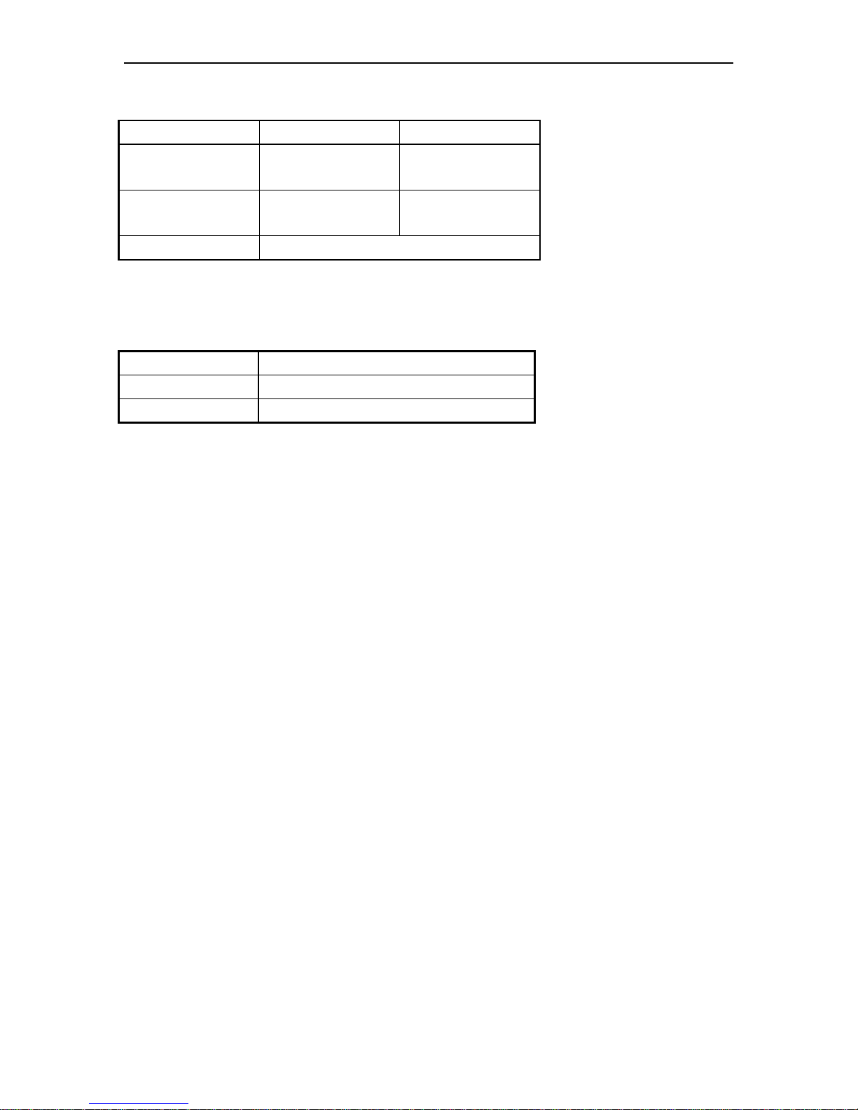
Note:
① Nominal capacities are based on the follow conditions.
Mode Indoor Outdoor
Cooling
DB:27 (80.6 )
WB:19 (66.2 )
DB:35 (95 )
WB:24 (75.2 )
Heating
DB:20 (68 )
WB:-- ( -- )
DB:7(44.6)
WB:6(42.8)
Piping Length 5m
② The air volume is measured at the relevant standard external static pressure.
③ Noise is tested in the Semianechoic room, so it should be slightly higher in the actual operation due to
environmental change.
4.2 Operation Range
Mode Range of Outdoor Temperature ( )
Cooling 18-48
Heating -7-24
A/A DC INVERTER U-MATCH AIR CONDITIONERS PRODUCT
20
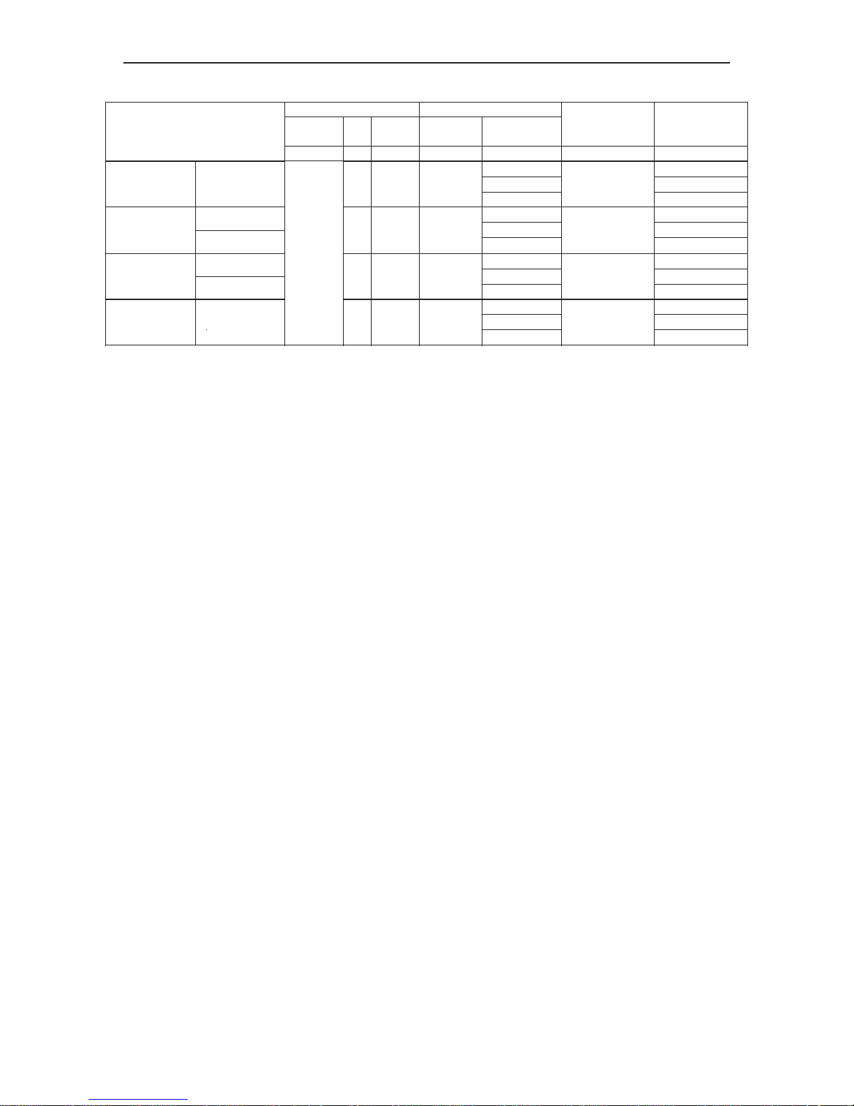
4.3 Electrical Data
Compressor Fan Motor
Power
Supply
Qty. RLA
Condenser
Fan Motors
Supply Blower
Motor
Max. Fuse
Breaker Size
(Indoor/Outdoor)
Min.
Disconnect Size
(Indoor/Outdoor)
Model
V,Ph,Hz — Each FLA Each FLA Each Amperes Amperes
5.2/0.1 A14.0
5.2/0.1 A01.0
ACP-12CC35GECI 1 4.8 0.35
0.2A
6/16
1.0/2.5
0.4/0.1 A17.0
0.4/0.1 A12.0
ACP-18CC50GECI
ACP-18CF50GECI
1
8.38/7.07
0.58
0.35A
6/20
1.0/4.0
0.4/5.1 A25.1
0.4/5.1 A15.0
ACP-24CC70GECI
ACP-24CF70GECI
1 9.7
0.85
0.40A
10/20
1.5/4.0
0.6/5.1 A50.5
0.6/5.1 A25.1
ACP-36CF100GECI
1 13.5
1.1
0.61A
10/32
1.5/6.0
220-240
1,
50
Notes:
RLA:Rated load amperes
LRA:Locked rotor amperes
FLA:Full load current
ACP-18CC50GECI
ACP-18CF50GECI
ACP-24CC70GECI
ACP-24CF70GECI
ACP-36CF100GECI
A/A DC INVERTER U-MATCH AIR CONDITIONERS PRODUCT
21
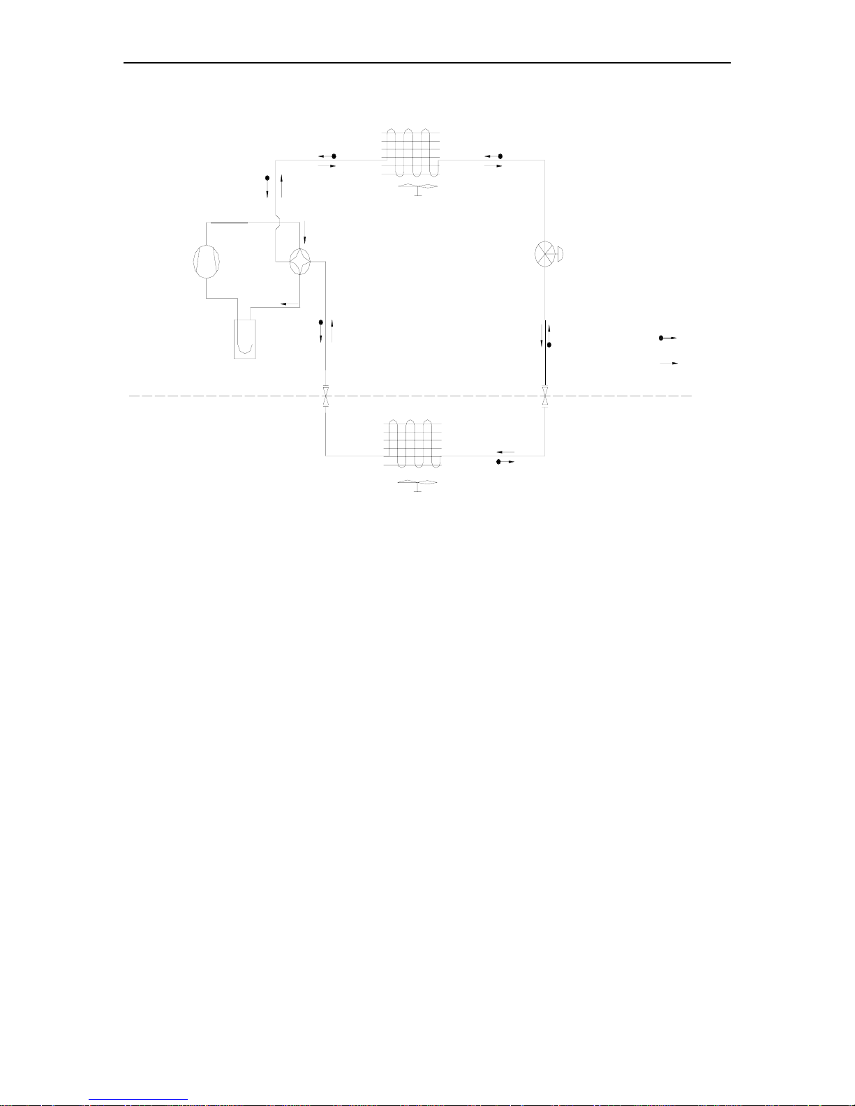
5 PIPING DIAGRAM
Indoor
Outdoor
Cool i ng
Heati ng
Throt tl e
Compr ess or
Vapour Liquid Separator
4-way Valve
Outdoor Heat Exchange
Indoor Heat Exchange
Throttling Method:
ACP-12CC35GECI:Capillary Tube
ACP-24CC70GECI, ACP-36CC100GECI,
ACP-18CF50GECI, ACP-24CF70GECI
ACP-36CF100GECI
:Electronic expansion valve

GREE COMMERCIAL AIR CONDITION A/A DC INVERTER U-MATCH AIR CONDITIONERS
22
CONTROL
A/A DC INVERTER U-MATCH AIR CONDITIONERS CONTROL
23
CONTROL
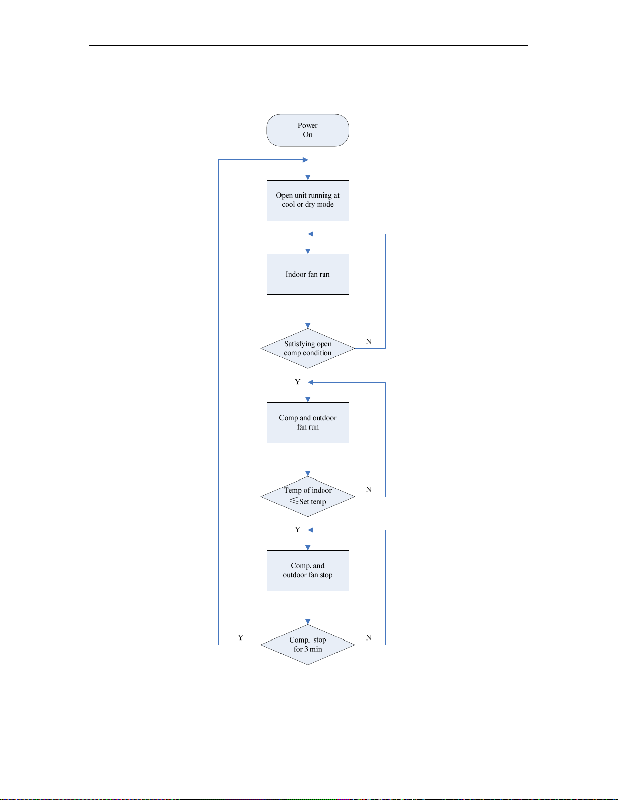
1 OPERATION FLOWCHART
1.1Cooling/Dry Operation
A/A DC INVERTER U-MATCH AIR CONDITIONERS CONTROL
24
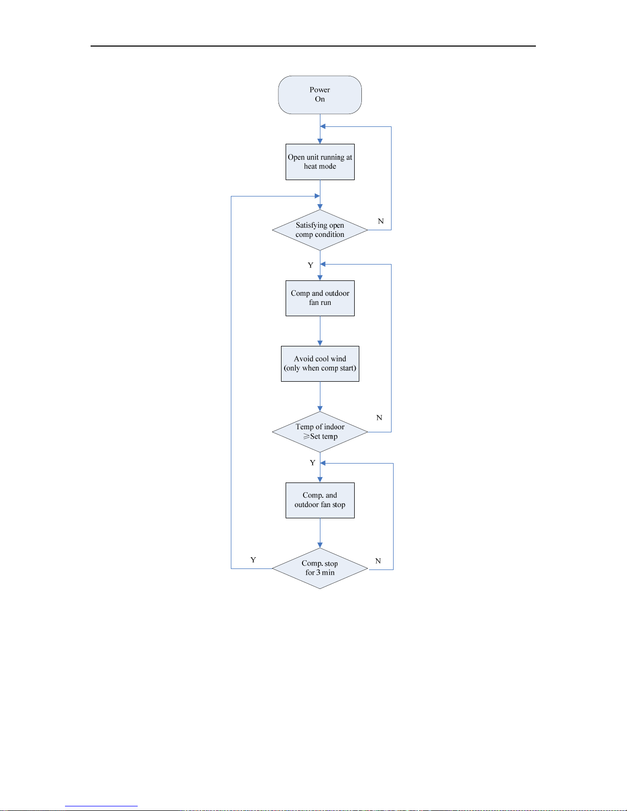
1.2 Heating Operation
A/A DC INVERTER U-MATCH AIR CONDITIONERS CONTROL
25
2 MAIN LOGIC
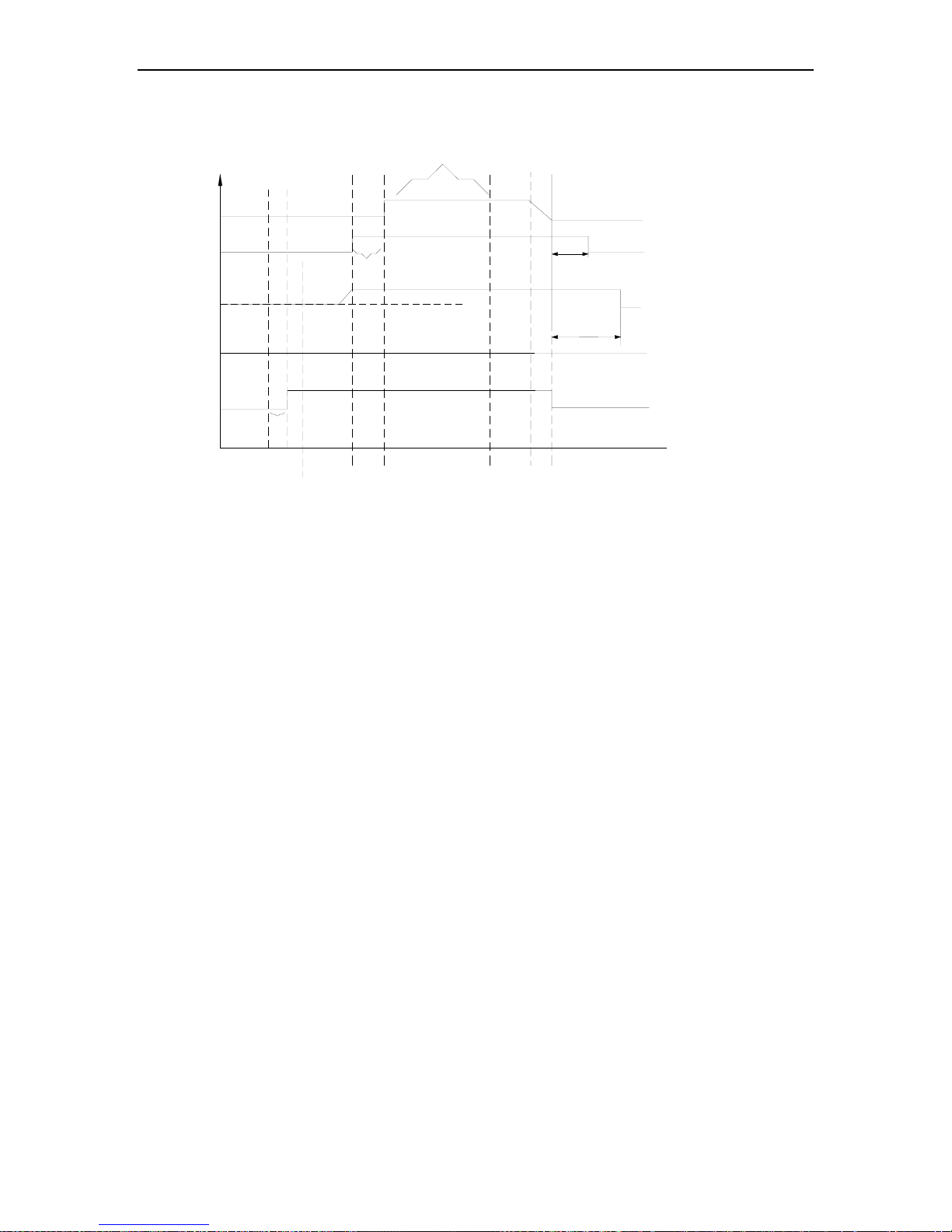
2.1 Cooling
Acc.to control
logic
Cooling mode
3min
Firstly switch off to step 0 and
then switch off step 60
150s atfer the compressor is stoped
180steps
Send out switch-off command
Acc.to control
logic
capacity demand>0
send out cooling
command
Indoor fan
(cooling)
4-way valve
3s
Xsteps
30s
ON
ON
ON
OFF
OFF
OFF
Outdoor fan
EXV
compressor
OFF
60s
60s
After the cooling command is sent out, the indoor fan will run at high speed for 5 seconds before it is put into
operation according to the setting. Then, it is started to calculate the system load demand value. If the load is 0, the
other loads except the indoor fan will not be put into operation (The water pump will run according to the pump
control logic behind). If the load is >0, the EXV will be firstly opened to step X; then the indoor fan is started. After 30
seconds, the compressor is started at initial frequency 40Hz and will be maintained for 3 minutes. After that, the
compressor, EXV and outdoor fan will adjust according to logic.
A/A DC INVERTER U-MATCH AIR CONDITIONERS CONTROL
26
2.2 Dry Mode
Max.capacity out put:A×90%
3min
Firstly switch off to step 0
and then switch off step 60
150s atfer the compressor is stoped
180steps
Send out switch-off command
Acc.to controll
logic
capacity
demand
>0
send out dry
command
Indoor fan
(cooling)
4-way valve
3s
Xsteps
30s
ON
ON
ON
OFF
OFF
OFF
Outdoor fan
EXV
Compressor
OFF
Dry Mode
Acc.to controll
logic
60s
150s
The dry mode is basically same as cooling mode. The difference is that:
The indoor fan is fixed at low speed.
Max. capacity output: A×90%

A/A DC INVERTER U-MATCH AIR CONDITIONERS CONTROL
27
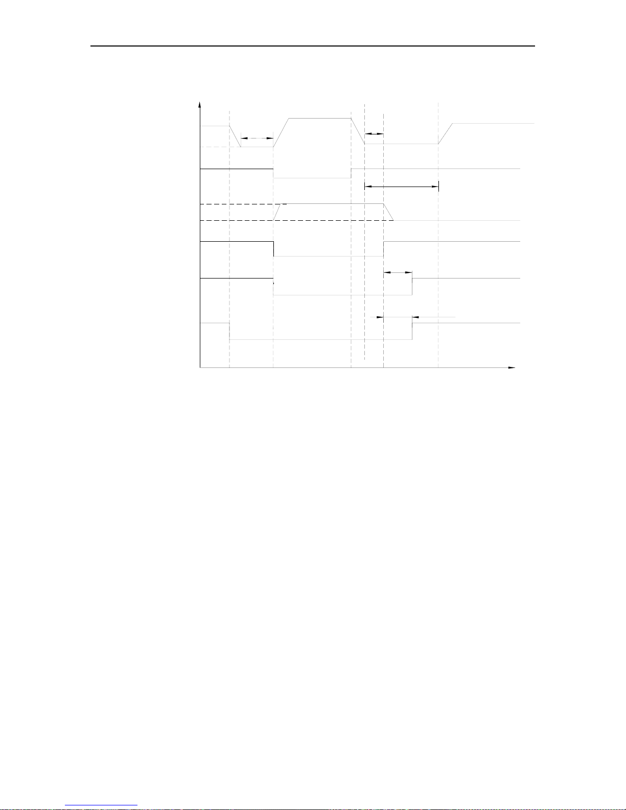
2.3 Heating Mode
150s atfer the compressor is stoped
Firstly switch off to step 0 and
then switch off step 60
Send out switch-off command
Acc.to controll
logic
Acc.to controll
logic
Xsteps
ON
ON
ON
OFF
Heating mode
3min
3s
OFF
OFF
OFF
compressor
EXV
outdoor fan
4-way valve
Indoor fan
(cooling)
send out heating
command
capacity
demand
>0
10s
Run as per cold air
prevention mode
30s
60s
150s
120s
Blow residual heats
When the heating command is sent out, it is started to calculate the system load demand value. If the load is 0,
all the loads will not be put into operation. If the load is >0, the EXV will be firstly opened to step Y; then the outdoor
fan is started. After 30 seconds, the compressor will increase its frequency to the required initial frequency 40Hz
before it started. It is started to count the time when the compressor frequency is increased to 20Hz. After 10
seconds, the 4-way valve is energized and then the indoor fan will run as per cold air prevention mode. The
compressor will keep running at initial frequency for 3 minutes. After that, the compressor, EXV and outdoor fan will
adjust according to logic.
A/A DC INVERTER U-MATCH AIR CONDITIONERS CONTROL
28
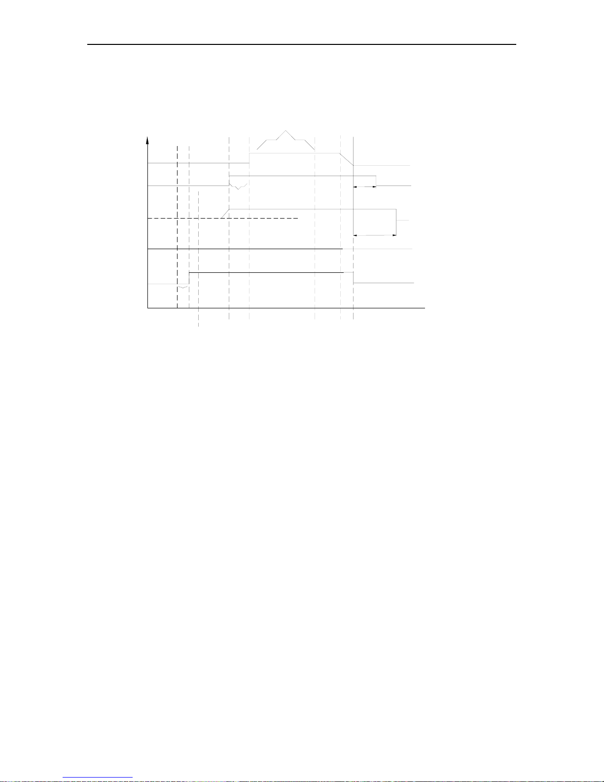
2.4 Defrosting
ON
ON
OFF
ON
Z
Heating/Defrosting Time sequence chart
Defrosting
marking
Defrosting frequency
Compressor
35Hz
Outd oor fa n
Energized
De-energized
Indoor fan
Auxilary power
Defr ostin g
end s
Condition for ending
the defro st
OFF
OFF
Time
Meet the conditions for
ending the defrost
Acc.to the conditions for
starting the auxiliary power
Cold air prevention
Fixed step Y
Adjust according to control logic
High fan
35Hz
Adjust per PI
Acc . to o utdo or fa n co ntro l logic
EXV
4-way valve
10s
3 min
10s
The conditions for starting the defrosting are as follows:
The defrosting is started when one of the following three conditions is satisfied:
The total time for outdoor defrost sensor to run below 3 is longer than 40 minutes and this temperature is kept
lower than -6 for over 3 minutes.
The outdoor temperature sensor keeps lower than 3 ℃ for at least 80 minutes and keeps lower than -4 ℃ for at
least 3 minutes.
The outdoor temperature sensor keeps lower than 3 ℃ for at least 120 minutes and keeps lowers than -3 ℃ for
at least 3 minutes
The conditions for ending the defrosting are as follows:
The defrosting is ended when one of the following three conditions is satisfied:
When the temperature of outdoor heat exchanger rises to higher than 10 .
When the temperature of outdoor heat exchanger rises to higher than 8 and this lasts for over 80 seconds.
When the defrosting keeps for 10 minu tes.
A/A DC INVERTER U-MATCH AIR CONDITIONERS CONTROL
29
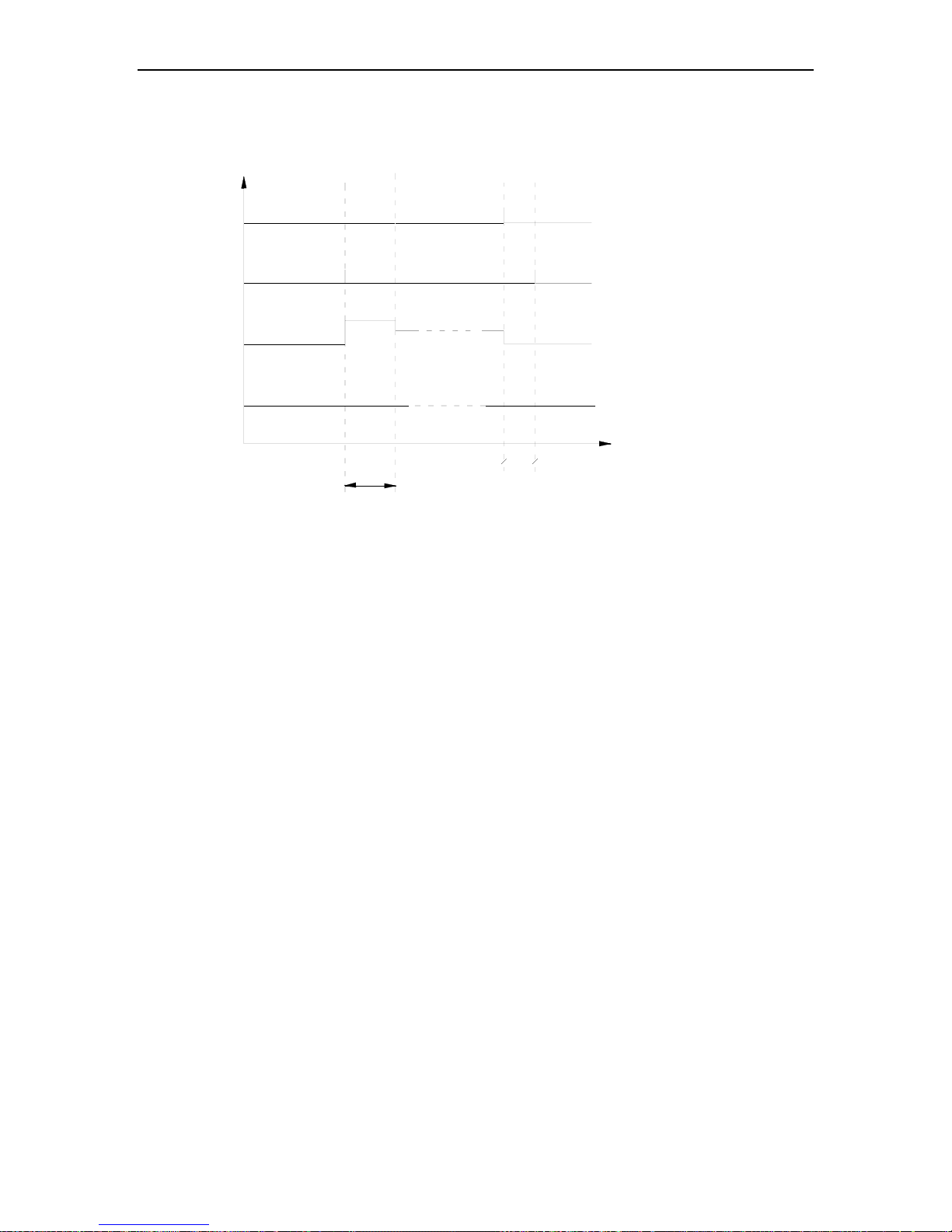
2.5 Fan Mode
Fan Mode
Compressor
Outdoor
fan
4-way valve
Start
Time
Indoor fan
5s
Run at present
speed
Manual speed
OFF
OFF
OFF
OFF
OFF
OFF
High fan
The indoor fan will run at high speed for 5 seconds before running at preset speed
A/A DC INVERTER U-MATCH AIR CONDITIONERS CONTROL
30
3 WIRELESS REMOTE CONTROLLER
3.1 Operation View
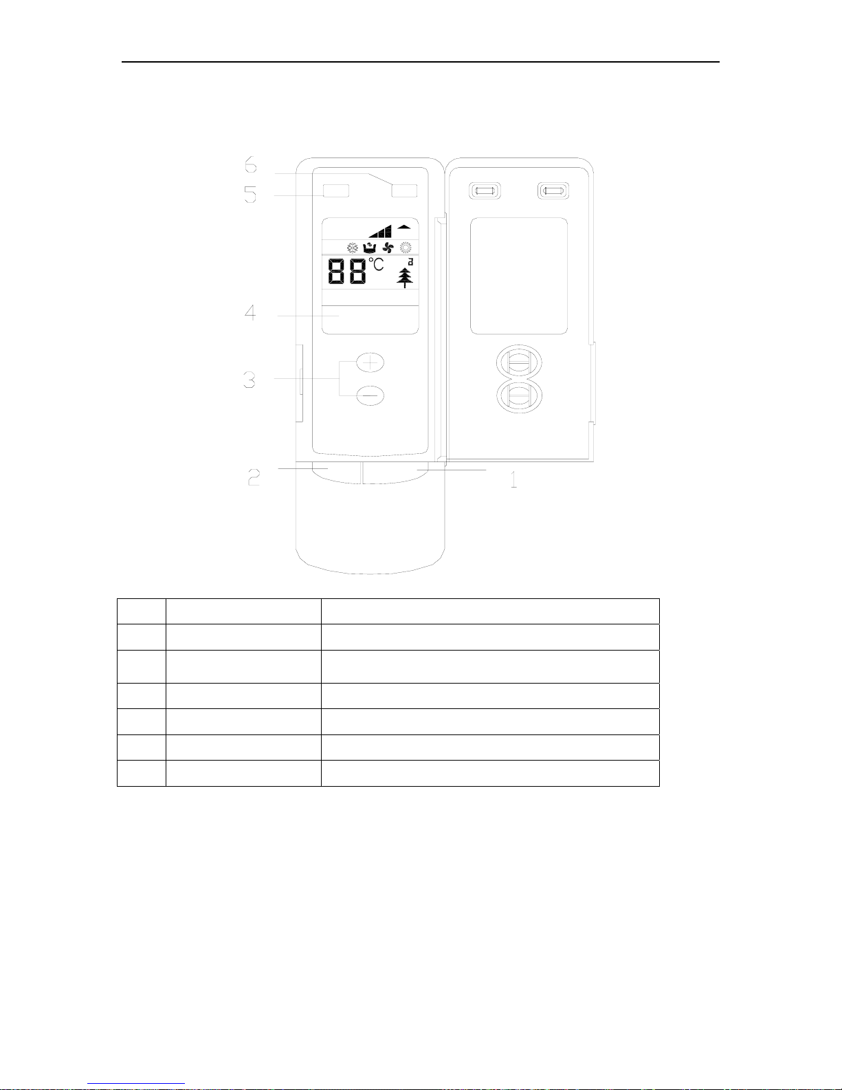
3.1.1 Controller-Duct Type
ON/OFF
MODE
AUTO FAN
SWING
AUTO
SWING
OPER
AIR
FAN
NO. Name Function description
1 ON/OFF button Press the button to set turning on/off the unit
2 Mode button
Press the button to select the mode,
cooling , heating , fan or auto mode.
3 Increase/Decrease button Press this button to increase/decrase the setup temp
4 LCD Screen Display the status of remote information
5 Swing button Press this button set swing function
6 Fan speed button Press this button to set fan speed
A/A DC INVERTER U-MATCH AIR CONDITIONERS CONTROL
31
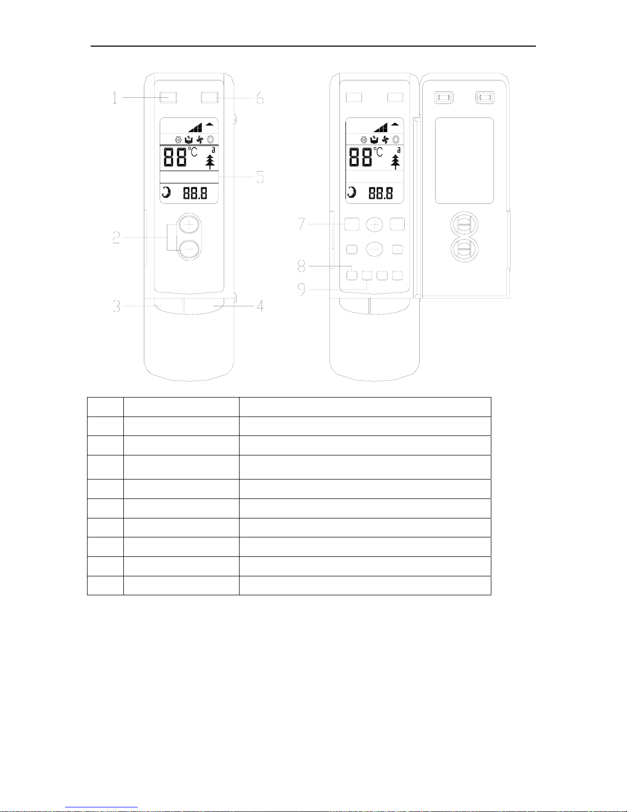
3.1.2 Controller-Cassette Type and Ceiling Type
ON/OFF
MODE
LIGHT
AUTO
TIMER
ON/OFF
SWING HUMID
SWING
Auto Fan
SAVE
HR
AIR
FAN
OPER
TIMER
ON/OFF
ON/OFF
ANION
TIME OFFTIME ON
MODE
LIGHT
SLEEP
SAVE
HUMID
AIR
HR
LIGHT
AUTO FAN
SWING
HUMID
AUTO
SWING
SAVE
OPER
AIR
FAN
NO. Name Function description
1 Swing button Press this button to set swing function
2 Increase/Decrease button Press this button to increase/decrase the setup temp
3 Mode button
Press the button to select the mode,
cooling , heating , fan or auto mode.
4 ON/OFF button Press the button to set start or close unit
5 LCD Screen Display the status of remote information
6 Fan speed button Press this button to set fan speed
7 Sleep button Press the button to set sleep function
8 Time on Press the button to set time on function
9 Time off Press the button to set time off function
A/A DC INVERTER U-MATCH AIR CONDITIONERS CONTROL
32
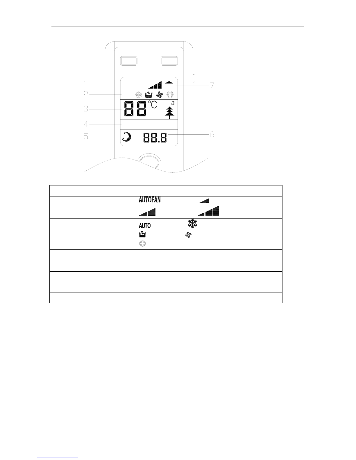
3.2 Display View
LIGHT
AUTO
TIMER
ONOFF
SWING
HUMID
SWING
AUTO FAN
SAVE
HR
AIR
FAN
OPER
No. Display Function description
1 Fan Speed
:auto fan speed, :low fan speed,
:middle fan speed :high fan speed,
2 Run Mode
:Auto running; :Cool running;
:Dry Running; :Fan Running;
:Heat running (Heat and Cool unit only)
3 Setup temp Temperature value of setting
4 Swing function Swing is on
5 Sleep mode Sleep mode is on
6 Time value Timing value of setting
7 OPER The controller is on
A/A DC INVERTER U-MATCH AIR CONDITIONERS CONTROL
33
4 WIRED REMOTE CONTROLLER
4.1 Operation View
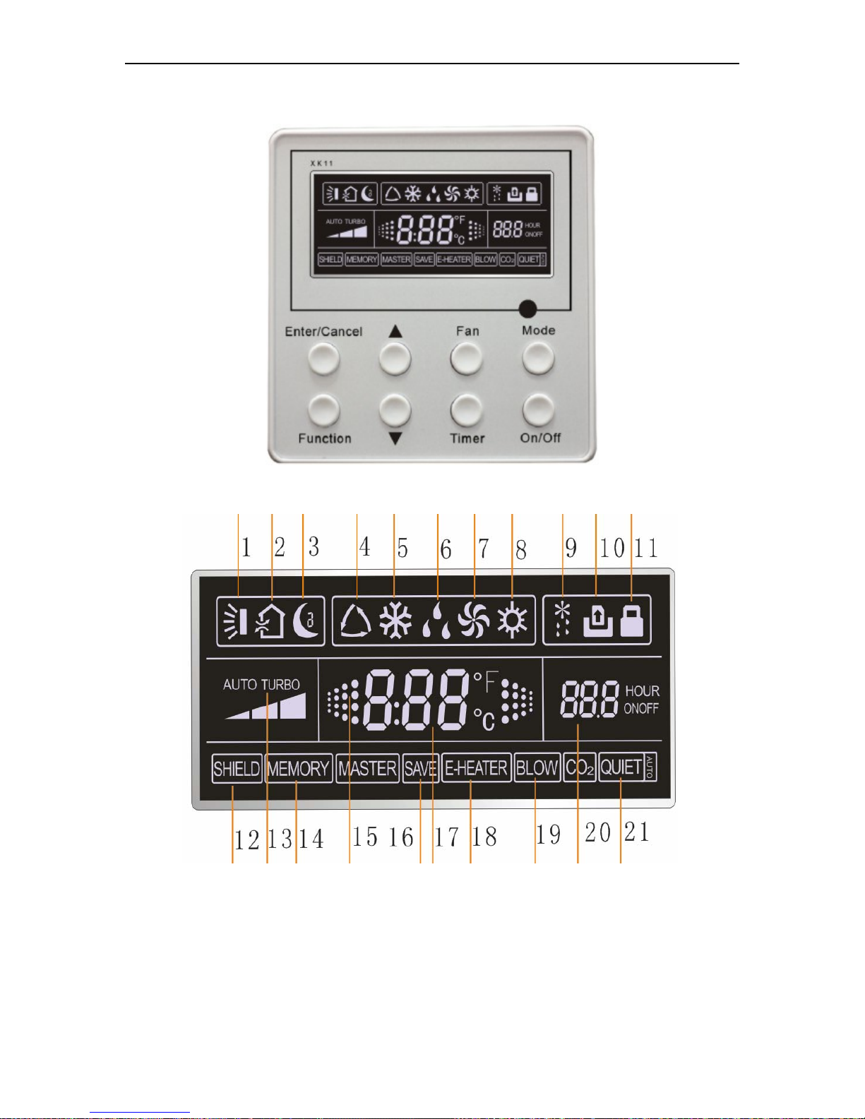
4.1.1 LCD Display of Wired Controller
.
A/A DC INVERTER U-MATCH AIR CONDITIONERS CONTROL
34
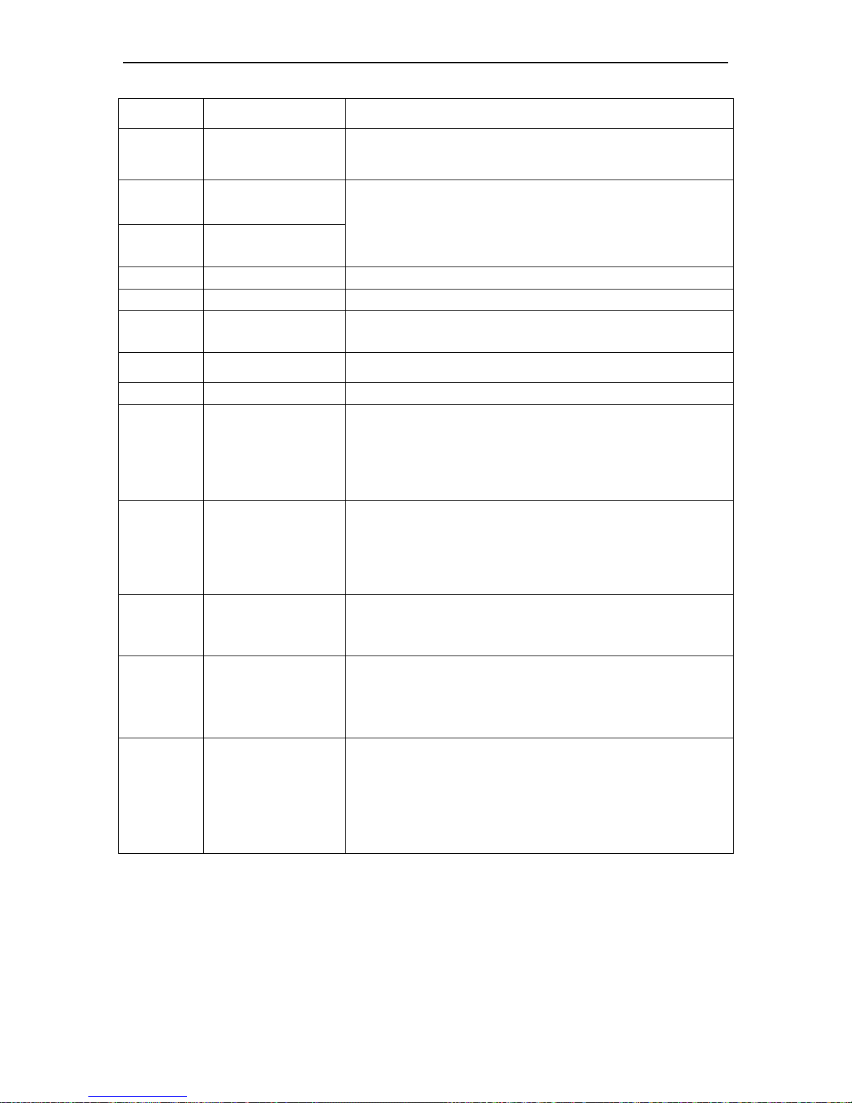
4.1.2 Instruction to LCD Display
No. Description Instruction to Displaying Contents
1 Swing Swing function
2
Air
*
Air exchange function
3 Sleep Sleeping states
4 Running mode Each kind of running mode of indoor unit (auto mode)
5 Cooling Cooling mode
6 Dry Dry mode
7 Fan Fan mode
8 Heating Heating mode
9 Defrost Defrosting state
10
Gate-control
card
*
Gate control
11 Lock Lock state
12 Shield
Shielding state (buttons, temperature, on/off, mode or save is shielded by
long-distance monitoring
13 Turbo Turbo function state
14 Memory
Memory state (Indoor unit resumes original setting state after power failure and then
power recovery)
15 Twinkle Flicking when unit is on without operation of buttons
16 Save Energy-saving state
17 Temperature Ambient/setting temperature value
18
E-Heater
*
Mark that E-heater is allowed to turned on
19 Blow Blow mark
20 Timer Timer-displayed location
21 Quiet Quiet state(two types: quiet and auto quiet)
Notes: The functions with * are reserved for other models and are not applicable for the models
listed in this manual.
Table 4.1
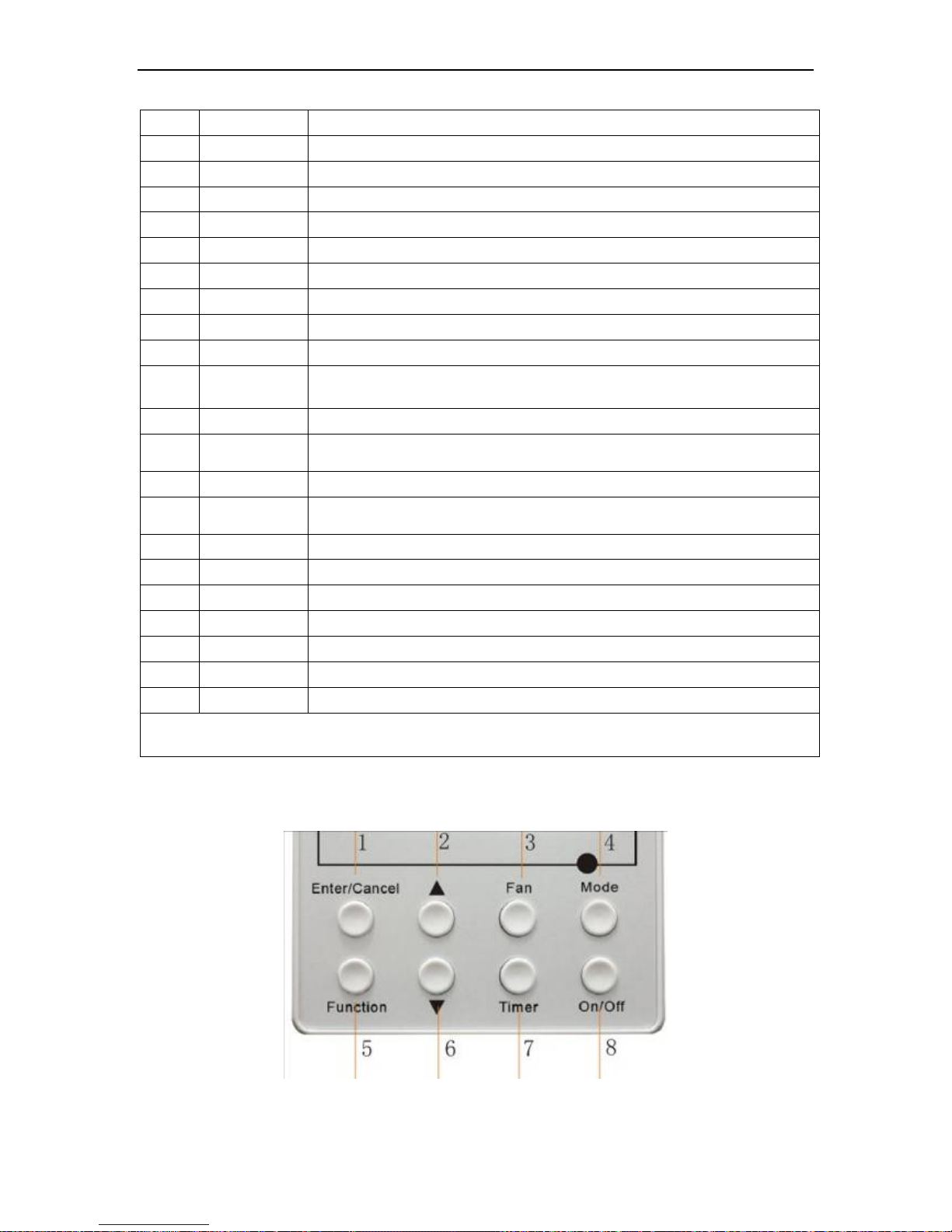
4.2 Buttons
4.2.1 Silk Screen of Buttons
Fig. 4-2-1 Silk screen of butto
A/A DC INVERTER U-MATCH AIR CONDITIONERS CONTROL
35
4.2.2 Instruction to Function of Buttons
No. Description Function of Button
1 Enter/cancel
(1)Function selection and canceling;
(2)Press it for 5s to enquiry the outdoor ambient temperature.
2 ▲
6 ▼
(1)Running temperature setting of indoor unit, range :16~30℃
(2)Timer setting, range:0.5-24hr
(3)Switchover between quiet/auto quiet
3 Fan Setting of high/middle/low/auto fan speed
4 Mode Setting of cooling/heating/fan/dry mode of indoor unit
5 Function
Switch over among these functions of
air/sleep/turbo/save/e-heater/blow /quiet
7 Timer Timer setting
8 On/off Turn on/off indoor unit
4 Mode
and
2 ▲
Memory function
Press Mode and ▲for 5s under off state of the unit to enter/cancel key
memory function (If memory is set, indoor unit will resume original
setting state after power failure and then power recovery. If not, indoor
unit is defaulted to be off after power recovery. Memory function is
defaulted to be off before outgoing.)
2 ▲
and
6 ▼
Lock
Upon startup of the unit without malfunction or under off state of the unit,
press ▲ ▼ key at the same time for 5s in to lock state. In this case, any
other buttons won’t respond the press. Repress ▲ ▼ key for 5s to quit
lock state.
4 Mode
and
5 Function
Enquiry and setting of
address of wired
controller
Under the off-state of the unit, press Mode/Function button for 5
seconds to set the address.
5 Function
And
7Timer
Setting Ambient
Temperature Sensor
and three Grades of
Speed for Indoor Fan
Under off state of the unit, press Function and Timer buttons
continuously for 5s to go to the debugging menu. Press Mode button to
adjust the setting items and ▲ or ▼ button to set the actual value.
5 Function
and
6▼
Enquiry of Historical
Errors
Continuously press Function and ▼ buttons for 5s to go to the enquiry
state. In this state, press Enter/Cancel button to quit, or it will
automatically quit after there is not any operation of button in 30min
A/A DC INVERTER U-MATCH AIR CONDITIONERS CONTROL
36
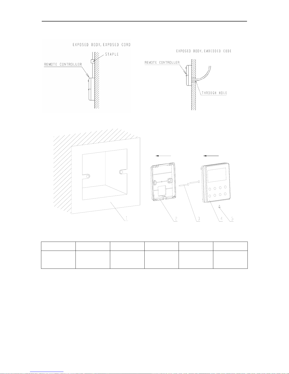
4.3 Installation of Wired Controller and Project Debugging
4.3.1 Installation of Wired Controller
Fig.4.3.1: Fig.1
Surface mounting of Cable Fig.4.3.2: Fig.2 Concealed mounting of Cable
Fig.4.3.3: Sketch for Installation of Wired Controller
No. 1 2 3 4 5
Description
Socket’s base
box installed in
the wall
Soleplate of
controller
Screw M4X25
Front panel of
controller
Screw ST2.2X6.5
Fig.4.3.3: Sketch for Installation of Wired Controller. Pay attention to the following items during installation of wired
controller:
1. Cut off power supply of heavy-current wire embedded in mounting hole in the wall before installation. It is
prohibited to perform the whole procedure with electricity.
2. Pull out 4-core twisted pair line in mounting hole and then make it through the rectangle hole at the back of
controller’s soleplate.
3. Joint the controller’s soleplate on wall face and then fix it in mounting hole with screws M4X25.
4. Insert the 4-core twisted pair line through rectangle hole into controller’s slot and buckle the front panel and
soleplate of controller together.
5. At last, fix the controller’s front panel and soleplate with screws ST2.2X6.5.
A/A DC INVERTER U-MATCH AIR CONDITIONERS CONTROL
37
Caution:
During connection of wirings, pay special attention to the following items to avoid interference of electromagnetism
to unit and even failure of it.
1. To ensure normal communication of the unit, signal line and wiring (communication) of wired controller should be
separate from power cord and indoor/outdoor connection lines. The distance between them should be kept 20cm
in min.
2. If the unit is installed at the place where there is interference of electromagnetism, signal line and wiring
(communication) of wired controller must be shielded by twisted pair lines.
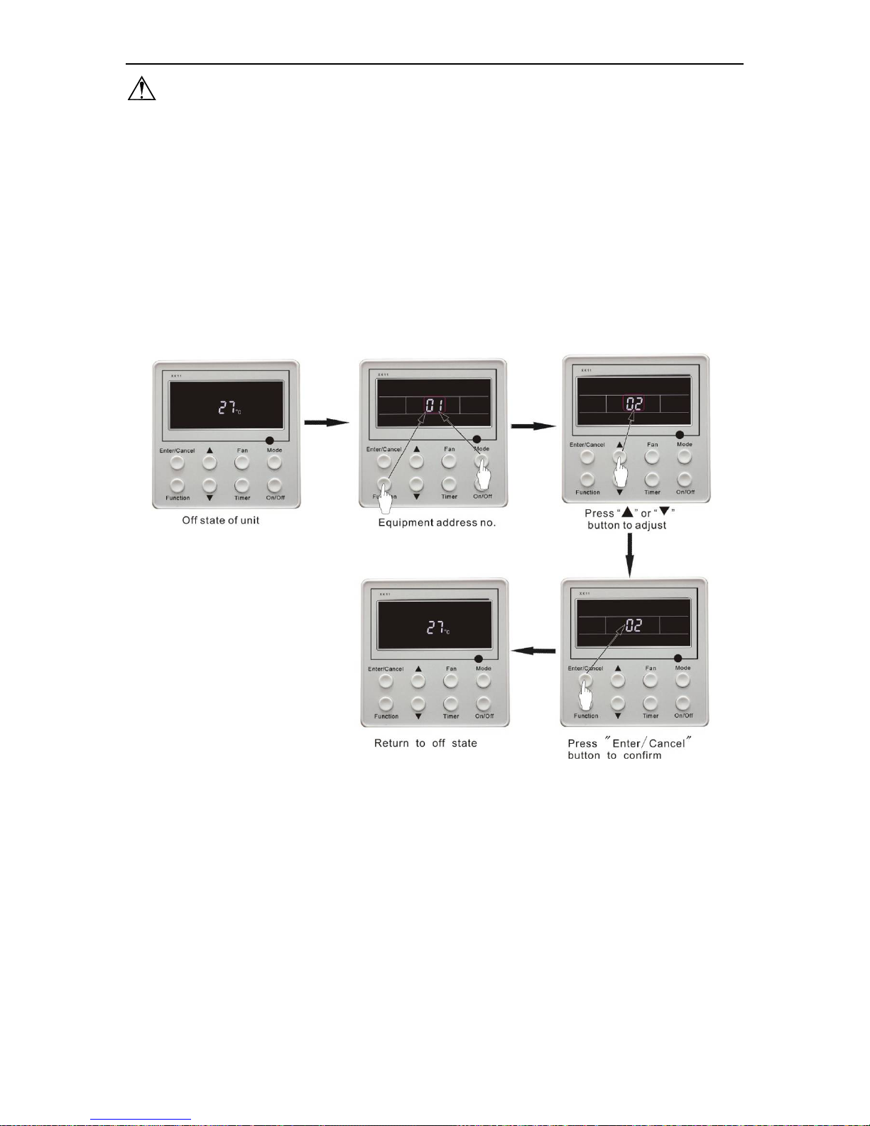
4.3.2 Project Debugging
Enquiry of wired controller’s address: Press Function and Mode buttons at the same time for 5s under off state
of the unit, and then LCD displays wired controller’s address number.
Setting of wired controller’s address: Press Function and Mode buttons at the same time for 5s.In this case,
LCD displays address number. Then press ▲ or ▼ button to adjust address (address no.:1-16) .After that, press
Enter/cancel button to confirm.
Addresses of the wired controller are used for centralized control of wired controller. Enquiry and setting of
wired controller’s address is shown as Fig.4.3.4 below:
Fig.4.3.4: Enquiry and Setting of Wired Controller’s Address
 Loading...