

Vivax Easy Locator Operator's Manual
www.vivax.it
19-001011
Easy Locator
Operator’s Manual
Version 1.6

www.malags.com
2
Table of Contents
_________________________________________________
1 Introduction 3
1.1 Unpacking and Inspection 4
1.2 Repacking and Shipping 4
1.3 Important information regarding the use of this GPR unit 4
2 System Startup 5
2.1 Hardware Assembly 5
2.2 Cable Connections and Startup 7
2.3 Start up and Power buttons 9
2.4 Changing antennas 10
2.5 Adjustable wheels 11
3 System operation 12
3.1 Monitor Operation 12
3.2 System settings 12
3.3 Start 15
3.4 Stop 15
3.5 Full screen 16
3.6 Filter 16
3.7 Save image (only for the IXM monitor) 16
3.8 Quit 18
4 Using the Easy Locator 19
5 Data examples and Interpretation 21
6 Batteries 25
7 Trouble shooting 27
8 Technical Specification 28

www.malags.com
3
1 Introduction
__________________________________________________
Thank you for purchasing the Easy Locator. The Easy Locator is a Ground
Penetrating Radar (GPR) that can detect metallic as well as non-metallic
objects in the ground. GPR are in many cases the only non-intrusive
method to detect and designate the location of e.g. non-metallic utilities
such as plastic or concrete, where standard locating technology cannot
provide the complete picture.
The Easy Locator is available with two different models of monitors, the
EXM and the IXM. The IXM monitor enables saving screen dumps of the
radargram (as *.jpg-images), which can be uploaded for documentation.
The EXM and IXM are equipped with a High Bright screen, but also
available in a +-option, giving you a Transflective screen for best
performance in bright daylight.
We at Malå GeoScience welcome comments from you concerning your use
and experience with our products, as well as the contents and usefulness
of this manual. Please take the time to read through the assembling
instructions carefully and address any questions or suggestions to us at the
following addresses:
Main Office: North & South America: Asia/Pacific:
Malå GeoScience Malå GeoScience USA, Inc. MALÅ GeoScience
Skolgatan 11 2040 Savage Rd, P.O. Box 80430 23-1b, Jalan 26/70a
S-930 70 Malå Charleston, SC 29416 Desa Sri Hartamas
Sweden USA 50480 Kuala Lumpur
Phone: +46 953 345 50 Phone: +1-843 852 5021 Malaysia
Fax: +46 953 345 67 Fax: +1-843 769 7397 Phone: +60 32300 1086
E-mail: sales@malags.se E-mail: sales.usa@malags.se Fax: +60 32300 0956
E-mail: bwr@malags.se
Technical support issues can be sent to: support@malags.se
Information about the products from MALÅ GeoScience is also available on Internet:
http://www.malags.com

www.malags.com
4
1.1 Unpacking and Inspection
Great care should be taken when unpacking the equipment. Be sure to
verify the contents shown on the packing list and inspect the equipment for
any loose parts or other damage. All packing material should be kept in the
event that any damage occurred during shipping. Any claims for shipping
damage should be filed to the carrier. Any claims for missing equipment or
parts should be filed with Malå GeoScience.
Note! Three serial numbers are attached, on the backside of the monitor,
under the control unit and on top of the antenna.
1.2 Repacking and Shipping
If original packing materials are unavailable, the equipment should be
packed with at least 80 mm of absorbing material. Do not use shredded
fibres, paper wood, or wool, as these materials tend to get compacted
during shipment and permit the instruments to move around inside the
package.
1.3 Important information regarding the use of
this GPR unit
According to the regulations stated in ETSI EN 302 066-1 (European
Telecommunication Standards Institute):
- The control unit should not be left ON when leaving the system
unintended. It should always be turned OFF when not in use.
- The antennas should point towards the ground, walls etc. during
measurement and not towards the air.
- The antennas should be kept in close proximity to the media under
investigation
www.malags.com
5
2 System Startup
_______________________________________________________
The Easy Locator is a system with an integrated but modular control unit
and monitor. The control unit is mounted directly to the antenna and
powered internally. It is compatible with both Easy Locator antennas “Mid”
and “Shallow”. See Chapter Changing antennas for more information.
The monitor (EXM or IXM) mounts on the handle and can be moved for use
on either antenna choices, either by transferring the monitor only or by
transferring the handle, shafts, battery box and the monitor as one unit.
The system will automatically detect the selected antenna and default to
the appropriate data collection settings.
2.1 Hardware Assembly
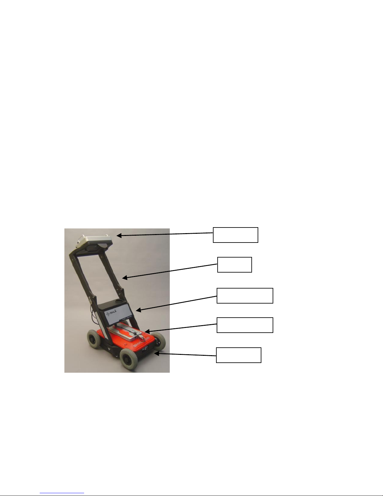
The complete Easy Locator system is seen in Figure 2.1.
Fig. 2.1 An Easy Locator with all its parts; monitor, control unit and
antenna.
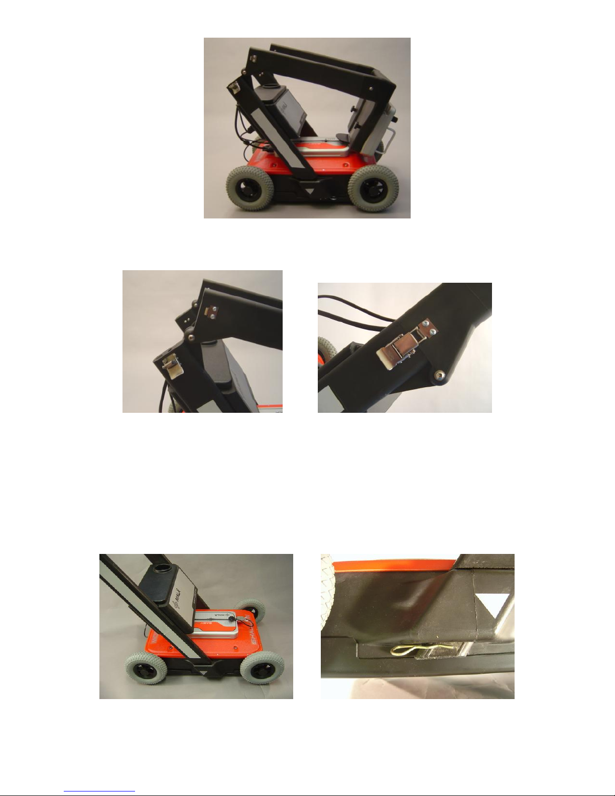
2.1.1 Mounting the shafts
When delivered the Easy Locator has it handles mounted and folded, as in
Figure 2.2. In this way your equipment is quit handy to move and pack. By
just securing the locks in Figure 2.3 the system is ready to use.
Monitor
Shaft
Battery box
Control unit
Antenna
www.malags.com
6
Fig.2.2 The Easy Locator with folded shafts.
Fig.2.3 The foldable shafts unlocked (left) and locked (right).
When changing antennas or otherwise dismounting the shaft, this is best
done with the foldable shaft in an up-right position.
Insert the shafts with monitor and battery box into the slots on the antenna
and secure with pins (Figure2.4).
Fig.2.4 Left: Shaft mounted to the antenna. Right: Securing pins.
www.malags.com
7
2.1.2 Mounting the monitor
The monitor can be mounted or removed from the handle by using the two
screws beneath the handle. The monitor is also secured by Velcro strips.
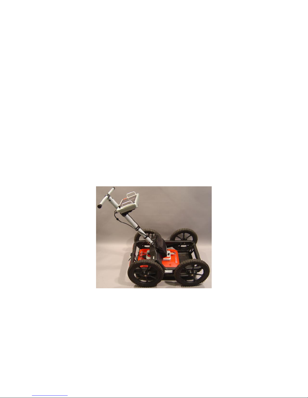
2.1.3 Mounting the EasyLocator in an RTC (Rough
Terrain Cart)
The EasyLocator antenna, control unit and monitor can also be used
together with Malå´s Rough Terrain Cart, the RTC, which increases the
operational capabilities in a more rugged terrain.
In Figure 2.5 the EasyLocator system with the RTC is seen. The antenna is
dismounted from the EasyLocator shafts (see above) and then the antenna
is placed on the RTC antenna tray. This is self-adjustable to ensure that the
antenna stays in contact with the ground for optimal signal performance.
The monitor is mounted on the RTC handle with the same screws used on
the EasyLocator handle.
Fig.2.5. The EasyLocator antenna, control unit and monitor on a RTC.
2.2 Cable Connections and Startup
2.2.1 Connecting cables to the monitor
Connect the Ethernet communication cable to the monitor and use the
cable supplied or a crossover RJ-45 cable.
www.malags.com
8
Also connect the power cable to the monitor. Use the standard cable
supplied. See Figure 2.5.
Look for the countersink in the power cable and place it towards the mark
on the connection. Push lightly. If you have it in the correct position it will go
in its position smoothly. To disconnect: Pull out, holding the metal part of
the connection.
Fig. 2.5 Connections on the monitor; to the left, the Ethernet cable and to
the right, the power cable.
Connect the power cable to one of the identical outlets in the battery box
(Figure 2.6). If a RTC is used the power cable is connected to the battery
pack on the RTC, see Chapter Batteries.
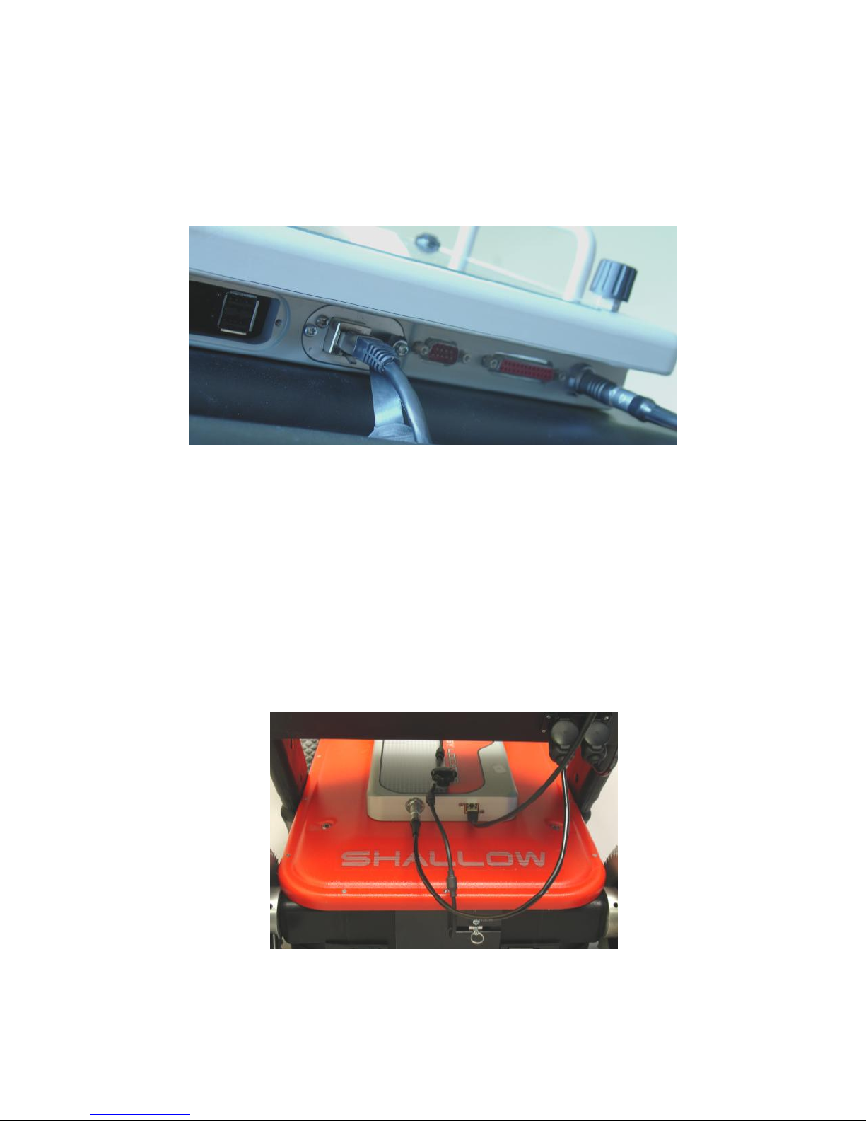
2.2.2 Connecting cables to the control unit
Connect Ethernet and power cables to the control unit (Figure 2.6)
Fig. 2.6. The connections to the control unit; left is power and right is
Ethernet communication cable. Above right the connections to the battery
box is seen.
www.malags.com
9
Connect the power cable to the other outlet in the battery box (Figure 2.6).
If a RTC is used the power cable is connected to the battery pack on the
RTC, see Chapter Batteries.
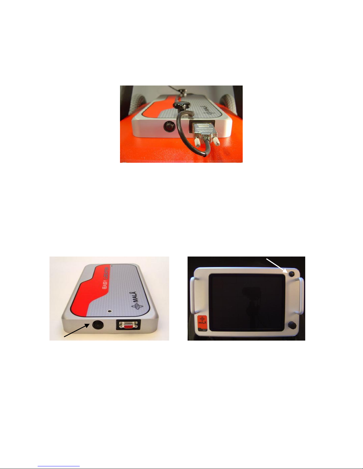
Finally, connect the encoder cable to the control unit (Figure 2.7).
Fig. 2.7. Encoder cable to the control unit.
2.3 Start up and Power buttons
Start the Easy Locator by pressing the start button on both the control unit
and the monitor (Figure 2.8). The light in the centre of the button on the
control unit will start to blink. During the measurement the button will
remain illuminated continuously.
Fig 2.8. Start button on the control unit (left) and the monitor (right)
To turn the Easy Locator off, push the button and release quickly. The red
light will then stop blinking and the unit will be turned off with a click sound.
If the power cable is accidentally pulled out the Easy Locator will start
automatically when connected.
www.malags.com
10
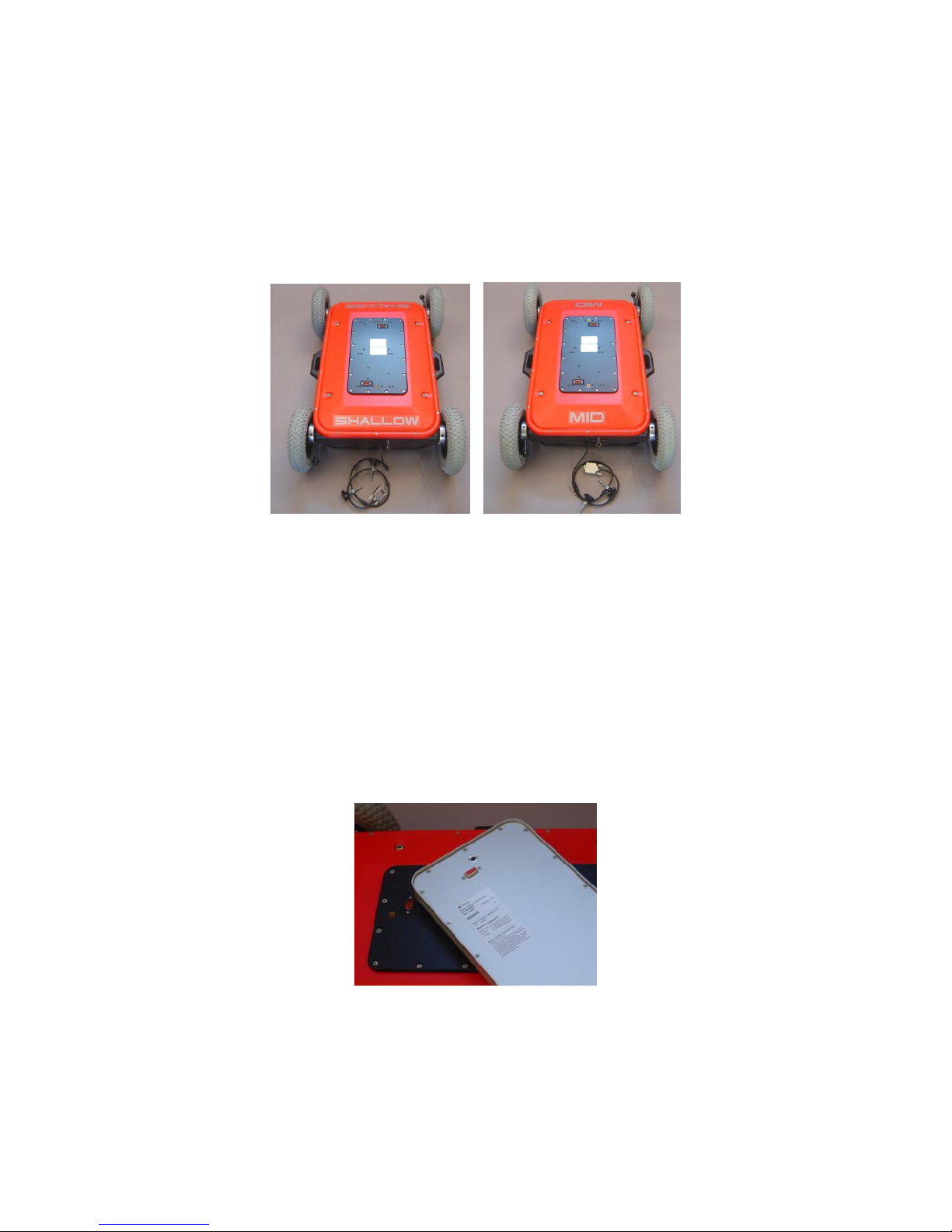
2.4 Changing antennas
Depending on the soil conditions and/or the depth penetration required two
choices of antennas are available, “Shallow” and “Mid”. See Fig. 2.9. The
“Shallow” antenna has a depth penetration of approx. 2.5 m and detects
targets with a size of approx 3 cm in diameter. The corresponding figures
for the “Mid” antenna are 4 m and 5 cm.
Fig. 2.9. Shallow and Mid antennas
To change the antenna, remove the monitor with handle, shafts, and
battery box as well as the control unit. Pull out all cables and the pins
securing the shafts. Change the antenna unit and re-connect all parts back
to original state.
When remounting the control unit be sure to see that it is in the right
direction. See Fig 2.10. There is a slight difference in distance from the
centre between the two connectors.
Fig. 2.10. Backside of the control unit showing one of the two connectors
that should be fitted on the antenna unit.
When the Easy Locator is turned on the control unit will automatically
calibrate to the antenna it is attached to, provided that they are factory
 Loading...