

Vivax ACP-56COFM164GEEI, ACP-48COFM140GEEI User Manual

Upute za uporabu
User manual
ACP-56COFM164GEEI
ACP-48COFM140GEEI
RoHS
14

ENG
User
manual
RoHS
14
ACP-56COFM164GEEI
ACP-48COFM140GEEI
1
Preface
Super Free Match Series Systems adopt the advanced manufacturing technology and takes
the environmental-friendly R410A as refrigerant, which is a green product in the 21st century.
Please carefully read the manual before installation and operation.
♦ The total capacity of the indoor units which runs at the same time cannot exceed the capacity
of the outdoor units; otherwise, the cooling (heating) effect of each indoor unit would be poor.
♦ Make sure that the manual is kept by the operators or serviceman.
♦ The refrigerant pipes and accessories must be designed exclusively for R41 OA.
♦ It is a normal phenomenon that the indoor unit fan will still run for 20~70 seconds after the
indoor unit receives the "stop" signal so as to make full use of the waste heat.
♦ When the work mode of the indoors is conflict with the modes of outdoor units, it will be
indicated on the display of the wired controller in five seconds and then the indoor unit will
stop. In this case, please harmonize their work modes: the cooling mode is compatible with
the dehumidifying mode and the fan mode can go with any other mode. If the supply power
fails when the unit is running, then the indoor unit will send the "start" signal to the outdoor
unit three minutes later after the power recovery.
♦ The power cable and transmission line must not be twisted together, but instead of separated
with an interval of at least 2cm; otherwise it may be result in communication problem.
♦ This appliance is not intended for use by persons (including children) with reduced physical,
sensory or mental capabilities, or lack of experience and knowledge, unless they have been
given supervision or instruction concerning use of the appliance by a person responsible for
their safety. Children should be supervised to ensure that they do not play with the appliance.
♦ Cautions for the debugging and maintenance personnel:
During debugging and maintenance, before the startup of the compressor, it makes sure that
the heater belt of the compressor has been energized for at least eight hours! Once the
compressor is started, it must be guaranteed that it works continuously for at least 30 minutes,
otherwise it would be damaged!
This product must not be disposed together with the domestic waste. This product
has to be disposed at an authorized place for recycling of electrical and electronic
appliances.

2
Contents
1 Safety Precautions ............................................................................................................. 1
2 Attention for Installation ..................................................................................................... 3
2.1 Precautions for R410A ........................................................................................... 3
2.2 Precaution for Installation ....................................................................................... 3
2.3 Precaution for Operation Test ................................................................................ 3
2.4 Accessories ............................................................................................................ 3
3 Product Introduction ........................................................................................................... 4
3.1 Names of Main Parts .............................................................................................. 4
3.2 Combinations for Outdoor and Indoor Units ........................................................... 5
3.3 Parts and Components of Unit ............................................................................... 5
3.4 Working Temperature Range ................................................................................. 6
4 Selection of Installation Location and Precautions ............................................................ 7
4.1 Selection of Installation Location ............................................................................ 7
4.2 Outline Dimension of Outdoor Unit ........................................................................ 8
4.3 Installation and Servicing Space ............................................................................ 9
5 Installation Instruction ...................................................................................................... 10
6 Installation of Refrigerant Pipes ....................................................................................... 11
6.1 Manifold Mode of Connecting Pipe ............................................................................. 11
6.2 Allowable Length and Drop Height of Connecting Pipe ....................................... 13
6.3 Dimension of Connecting Pipe ............................................................................. 14
6.4 Connection of Branch Pipe ................................................................................... 14
6.5 Precaution for Connection .................................................................................... 15
6.6 Connection of Refrigerant Pipe ........................................................................................ 16
6.7 Leak Test ........................................................................................................................ 17
6.8 Vacuum Operation ................................................................................................ 18
6.9 Refrigerant Charging ..................................................................................................... 18
7 Electrical Wiring Work ...................................................................................................... 22
7.1 Wiring Connection ......................................................................................................... 22
7.2 Requirements of Power Circuit and Cable ............................................................... 22
7.3 Ground Requirements ................................................................................................. 23
7.4 Precautions on the Electrical Wiring Work ............................................................... 23
7.5 Precaution of Laying Wires .......................................................................................... 24
7.6 Procedures for Electrical Wiring Work ........................................................................ 24
8 Design of Drainage Pipeline ............................................................................................ 25
8.1 Installation of Drain Hose ............................................................................................. 25
8.2 Design of Drainage Pipeline ................................................................................. 25
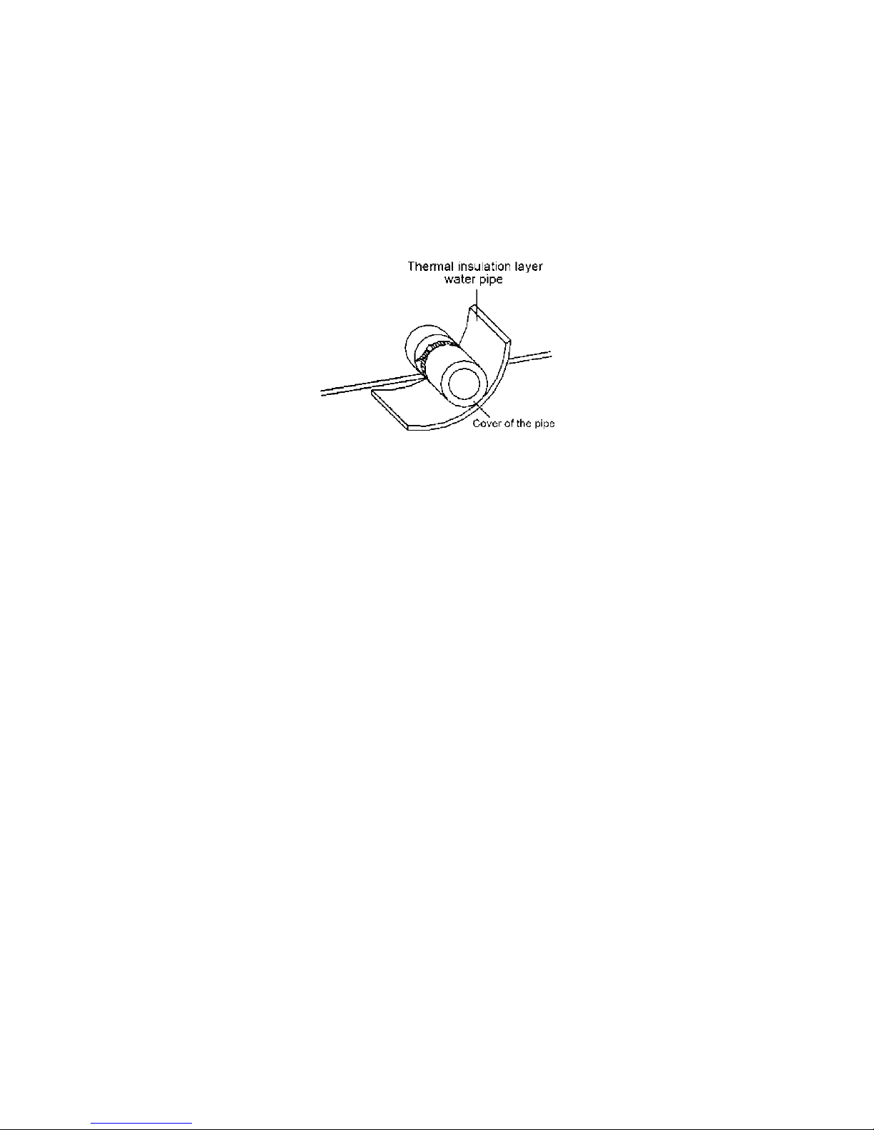
9 Installation of Protective Layer on Connection Pipe ........................................................ 26
10 Test Operation ................................................................................................................. 27
10.1 Check after Installation ................................................................................................ 27
10.2 Test Operation ................................................................................................................ 27
11 Testing Board Introduction ........................................................................................................ 28
11.1 Compose of the Testing Board ............................................................................. 28

3
11.2 Instruction of Function and Data Section .............................................................. 28
12 Troubleshooting ............................................................................................................... 29
12.1 Check before Contacting Service Center ............................................................. 29
12.2 Problem Handling ................................................................................................. 30
12.3 Error Description ................................................................................................... 30
12.4 After-Sales Service ............................................................................................... 34
13 Maintenance .................................................................................................................... 35
13.1 Outdoor Heat Exchanger ...................................................................................... 35
13.2 Drain Pipe ....................................................................................................................... 35
13.3 Check before the Seasonal Use ................................................................................ 35
13.4 Maintenance after Seasonal Use ......................................................................... 35
14 After-sales Service ........................................................................................................... 36

1
1 Safety Precautions
♦ Please read this manual carefully to ensure correct installation as instructed in the manual.
♦ Please especially take notice of the following two symbols:
Warning!: It indicates improper operation which will lead to human casualty or severe
injury.
Caution!: It indicates improper operation which will lead to injury or property damage.
Warning !
The installation should be left to the appointed service center. Otherwise, it maybe cause
water leakage, electric shocks or fire etc.
Please install the air conditioner according to the instructions given in the manual. Improper
installation may cause fall down, water leakage, electric shock or fire etc.
Please install the unit on a solid place where is strong enough to support the weight of the unit.
Otherwise, the unit would fall down and cause injury or death.
Please keep the room well-ventilated and it could avoid oxygen deficit.
Electrical work should be carried out in accordance with the installation manual and the local
laws and regulations. Insufficient capacity or incomplete electrical work may cause electrical
shock or fire etc.
The power supply must adopt the special circuit with air switch protection and assure it has
enough capacity. The unit will be turned on or off according to your requirement automatically,
please do not turn on or off the unit frequently. Otherwise disadvantage effect may be caused to
the unit.
Never cut off or damage power cables and control wires. If the power cable and signal control
wire were damaged, change them by professional.
The electrical work should use a cable length enough to cover the entire distance with no
connection. If it is unavoidable, please make sure the connection should be reliable and the
external forces will not act on the wires. Otherwise it will cause electrical shock or fire etc.
When having a burning smell or smoke, please turn off the power supply and contact with the
service center.
Don't attempt to repair the air conditioner by yourself. The wrong repair will lead to an electric
shock or fire, so you should contact the service center to repair.
Do not use or store flammable, explosive, poisonous or other dangerous substances beside
the air conditioner.
When installing or relocating the unit. Please contact the appointed service center or the
professional installation personnel for the repair or relocation of the unit.
Rated voltage of this air conditioner is 380V,50Hz.The compressor will vibrate sharply if the
voltage is too low and damage the refrigerating system.Electrical component are easy to damage
if the voltage is too high. The voltage should be stable; there shouldn't be big fluctuation.
Never insert the finger or any other object into the air outlet/inlet grille.
2
Please take notice of the installation foundation of the unit after long use, if it is damaged, it
may lead to the fall of the unit and cause the injury.
The refrigerant pipes and accessories must be designed exclusively for R410A.
Caution!
Before installation, please check that whether the power supply corresponds with the
requirement specified on the nameplate and also check its security.
Before using the unit, please check the piping and wiring, ensure they are correct to avoid
water leakage, refrigerant leakage, electric shock, or fire etc.
Ground connection: connect to the ground reliably! The ground wire should be connected to
the appropriative grounding device of the building. If the appropriative grounding device is not
available, please ask a professional to install. Never connect the ground wire to gas pipe, water
pipe, lightning rod, telephone line or other unreliable places considered by a professional.
It must install an earth leakage breaker. Otherwise, it maybe cause electric shocks or fire etc.
Install the air conditioner, the power wire and transmission line must be more than one meter
away from televisions or radios which can emit electromagnetic waves to prevent image
interference or noise. Otherwise, the unit maybe cannot work.
The drain pipe should be installed as instructed in the manual to guarantee the proper
drainage; meanwhile it should be insulated to prevent condensing; otherwise the improper
installation would cause water leakage and then wet the household wares in the room.
Be sure to shut off the power supply when you do not use the air conditioner for a long time.
Otherwise, the dusts may accumulate in it, which may cause overheating or fire hazards.
Never standing on the outdoor unit or place objects on it. Person or objects falling from the
unit may cause injury.
The air conditioner is not support to install in the circumstances as the following that where
there is full of mist of oil, corrosive gas, flammable gases, the acidic or alkaline vapor and the
ocean.
Once started, the air conditioner shall not be stopped at least after 5 minutes or longer; otherwise
its service life the unit will be shortened.
Do not let the children operate the air conditioner.
Never operate the unit with wet hands. Otherwise, it may cause electric shock.
Before cleaning and repairing, it is necessary to stop working and turn off the power supply.
Otherwise, it may cause electric shock or damage.
It is suggested to have a power-on test annually.

3
2 Attention for Installation
2.1 Precautions for R410A
♦ It is very strict that the refrigerant pipes should be clean and dry.
♦ The R410A is a mixed refrigerant, when add the refrigerant to the unit, it must keep the
refrigerant in its liquid state. If the refrigerant is in gas state, the composition has been
changed and the capability of the unit will decrease.
♦ When the refrigerant is leak out, please do not touch the leakage. Otherwise, it will result in
frostbite.
♦ It does not support to let a lot of refrigerant go into the ambient atmosphere, because it will
strengthen the green house effect. Otherwise, it will produce toxic gas when the refrigerant
contacts with the fire.
2.2 Precaution for Installation
♦ The unit is so heavy that it is more than 110kg, so more than two persons will be needed to
remove the unit. The package cannot bear it, so do not grasping it.
♦ When remove the units, please place the hands on the corner and take care not to hurt the
hands by the fins.
♦ It is very likely to dispose the waste to the garbage bin after the installation.
2.3 Precaution for Operation Test
In order to protect the compressor from vibrating during transportation and 2 metal gaskets are
used. They must be removed prior to commissioning and tied back the nut firmly; otherwise the
unit might not be operated well.
2.4 Accessories
The accessories of the unit, please look out the Packing List in the package.
4
3 Product Introduction
The VIVAX Super Free Match System adopts inverter compressor technology. According to
change displacement of compressor, stepless capacity regulation within range of 10%~ 100% can be
realized. Various product line-up is provided with capacity range from 14kW to 16kW, which can be
widely used in commercial, business office and especially applicable to the place with variable load
change. VIVAX commercial air conditioner is absolutely your best choice.
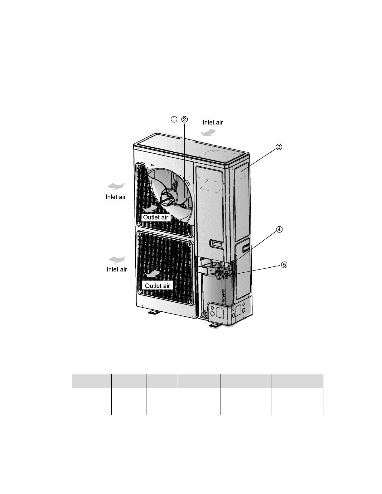
3.1 Names of Main Parts
NO.
① ② ③ ④ ⑤
Name
Fan
Motor
Axial
Flow Fan
Electric Box
Assy
Gas valve
assembly
Liquid valve
assembly
Fig. 1
5
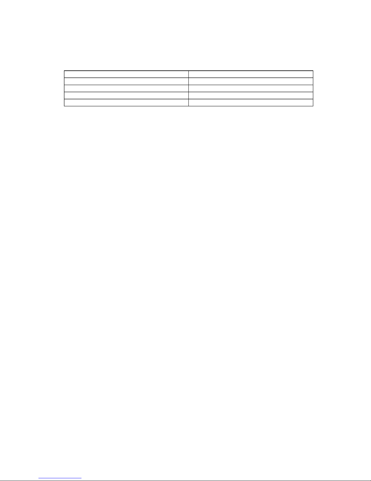
3.2 Combinations for Outdoor and Indoor Units
Table 1
Sorts
ACP-48COFM140GEEI
ACP-56COFM164GEEI
No. of indoor units
to be connected
Min
2
2
Max
8
9
Total capacity
of indoor units to be
connected(Btu/h)
Min
24000
28000
Max
64000
72000
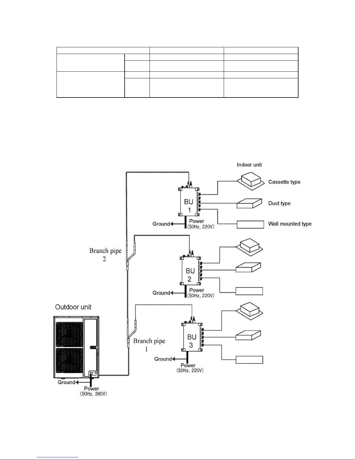
3.3 Parts and Components of Unit
For the super free match series system, one outdoor unit is able to drive up to three BU modules
and nine indoor units which include cassette type, duct type, wall mounted type. The outdoor unit will
run as long as any one indoor unit receives the running command,and all indoorunits stop once the
outdoor unit is turned off.
Fig. 2
6
3.4 Working Temperature Range
Sorts
Outside temperature DB/WB(°C)
Maximum cooling
48/-
Minimum cooling
10/-
Maximum heating
27/-
Minimum heating
-15/-
Table 2

7
4 Selection of Installation Location and Precautions
Caution!
♦ The installation of the air conditioner must be in accordance with the national and local laws
and regulations.
♦ The quality of the installation will affect the capability of air conditioner directly. The
installation should be left to the appointed service center. Please contact your dealer after
purchasing this machine. Professional installation workers will provide installation and test
services according to the installation manual.
♦ The air conditioner should not install in this place where the small animals exist, because
they may cause malfunctions, smoke or fire. Please keep the area around the unit clean.
4.1 Selection of Installation Location
♦ The outdoor unit must be installed on a firm and solid support which can withstand the weight
and the mounting surface must be horizontal plane.
♦ There is enough space for the installation and maintenance.
♦ The place should be well-ventilated, so the machine can absorb and discharge sufficient air.
♦ Outdoor unit shall be installed close to the indoor unit, hence to minimize the length and
bends of cooling pipe.
♦ Avoid place the outdoor unit under the windows or between the constructions, hence to
prevent normal operating noise from entering the room.
♦ Do not install in the place where there is flammable or explosive gas exist or a place subject
to severe dust, salty fog and polluted air.
Caution!
Installation at the following places might lead to the air conditioner malfunction. If it is unavoidable,
please contact the appointed service center.
♦ A place which is full of machine oil;
♦ A region with saline-sodic soil near the sea;
♦ A place where the sulphide fog exists, such as the sulphur spring;
♦ A place where the high frequency facilities exist, such as radio equipment, electric welder
and medical equipment;
♦ An environment with special conditions.
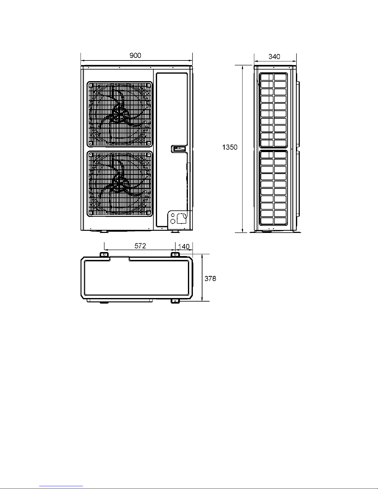
8
4.2 Outline Dimension of Outdoor Unit
Fig. 3 (mm)
9
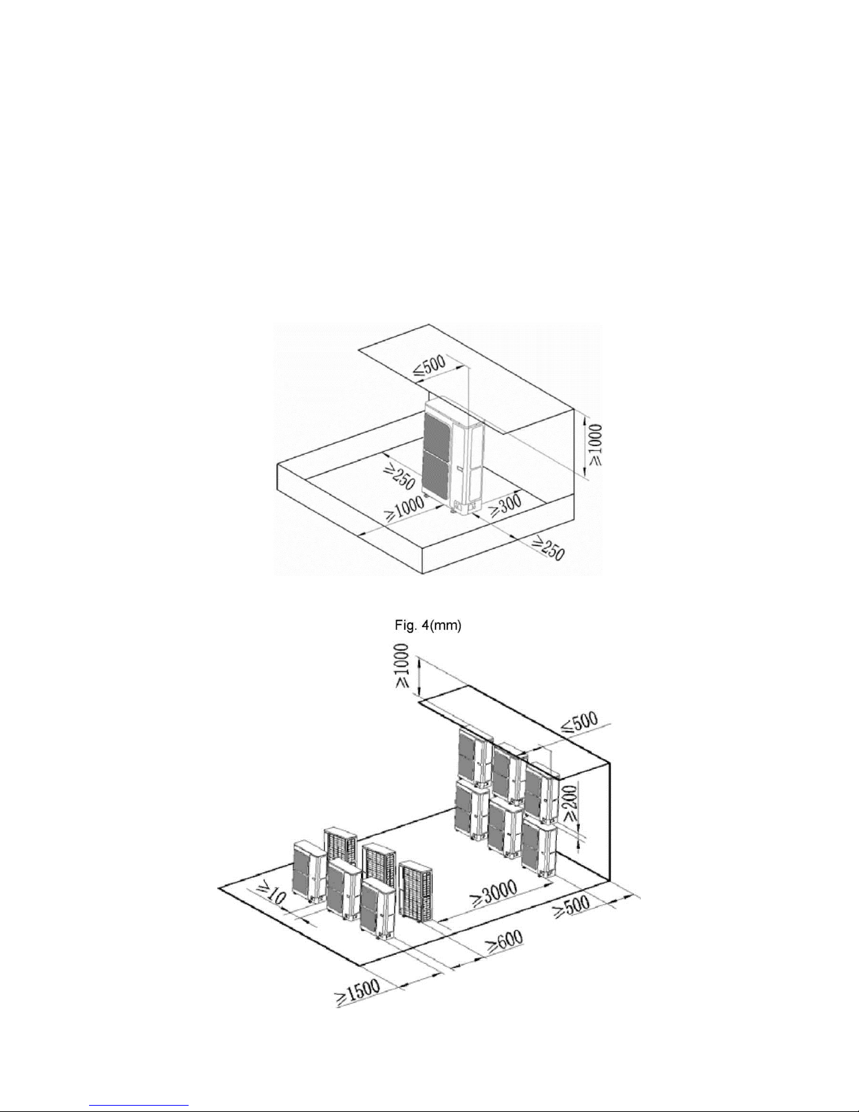
4.3 Installation and Servicing Space
1) When the place of the installation is exposed to strong wind
When strong winds of 5 m/sec or more exist in the place of the installation, the outlet of the unit
cannot face the wind. If the wind blows against the outdoor unit's air outlet, it will cause
deterioration of the operational capacity and maybe break the fan.
2) In case of installing only one unit
In case obstacles exist around the unit, the required installation space is in the Fig. 4.
3) In case of installing multiple units(2 units or more)
In case multiple rows of series installation, the required installation space is in the Fig. 5.
Fig. 5
10
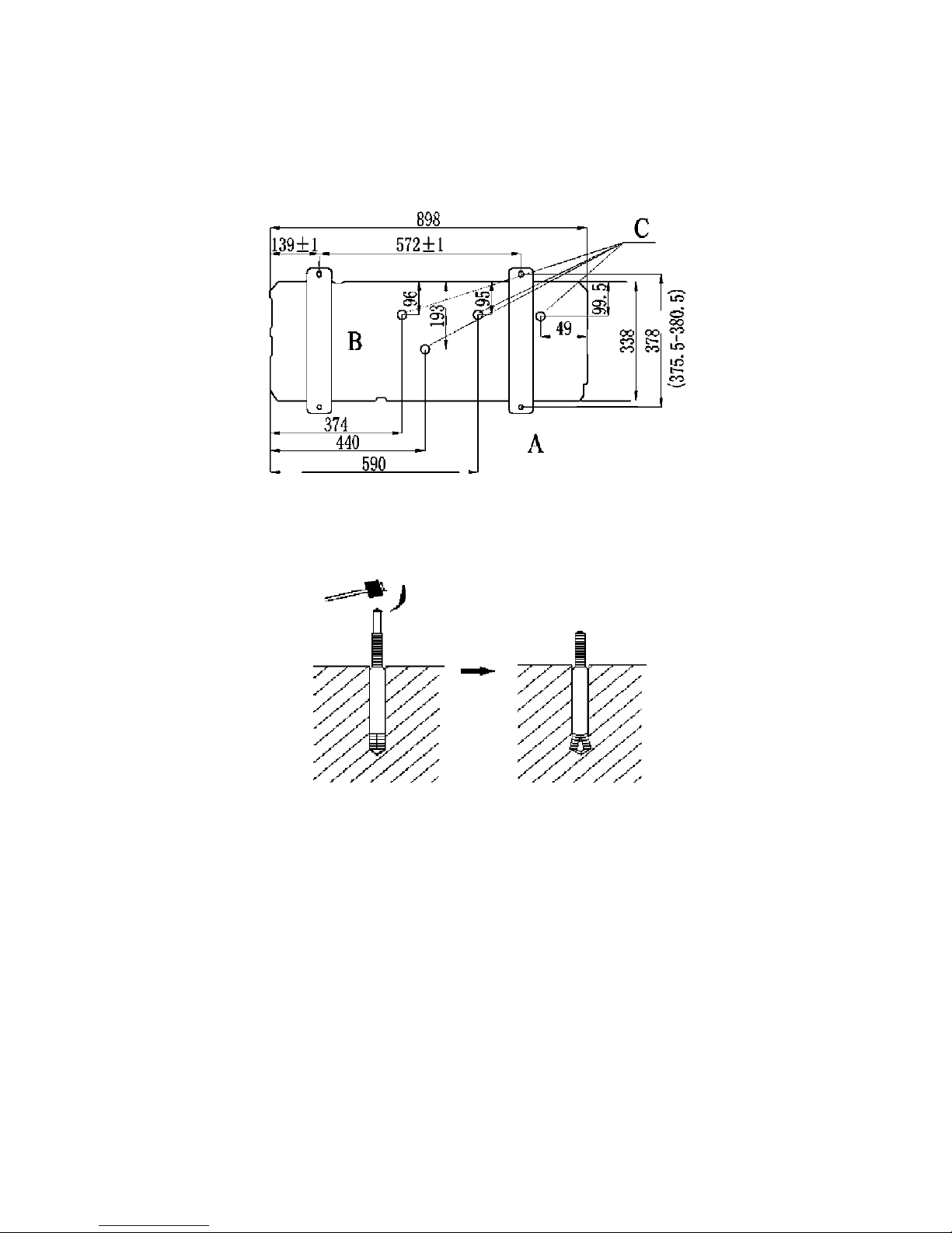
5 Installation Instruction
1) Check the installation location and ensure it is strength and level, so that the unit will not
cause any operating vibration or noise after installation.
2) In accordance with the foundation drawing in the Fig. 6, please drill 4 holes in the installation
location.
A: The outlet side B: Bottom view (mm) C: Drain hole
Fig. 6
3) Fix the unit securely with the foundation bolts. You can get the M10 or M8 foundation bolts,
nuts and washers from the market.
Fig. 7
4)
Rubber or spring shock absorbers should be used during the installation of the outdoor
unit to meet the noise and vibration requirements.
5)
Screw the foundation bolts into the ground, and it is better that their length is less than
20mm from the foundation face.
11
6 Installation of Refrigerant Pipes
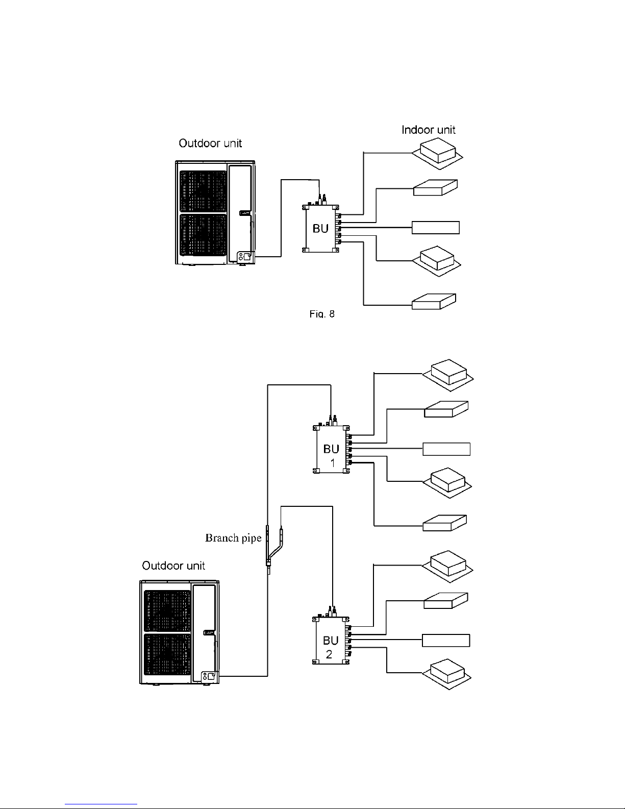
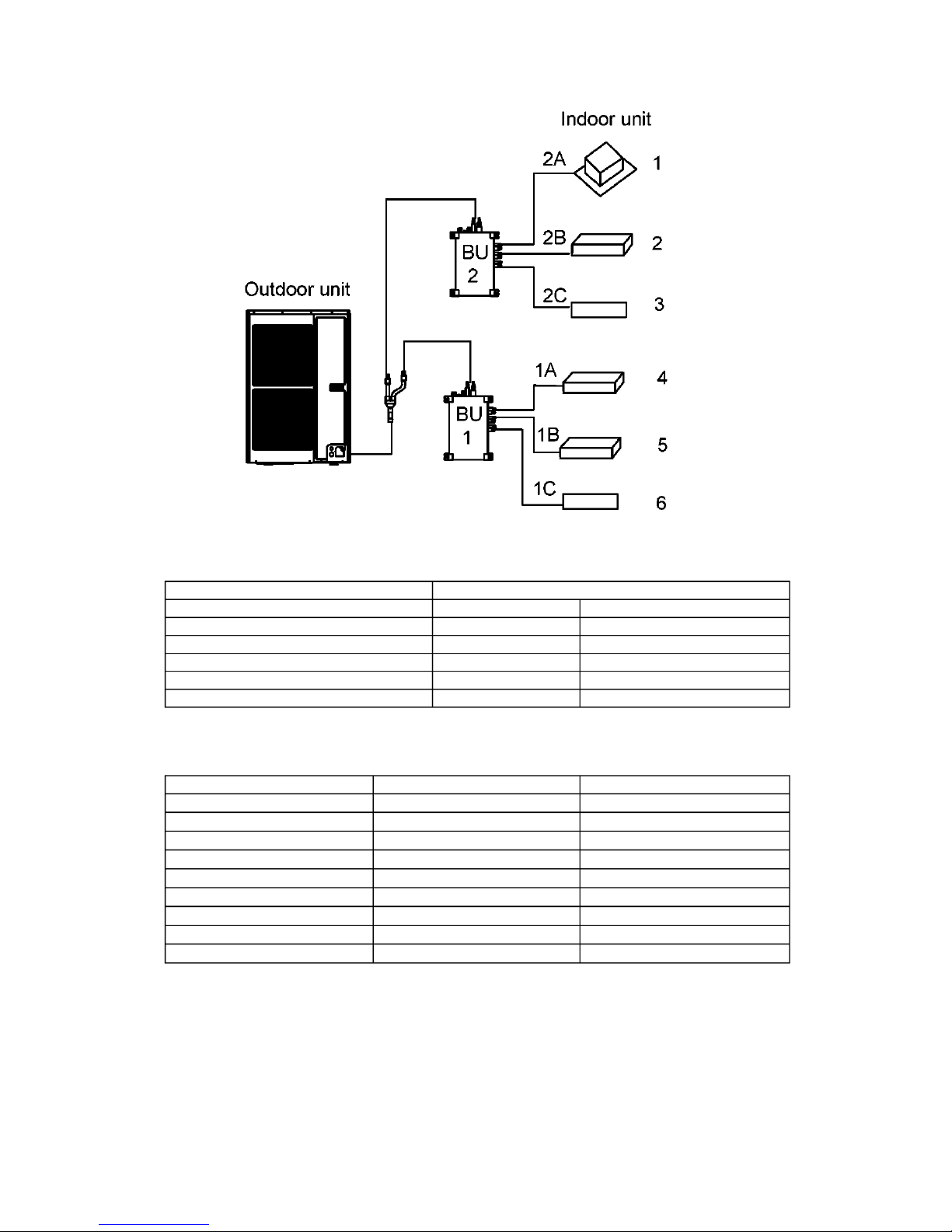
6.1 Manifold Mode of Connecting Pipe
1) For only one BU module, there will not be more than three indoor units.
2) For two BU modules, there will not be more than nine indoor units.
Indoor unit
Fig. 9
12
3) For three BU modules, there will not be more than nine indoor units.
Fig. 10
13
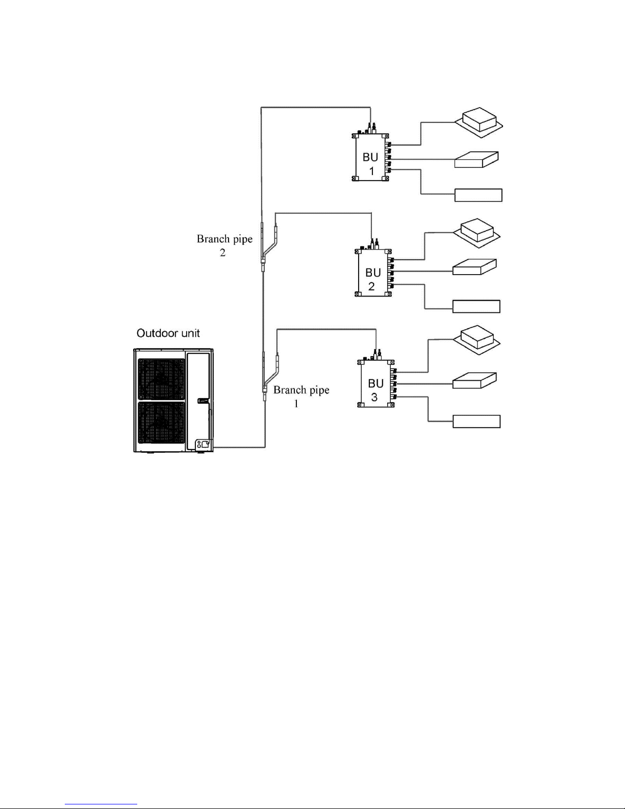
The sorts
The pipes
Length
(m)
Maximum
allowable
length
Between outdoor unit and BU
L1+L2+L3+L4+L5
≤55
Between
indoor unit
and BU
ACP-48COFM140GEEI
1A+1B+1C+2A+2B+2C+
3A+3B+3C
≤80
ACP-56COFM164GEEI
≤90
Between indoor unit and BU
module
1A;1B;1C;2A;2B;2C;3A;3B;3C
≤15
Between indoor unit and the 1st
branch
L4+1B;L2+L5+2A;
L2+L3+3B
≤40
Maximum
allowable
length
Between outdoor and indoor units
H1
≤30
Between outdoor units and BU
H2
≤30
Between BU and BU modules
H3
≤15
Between indoor and indoor units
H4
≤15
Minimum
allowable
length
Between outdoor and
the 1st branch
L1
≥5
Between BU and the branch
L3;L4;L5
as possible
as short
6.2 Allowable Length and Drop Height of Connecting Pipe
Fig. 11 (9 in door units)
Table 3
14
6.3 Dimension of Connecting Pipe
Table 4
Sorts
Gas Pipe
(mm)
Liquid Pipe
(mm)
Capacity of indoor
unit(Btu/h)
7000,9000,12000
Φ9.52
Φ6.35
18000
Φ12.7
Φ6.35
21000,24000
Φ15.9
Φ9.52
Outdoor unit
ACP-48COFM140GEEI
Φ15.9
Φ9.52
ACP-56COFM164GEEI
Φ15.9
Φ9.52
Between outdoor unit
and the 1st branch
The pipe L1
Φ19.05
Φ9.52
Between the 1st and the
2nd branch
The pipe L2
Φ15.9
Φ9.52
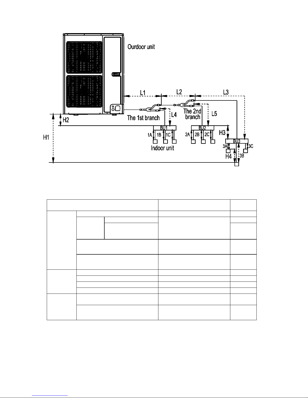
6.4 Connection of Branch Pipe
1) If two or three BU modules used, Y-type branch pipe of FQ01A/A will be chosen.
FQ01A/A (Liquid pipe) FQ01A/A (Gas pipe)
Fig. 12
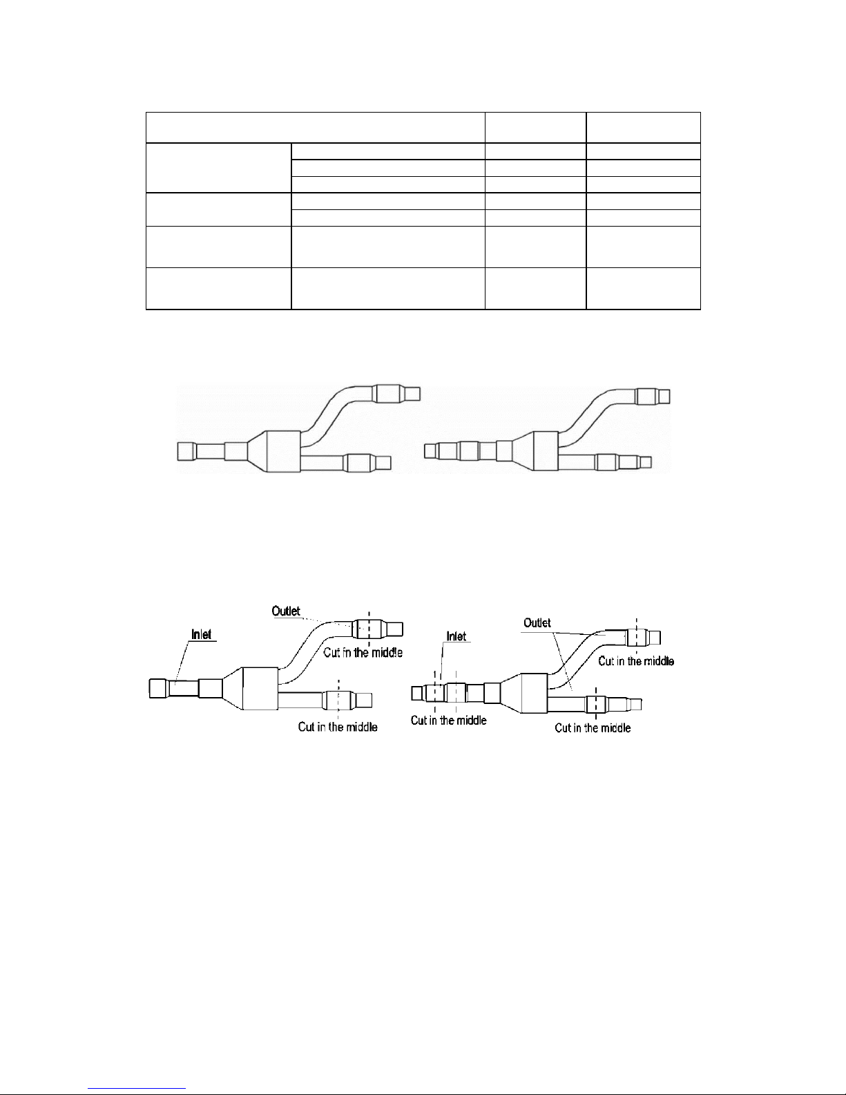
2) Y-type branch pipe is equipped with auxiliary tubes to adjust the diameter of different pipes. If
the dimension of the pipe selected is different from the dimension of branch pipe joint, Cut the
copper tube in the middle with tube cutter and clear up burrs. Please do that as following
figure.
Fig. 13
3) Y-type branch pipe must be installed in vertical or horizontal direction. In the inlet of the
branch pipe, keep at least 500mm straight pipe.
15
6.5 Precaution for Connection
1) Pipe connections should be follow the following rules:
① Outdoor unit shall be installed close to the indoor unit, hence to minimize the length and
bends of connection pipes.
② The gap of outdoor unit and indoor units should be as small as possible
③ The bending diameter of the pipeline is better as large as possible.
2) The brazing operation must be strictly in accordance with the process requirements. During the
installation, do not damage the pipeline and the bending diameter must be greater than
200mm.
3) The connection pipe cannot often be bent or straightened. Otherwise it will harden.
4) The elbow operation must use the elbow. Otherwise, the pipe may be cracking.
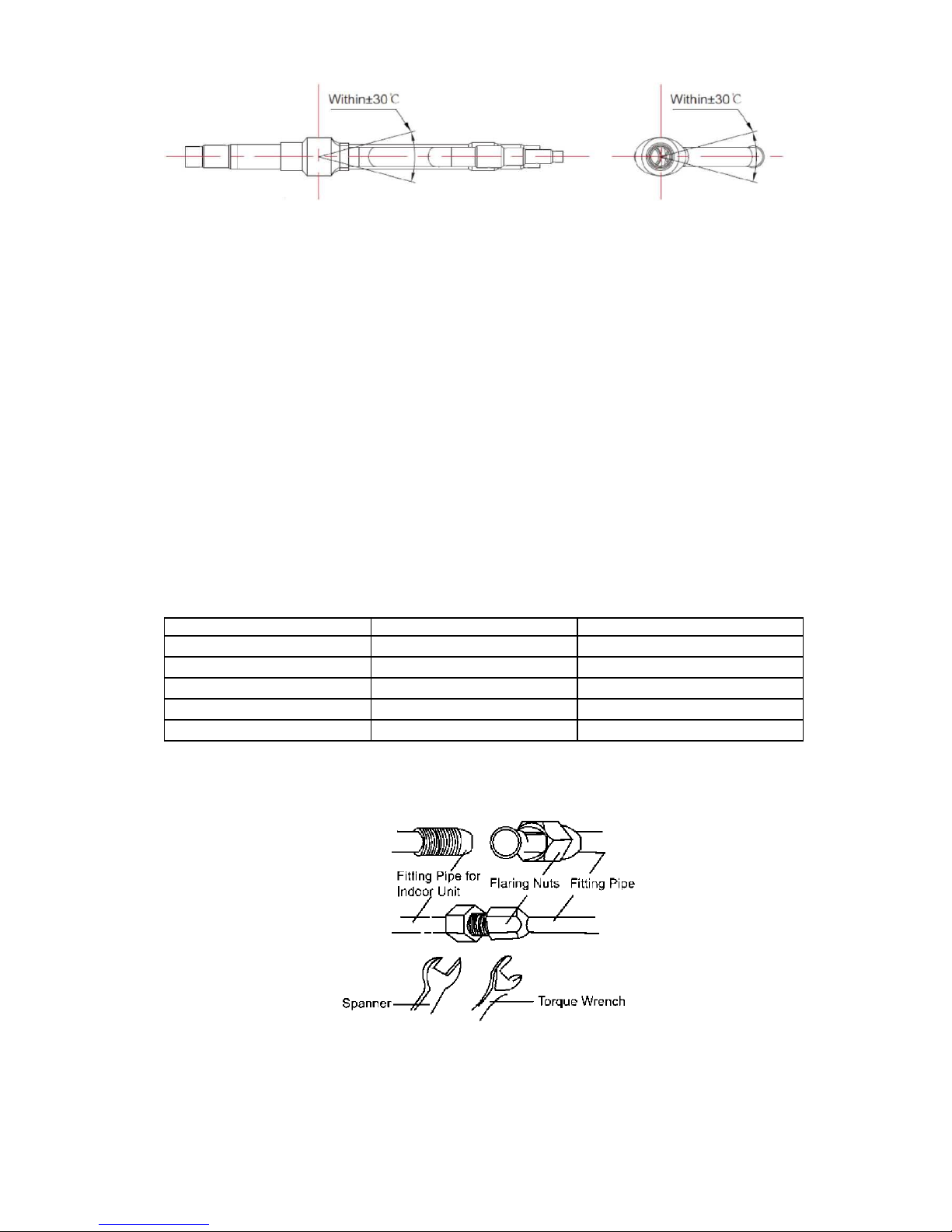
5) The process of flaring
① Using the tube cutter cutting the connecting pipe in the middle and remove the burrs.
② Install the nut before the flaring operation.
③ Check the flared portion, whether there is fractured or not.
6) The following table for the torque required to tighten the nuts.
Table 5
Pipe diameter (mm)
Wall thickness (mm)
Tightening torque (N-m)
Φ6.35
≥0.5
15~30
Φ9.52
≥0.71
30~40
Φ12.7
≥1
45~50
Φ15.9
≥1
60~65
Φ19.05
≥1
70~75
7) Align the flared end of copper tube with the center of pipe joint. Tighten the nuts with hands.
8) Tighten the flaring nuts with torque wrench until you hear a "click".
Fig. 14
Fig. 15
16
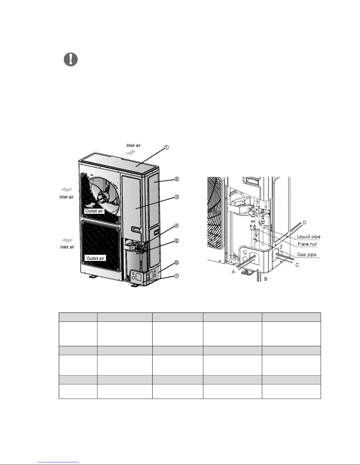
6.6 Connection of Refrigerant Pipe
9) After all the refrigerant installation has been done, use nitrogen to carry out gas leak check.
♦
♦
♦
Caution!
During the connection of the indoor unit or BU module to the refrigerant pipe, never pull any
joints of the indoor unit or the BU module by force; otherwise the capillary pipe or other pipe
may crack, which then would result in leakage.
The refrigerant pipe should be supported by brackets, that is, don't let the unit withstand the
weight of it.
For the Super Free Match system, each pipe should be labeled to tell which system it
belongs to avoid mistaken inaccurate piping.
NO.
① ② ③
④
Name Coping plate Rear side plate
Front side plate
Gas side stop
valve
NO.
⑤ ⑥ ⑦
Name
Liquid side stop
valve
Right connection
board
Front
connection
board
NO.
A B C
D
Name
Front connection
Bottom
connection
Side connection
Rear connection
Fig. 16
17
1) Unscrew the coping plate, front side plate, right connection board and front connection board.
2) The refrigerant pipes can be installed in four directions, please choose the proper direction.
3) Knock the holes in the plate of the chosen direction with the drill and hammer.
4) Connect the pipes to the stop valves.
5) Bend the pipes to go through the knockout holes.
6) Cover the through-holes with sealing materials to prevent the water, dust or small animals
going into the outdoor unit.
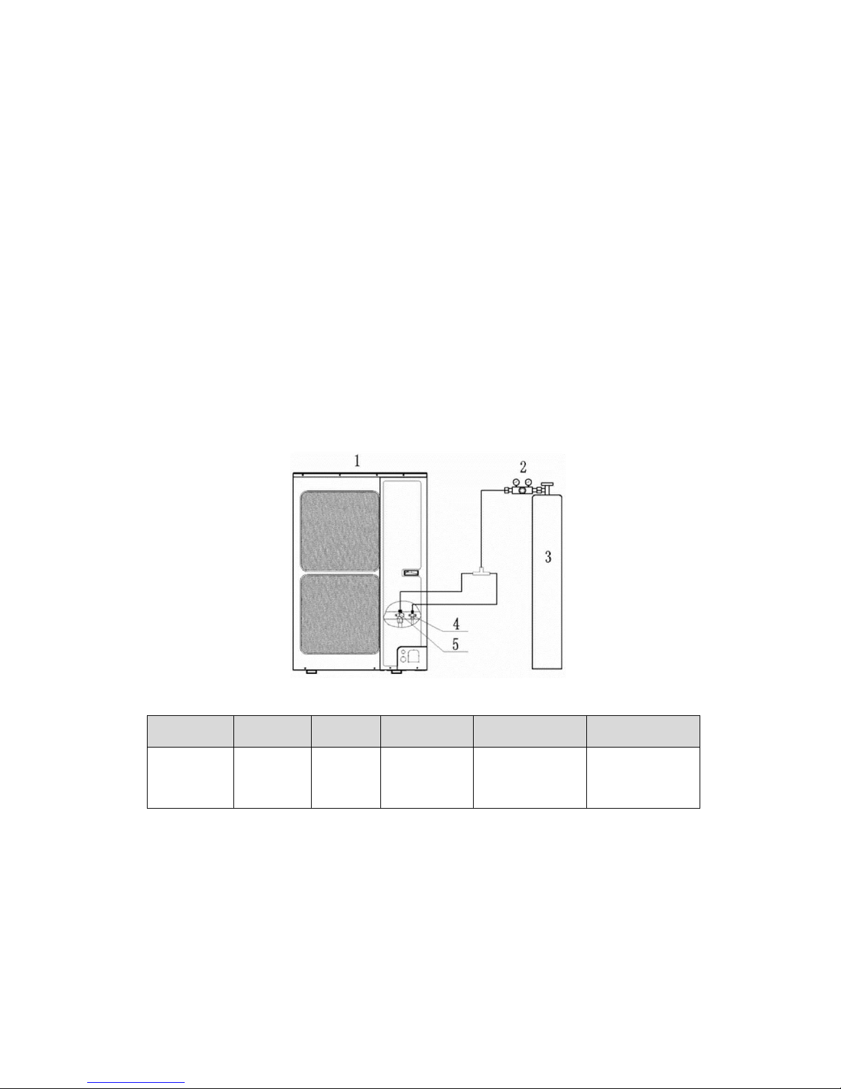
6.7 Leak Test
1) Please make sure that the stop valves of the outdoor unit are closed during the operation.
2) The leak test should be made by pressurizing nitrogen gas.
3) Open the pressure reducing valve, pressurize the connection pipes to 1.0 MPa (10 bar)
slowly, wait ten minutes, and make sure that the pressure will not drop.
4) Rise the pressure to 4.0 MPa (40 bar) slowly, wait 24 hours, and make sure the pressure will
not drop.
5) If the pressure does not decrease, the pipes have passed the test. Otherwise, look for where
the gas leaks from.
Fig. 17
NO.
1
2 3 4
5
Name
Outdoor
unit
Pressure
reducing
valve
Nitrogen
Liquid side stop
valve
Gas side stop
valve
18
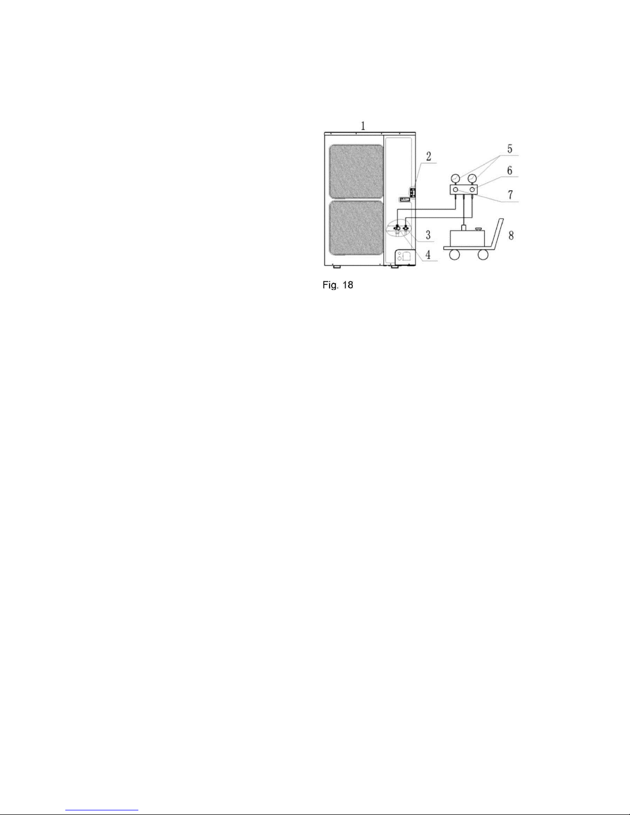
6.8 Vacuum Operation
1) Make sure that the liquid and gas stop valve of the outdoor unit are closed fully during the
operation.
2) As shown in the following figure, expel the gas from the refrigerant pipes by the vacuum
pump.
1: Outdoor unit
2: Service port
3: Liquid side stop valve
4: Gas side stop valve
5: Pressure-vacuum gauge
6: Hi-knob
7: Lo-knob
8: Vacuum pump
3) Open the pump and turn on the knobs to
evacuate the gas in the liquid and gas pipes.
4) When the pressure of the system is less than -0.1Mpa (-1bar), keep the system for more than
one hour under the condition.
5) Then turn off the knobs and the pump, and if the pressure of the pressure-vacuum gauge
does not rise within 2 hours, the system is under a vacuum. Otherwise, the system has
leaked, please look for where the gas leaks in.
6.9 Refrigerant Charging
6.9.1 The refrigerant has been charged into the outdoor unit before shipped from the
manufacturer, while additional refrigerant still need be charged into the refrigerant pipe
during the field installation.
6.9.2 Calculation of the Additional Refrigerant Charging
1) Get the refrigerant charge of the outdoor unit from the nameplate.
Note:
♦ The refrigerant charge of the outdoor unit does not include the charged additionally in the
indoor unit, BU module and the refrigerant pipe.
♦ For the length of the connecting pipe is decided on the field, the amount of additional
refrigerant shall be decided depending on the dimension and the length of the liquid pipe
used on the field.
♦ Record the additional refrigerant charge for future maintenance.
♦ It does not need to add refrigerant if the total length of liquid pipe is within 30m.
2) Calculating the Mass of Additional Refrigerant
Additional Refrigerant Charge (kg) = Σ the Liquid Pipe Length of Φ6.35x0.022kg/m +Σ the
Liquid Pipe Length of Φ9.52x0.054kg/m-1.47(kg)
♦ If the additional refrigerant charge is negative, it does not need to add the refrigerant.
19
3) Example: ACP-56COFM164GEEI
Serial No.
Model
Indoor unit 1
Cassette type
ACP-12CCIFM35GEEI
Indoor unit 2
Duct type
ACP-09DTIFM25GEEI
Indoor unit 3
Wall mounted type
ACP-09CIFM25GEEI
Indoor unit 4
Duct type
ACP-09DTIFM25GEEI
Indoor unit 5
Duct type
ACP-09DTIFM25GEEI
Indoor unit 6
Wall mounted type
ACP-09CIFM25GEEI
Table 7
Serial No.
Diameter(mm)
Length(m)
L1
Φ9.52
20
L2
Φ9.52
10
L4
Φ9.52
10
1A
Φ6.35
5
1B
Φ6.35
5
1C
Φ6.35
5
2A
Φ6.35
5
2B
Φ6.35
5
2C
Φ6.35
5
Fig. 19
Table 6
The total length of the liquid pipes: 20+10+10+5+5+5+5+5+5=70(m). Thus, the total
length is over than 30m, so the air conditioner needs to add refrigerant.
♦ Additional refrigerant charge
20
Σ the Liquid Pipe Length of Φ6.35x0.022kg/m + Σ the Liquid Pipe Length of
Φ 9.52xO.O54kg/m
-1.47(kg)
=(5+5+5+5+5+5)(m)x0.022kg/m+(20+10+10)(m)x0.054kg/m-1.47(kg)
=1.35(kg)
4) Additional refrigerant charge record
Table 8
Diameter(mm)
Total length(m)
Additional refrigerant charge(kg)
Φ 6.35
Φ 9.52
Total
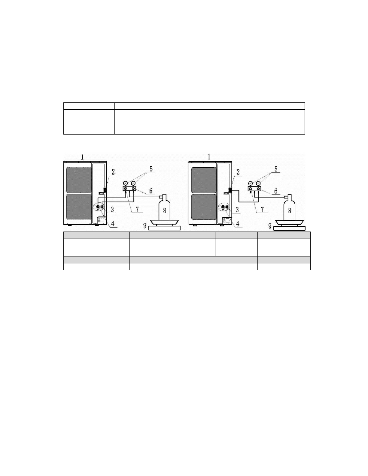
6.9.3 Procedures for adding refrigerant
NO. 1 2 3 4
5
Name
Outdoor unit
Service port
Liquid side
stop valve
Gas side stop
valve
Pressure-vacuum
gauge
NO. 6 7 8 9
Name
Hi-knob
Lo-knob
R410A tank
Scale
Fig. 20
1) When the liquid and gas stop valves have not been opened, the system is under the
vacuum:
① Refer to the left of the Fig. 20, connect the R410A tank to the system.
② Turn on the R410A tank and the Hi-knob, charge the R410A refrigerant into the system
from the liquid side stop valve. The Lo-knob should be closed completely.
③ Turn off the R410A tank and the Hi-knob immediately, when the adding refrigerant is
enough.
④ Turn on the liquid and gas side stop valves in an anticlockwise direction slowly and completely.
2) If the pressure of the system is too high to charge refrigerant, you can do as follow.
① Turn on the liquid and gas side stop valves in an anticlockwise direction slowly and completely.
② Turn on the power of the air conditioner, and set cooling mode, running more than 0.5h when
outside temperature is higher than 15°C DB.
a) Refer to the left of the Fig. 20, connect the R410A tank to the system.
21
b) Turn on the R410A tank and the Lo-knob, charge the R410A refrigerant into the system
from the gas side stop valve. The Hi-knob should be closed completely.
c) Turn off the R410A tank and the Lo-knob immediately, when adding refrigerant is
enough.
③ Turn on the power of the air conditioner, and set heating mode, running more than 0.5h when
outside temperature is lower than 15°C DB.
a) Refer to the right of the Fig. 20, connect the R410A tank to the system.
b) Turn on the R410A tank and the Hi-knob, charge the R410A refrigerant into the system
from service port. The Lo-knob should be closed completely.
c) Turn off the R410A tank and the Hi-knob immediately, when adding refrigerant is
enough.
Caution!
♦ Make sure the liquid and gas side stop valves are opened completely after the installation.
♦ Make sure exact refrigerant charge for the liquid pipe
♦ Additional refrigerant charge must be measured exactly.
♦ Make sure charging the liquid refrigerant into the system.
♦ Please prevent the refrigerant leakage from your body when removing charging hose.
♦ Please heat the refrigerant tank with hot water or hot air when the outside temperature is too
low. However, it must be forbidden to heat with fire directly, otherwise it may lead to
explosion.
22
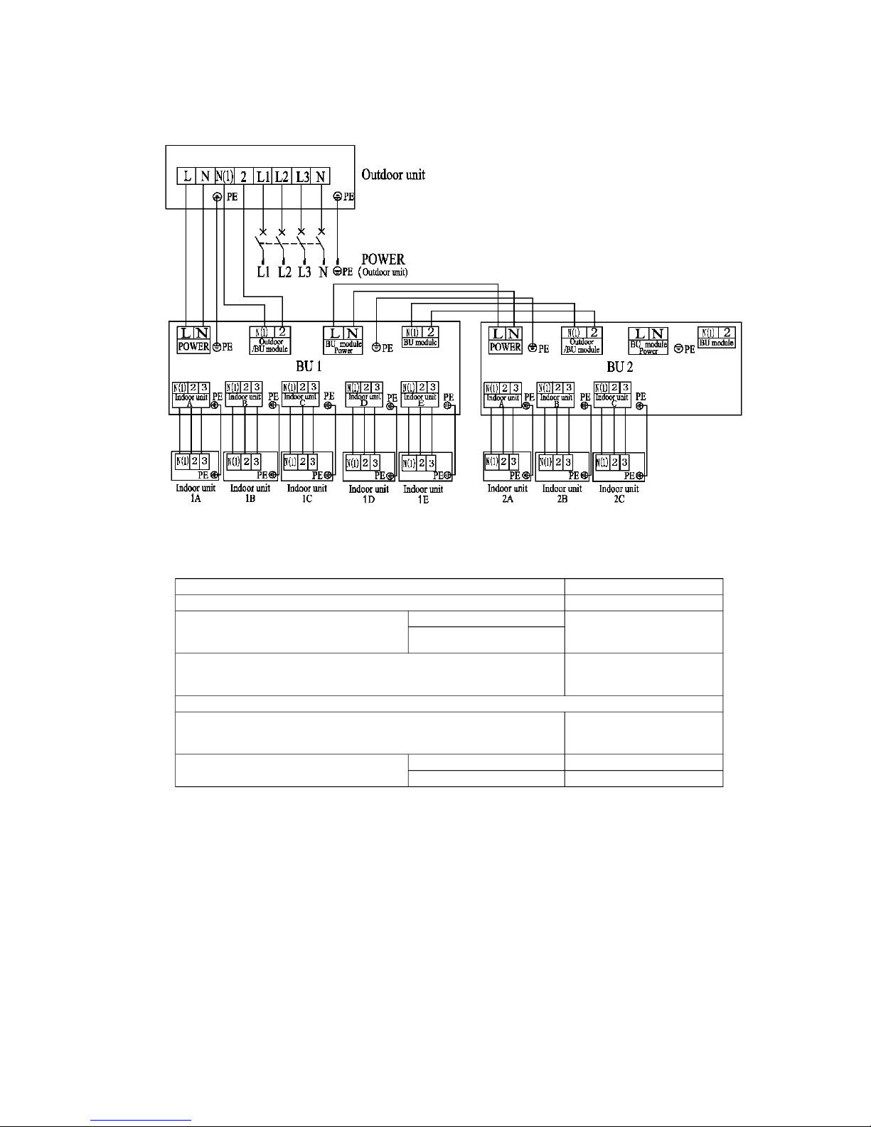
Note:
♦ The total length of the transmission line between the outdoor unit and the furthest BU
module is not more than 55m. Otherwise, the system cannot work possibility.
♦ The specifications of the power cable and transmission line listed in the table above are
determined based on the maximum power (maximum amps) of the unit.
♦ The specifications of the power cable listed in the table above are applied to the
7 Electrical Wiring Work 7.1
Wiring Connection
Phase and frequency
3Ph,50Hz
Voltage
380~415V
Recommended cable of outdoor unit
(Pieces x Sectional area)
ACP-48COFM140GEEI
5x2.5 mm
2
ACP-56COFM164GEEI
Recommended cable of BU module
(Pieces x Sectional area)
3x0.75 mm
2
Transmission line (Pieces x Sectional area) 2x1.0 mm
2
Recommended cable of indoor unit
(Pieces x Sectional area)
4x0.75mm
2
Capacity of the air switch
ACP-48COFM140GEEI
25A
ACP-56COFM164GEEI
25A
Fig. 21
7.2 Requirements of Power Circuit and Cable
Table 9

23
conduit-guarded multi-wire copper cable (like, YJV copper cable, consisting of PE insulated
wires and a PVC cable jacket) used at 40°C and resistible to 90°C. If the working condition
changes, they should be modified according to the related national standard.
♦ The specifications of the air switch listed in the table above are applied to the breaker with
the working temperature at 40C. If the working condition changes, they should be modified
according to the related national standard.
♦ The length of the recommended power cable should be less than 15 meters; otherwise, the
diameter of the power cable is not enough.
♦ Mentioned power cable and transmission line length is just a reference value. It may be
different depending on the condition of installation, humidity or materials, etc.
7.3 Ground Requirements
♦ The air conditioner is classified into the Class I appliances, so its ground ways must be
reliable.
♦ The ground wire must be fixed on the screw hole with the sign as the right
figure.
♦ The yellow-green wire of the air conditioner is the ground wire and must be fixed by the
tapping screw. And it cannot be used for other purpose or cut off. Otherwise, it will cause the
hazard of electric shock.
♦ The reliable ground terminal should be provided and the ground wire cannot be connected to
any of the following places: a. Water pipe; b. Coal gas pipe; c. Sewage pipe; d. Lightning rod
e. Telephone line f. Other unreliable places considered by a professional.
7.4 Precautions on the Electrical Wiring Work
♦ The ground connection should be reliable and the ground wire should be connected to the
dedicated device of the building by the professional.
♦ The electric installation should be carried out by the professional as instructed by the local
laws, regulations and also this manual.
♦ The air switch coupled with the leakage current protection switch must be equipped in the
circuits, which is of enough capacity and of both magnetic and thermal tripping functions in
case of the short circuit and overload.
♦ The power supply of the outdoor unit and all the BU modules should be separately.
♦ The electrical work should use a cable length enough to cover the entire distance with no
connection. If it is unavoidable, please make sure the connection should be reliable and the
external forces will not act on the wires. Otherwise it will cause electrical shock or fire etc.
♦ The power cable with the rated voltage and exclusive circuit for the air conditioning should be
used.
♦ Do not pull the power cable by force.
♦ The diameter of the power cable should be large enough and once it is damaged, it must be
replaced by the dedicated one.

24
7.5 Precaution of Laying Wires
1) Use a wire stripper to strip off about 25mm of the insulation layer at the end of the wires;
2) Loosen the screws on the terminal block of the air conditioner;
3) Use the pliers to bend the end of the wire into a ring shape corresponding the size of the
screw;
4) Pass the screw through the wire ring and fix it onto the terminal block.
Fig. 22
7.6 Procedures for Electrical Wiring Work
1) Knock the holes in the plate of the chosen direction with the hammer.
2) Place the rubber ring on the knockout hole.
3) Let the power cable and transmission line go through the knockout hole.
4) Connect the power cable of the outdoor unit to the L1, L2 terminals with the sign of the XT1
and as well as the ground screw.
5) Connect the transmission line of the outdoor unit to the N(1), 2 terminals with the sign of
the XT2.
6) Fix the power cable and transmission line firmly by cable fixing clip.
7) Screw the coping plate, front side plate, right connection board, front connection board back.
8) Cover the through-holes with sealing materials to prevent the water, dust or small animals
going into the outdoor unit.
Caution!
♦ The transmission line and the power cable must be separated and separated with an interval
of at least 2cm; otherwise it may be result in communication problem.
♦ In order to protect the power cable and transmission line from damaging by the hole, the
rubber ring must be placed on the hole. Otherwise, it may cause electrical shock or fire etc.
♦ The power wire and transmission line must be more than one meter away from televisions or
radios which can emit electromagnetic waves to prevent image interference or noise.
Otherwise, the unit maybe cannot work.
♦ Confirm the each cable connected to the terminal screw is exactly and securely after finishing
the electric work.
♦ Fix each ground wire separately with the ground screw.
♦ If the connecting wire is connected to the terminal incorrectly, the unit will not work normally.
25
8 Design of Drainage Pipeline
8.1 Installation of Drain Hose
1) Choose one drain hole in the bottom of the outdoor unit.
2) Connect the drain hose to the drain hole.
3) The drain hose should be kept at 5~10 degrees of gradient to facilitate discharge of the
condensing water. Take care that does not exert too much force on the hose.
4) Thermal insulation materials should be placed at the joints of the drain hose so as to prevent
from dew condensation. Fix the drain hose firmly by binding band.
Fig. 23
5) The end of the drain hose should be inserted into the hole of drainage pipeline.
8.2 Design of Drainage Pipeline
1) The drainage pipeline should be kept at a certain gradient (1/50—1/100) so as to avoid
bulges of pipes where there might be water bends.
2) The drainage pipeline is form of the hard PVC pipes for common purposes which can be
purchased locally. The diameter of the PVC pipes is not less than 31mm and the pipeline
should be fixed as close to the BU module as possible.
3) Insert the drain hose into the drain hole of drainage pipeline. Use binding band to fix it tightly.
It is not allowed to use adhesive glue to join the drain hose to the drainage hole.
4) When the drainage pipeline is laid for a couple of units, the position of the shared pipeline
should be approximately 100mm lower than the drainage hole of each module. In this case,
some special-purpose pipes with thicker walls will be used.
5) At intervals of about 1 meter, fix the drain pipes to the wall with brackets, not floating in the
air.
 Loading...