

Vivax ACP-12CT35GECI, ACP-18CT50GECI Service Manual

ACP-12CT35GECI
ACP-18CT50GECI
Service
manual
ENG
RoHS
NNO-1/09


Summary and Features...............................................................................
Part 1 Safety Precautions
.......................................................................................
Part 2 Specifications
..................................................................................................
2.1 Unit Specifications...............................................................................................
2.3 Capacity Variation Ratio According toTemperature............................................
2.4 Operation Data....................................................................................................
Part 3 Construction Views
.....................................................................................
3.1 Indoor Unit ..........................................................................................................
3.2 Outdoor Unit .......................................................................................................
Part 4 Refrigerant System Diagram
..................................................................
5.1 Electrical Data......................................................................................................
5.2 Electrical Wiring....................................................................................................
Part 5 Schematic Diagram
......................................................................................
6.1 Remote Control Operations.................................................................................
6.2 Description of Each Control Operation................................................................
Part 6 Function and Control
..................................................................................
Part 7 Installation Manual
.......................................................................................
Table of Contents
5.3 Printed Circuit Board............................................................................................
7.1
Choosing an Installation Site
..............................................................................
7.2
Indoor Unit Installation Drawings
........................................................................
7.3 Installation Tips .................................................................................................
7.4 Indoor unit Installation.........................................................................................
2.2 Operation Characteristic Curve............................................................................
2.5 Noise Criteria Curve Tables for Both Models......................................................
1
2
3
3
7
7
8
9
11
12
13
13
13
15
18
18
22
24
24
24
26
27
10
10

Part 8 Exploded Views and Parts List
..............................................................34
Part 9 Troubleshooting
...............................................................................................40
9.1
Precautions Before Performing Inspection or Repair
...........................................40
9.2
Confirmation
.........................................................................................................40
9.3
Flashing LED of Indoor/Outdoor Unit and Primary Judgement
...........................40
9.4
How to Check Simply the Main Part
.....................................................................43
8.1 Indoor Unit............................................................................................................34
8.2 Outdoor Unit.........................................................................................................36
Part10 Removal Procedure
.......................................................................................48
10.1
Removal Procedure of Indoor Unit
.....................................................................48
10.2
Removal Procedure of Outdoor Unit(09K/12K)
..................................................53
10.3
Removal Procedure of Outdoor Unit(18K)
.........................................................57
Table of Contents
Summary and features
1
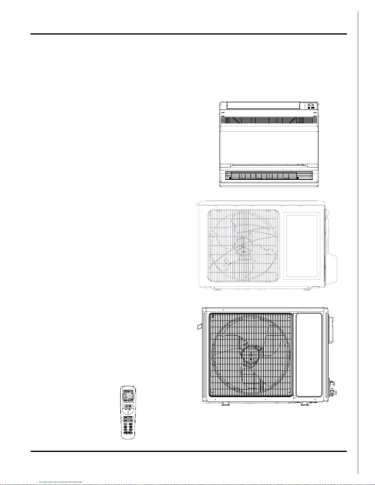
Summary and Features
Indoor Unit
ACP-12CT35GECI
ACP-18CT50GECI
Outdoor Unit
ACP-12CT35GECI
Remote control
ACP-18CT50GECI
2
Safety Precautions
Installing, starting up, and servicing air conditioner can be
hazardous due to system pressure, electrical components,
and equipment location, etc.
Only trained, qualified installers and service personnel are
allowed to install, start-up, and service this equipment.
Untrained personnel can perform basic maintenance functions such as cleaning coils. All other operations should
be performed by trained service personnel.
When handling the equipment, observe precautions in the
manual and on tags, stickers, and labels attached to the
equipment. Follow all safety codes. Wear safety glasses
andwork gloves. Keep quenching cloth and fire extinguisher
nearby when brazing.
Read the instructions thoroughly and follow all warnings or
cautions in literature and attached to the unit. Consult local
building codes and current editions of national as well as
local electrical codes.
Recognize the following safety information:
Incorrect handling could result in
personal injury or death.
Incorrect handling may result in
minor injury,or damage to product
or property.
Warning
Caution
Caution
Warning
All electric work must be performed by a licensed technician
according to local regulations and the instructions given in
this manual.
Before installing, modifying, or servicing system, main
electrical disconnect switch must be in the OFF position.
There may be more than 1 disconnect switch. Lock out
and tag switch with a suitable warning label.
Never supply power to the unit unless all wiring and tubing are completed, reconnected and checked.
This system adopts highly dangerous electrical voltage.
Incorrect connection or inadequate grounding can cause
personal injury or death. Stick to the wiring diagram and
all the instructions when wiring.
Have the unit adequately grounded in accordance with
local electrical codes.
All installation or repair work shall be performed by your dealer or a specialized subcontractor as there is the risk of fire,
electric shock, explosion or injury.
Have all wiring connected tightly. Loose connection may
lead to overheating and a possible fire hazard.
Make sure the outdoor unit is installed on a stable, level
surface with no accumulation of snow, leaves, or trash
beside.
Make sure the ceiling/wall is strong enough to bear the
weight of the unit.
Make sure the noise of the outdoor unit does not disturb
neighbors.
Follow all the installation instructions to minimize the risk
of damage from earthquakes, typhoons or strong winds.
Avoid contact between refrigerant and fire as it generates
poisonous gas.
Apply specified refrigerant only. Never have it mixed with
any other refrigerant. Never have air remain in the
refrigerant line as it may lead to rupture and other hazards.
Make sure no refrigerant gas is leaking out when installation is completed.
Should there be refrigerant leakage, the density of refrigerant in the air shall in no way exceed its limited value,
or it may lead to explosion.
Keep your fingers and clothing away from any moving
parts.
Clear the site after installation. Make sure no foreign objects are left in the unit.
Always ensure effective grounding for the unit.
Never install the unit in a place where a combustible gas
might leak, or it may lead to fire or explosion.
Properly insulate any tubing running inside the room to
prevent the water from damaging the wall.
1.Safety Precautions
Make a proper provision against noise when the unit is
installed at a telecommunication center or hospital.
Provide an electric leak breaker when it is installed in a
watery place.
Never wash the unit with water.
Should any emergency occur, stop the unit and disconnect the power immediately.
Handle unit transportation with care. The unit should not
be carried by only one person if it is more than 20kg.
Never touch the heat exchanger fins with bare hands.
Never touch the compressor or refrigerant piping without
wearing glove.
Do not have the unit operate without air filter.
3
Specifications
2.Specifications
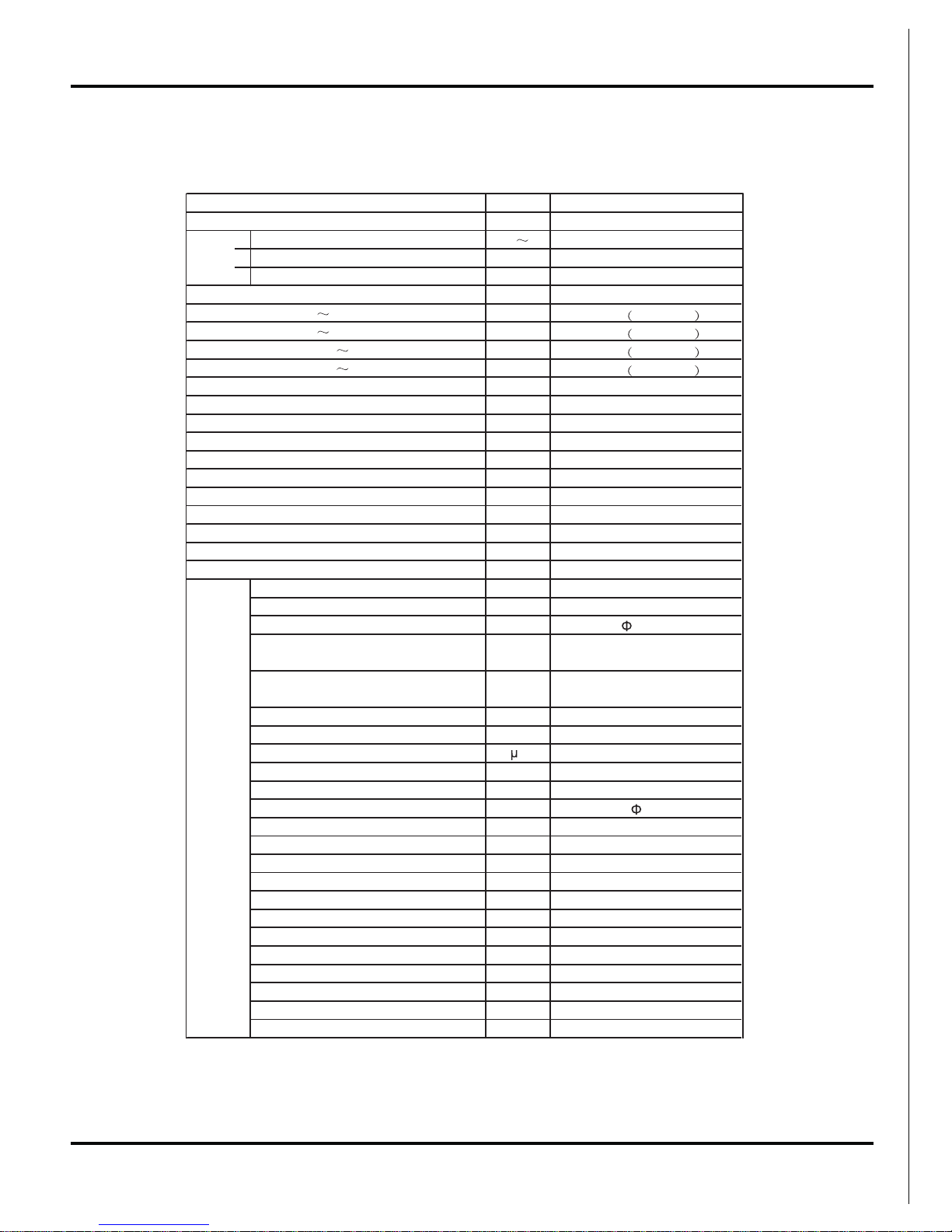
2.1 Unit Specifications
ACP-18CT50GECI
CV01000020
Rated Voltage V
220-240
Rated Frequency Hz
50
Phases
1
Indoor
W
3520
600~3950
W
4000
600~4700
W
1080
220~1700
W
1108
220~1500
A
4.70
A
4.82
W
1700
A
7.39
m
3
/h
600/520/-/440/-/360/280
2.1
h/L
62.3
W/W
16.3
W/W
-
W/W
-
W/W
m
2
16-24
Model of indoor unit
ACP-18CT50GECI
Fan Type
Centrifugal
Diameter Length(DXL) mm
370X80
Fan Motor Cooling Speed
(SH/H/HM/M//LM/L/S)
r/min 750/650/600/550/500/450/350
Fan Motor Heating Speed
(SH/H/HM/M//LM/L/S)
r/min 750/650/600/550/500/450/350
Output of Fan Motor W
20
Fan Motor RLA A
0.34
Fan Motor Capacitor
F
-
Input of Heater W
-
Evaporator Form Aluminum Fin-copper Tube
Pipe Diameter mm
6.35
Row-fin Gap mm
2-1.2
Coil Length (LXDXW) mm
511X24X396
Swi n g Mot o r Mod el
MP24AE
Output of Swing Motor W
2.0
Fus e A
PCB 3.15A
Sound Pressure Level (SH/H/M/L/SL) dB (A) 42/40/38/37/35/32/26
Sound Power Level (SH/H/M/L/SL) dB (A) 52/50/48/47/45/42/36
Dimension (WXHXD) mm
700X600X215
Dimension of Carton Box (L/W/H) mm
785X680X280
Dimension of Package (L/W/H) mm
788X695X283
Net Weight kg
15
Gross Weight kg
18
Mo d e l
Product Code
Power
Supply
Power Supply Mode
Cooling Capacity (Min
Ma x)
Heating Capacity (Min
Ma x)
Cooling Power Input (Min
Ma x)
Heating Power Input (Min
Ma x)
Cooling Power Current
Heating Power Current
Rated Input
Rated Current
Air Flow Volume(SH/H/M/L/SL)
Dehumidifying Volume
EER
COP
SEER
HSPF
Application Area
Indoor
Unit
4
Specifications
The above data is subject to change without notice. Please refer to the nameplate of the unit.
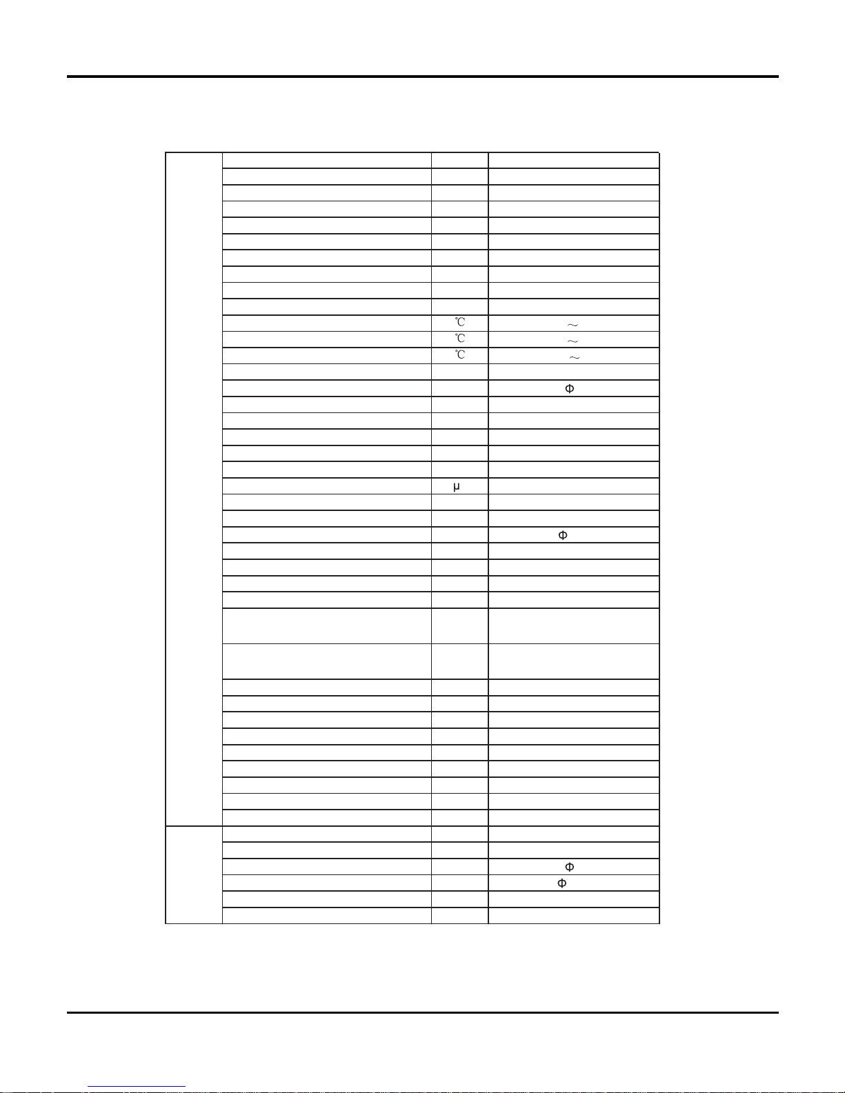
Model of Outdoor Unit
ACP-12CT35GECI
Compressor Manufacturer/Trademark
DIT/daikin
Compressor Model
1YC23AEXD
Compress or Oil
DAPHNE FVC50K
Compressor Type
Rotary
L.R.A. A
20
Compressor RLA A
4.00
Compressor Power Input W
600
Overload Protector
CS-7SA
Throttling Method
Capillary
Operation temp
16 30
Ambient temp (cooling)
10 48
Ambient temp (heating)
-15 24
Condenser Form
Pipe Diameter mm
7
Rows-fin Gap mm
2-1.4
Coil Length (LXWXD) mm
7 24 X5 08 X3 8. 1
Fan Motor Speed rpm
820
Output of Fan Motor W
30
Fan Motor RLA A
0.42
Fan Motor Capacitor
2
F
Ai r Fl ow Volum e o f Ou tdoor Uni t
m
3
/h
0061
wolf-laixA
epyT naF
mmretemaiD naF
400
gnitsorfeD citamotuA
dohteM gnitsorfeD
1T
epyT etamilC
I
noitalosI
42PI
noitcetorP erutsioM
Permissible Excessive Operating
Pressure for the Discharge Side
8.3
aPM
Permissible Excessive Operating
Pres sure for the Suction Si de
2.1
aPM
-/-/25
)A( Bd)L/M/H( leveL erusserP dnuoS
-/-/26
)A( Bd)L/M/H( leveL rewoP dnuoS
D
imension (WXHXD) mm 848X540X320
Dimension of Carton Box (L/W/H) mm 878X360X580
Dimension of Package (L/W/H) mm 881X363X595
33
gkthgieW teN
73
gkthgieW ssorG
A014R
tnaregirfeR
50.1
gkegrahC tnaregirfeR
5
mhtgneL
02
m/gegrahC lanoitiddA saG
O
uter Diameter Liquid Pipe mm
6
Outer Diameter Gas Pipe mm
9.52
01
mthgieH ecnatsiD xaM
51
mhtgneL ecnatsiD xaM
Outdoor
Unit
Connecti
on Pipe
5
Specifications
CV01000030
Rated Voltage V
220-240
Rated Frequency Hz 50
Phas es 1
Indoor
W 5270˄900~5600
˅
W 5500˄900~6600
˅
W 1630˄360~2500
˅
W 1520˄350~2500
˅
A7.09
A6.61
W 2500
A10.87
m
3
/h
650/620/-/500/-/410/320
L/h 2
W/W 3.23
W/W 3.62
W/W -
W/W -
m
2
23-34
Model of indoor unit
Fan Type Centrifugal
Diameter Length(DXL) mm ĭ370X80
Fan Motor Cooling Speed (SH/H/HM/M/LM/L/S) r/min 840/800/720/650/580/530/410
Fan Motor Heating Speed (SH/H/HM/M/LM/L/S) r/min 900/840/760/690/620/570/450
Output of Fan Motor W 20
Fan Motor RLA A 0.34
Fan Motor Capacitor ȝF-
Input of Heater W -
Evaporator Form Aluminum Fin-copper Tube
Pipe Diameter mm ĭ6.35
Row-fin Gap mm 2-1.2
Coil Length (LXDXW) mm 511X24X396
Swin g Mo tor Mo de l MP24AE
Output of Swing Motor W 2.0
Fuse A PCB 3.15A
Sound Pressure Level (SH/H/M/L/SL) dB (A) 48/46/44/41/37/35/32
Sound Power Level (SH/H/M/L/SL) dB (A) 58/56/54/51/47/45/42
Dimension (WXHXD) mm 700X600X215
Dimension of Carton Box (L/W/H) mm 785X680X280
Dimension of Package (L/W/H) mm 788X695X283
Net Weight kg 15
Gross Weight kg 18
Mo de l
Product Code
Power
Supply
Power Supply Mode
Cooling Capacity (MinMa x)
Heating Capacity (MinMa x)
Cooling Power Input (MinMa x)
Heating Power Input (MinMa x)
Cooling Power Current
Heating Power Current
Rated Input
Rated Current
Air Flow Volume(SH/H/M/L/SL)
Dehumidifying Volume
EER
COP
SEER
HSPF
Application Area
Indoor
Unit
6
Specifications
The above data is subject to change without notice. Please refer to the nameplate of the unit.
Model of Outdoor Unit
Compressor Manufacturer/Trademark
China Resources (Shenyang) Sanyo
CO.,LTD/Sanyo
Compress or Model C-6RZ146H1A
Compressor Oil FV50S
Compress or Type Rotary
L.R.A. A 41
Compress or RLA A 8.40
Compressor Power Input W 1640
Overload Protector 1NT11L-3979
Throttling Method Capillary
Operation temp
ć
1630
Ambient temp (cooling)
ć
1048
Ambient temp (heating)
ć
-1524
Condenser Form Aluminum Fin-copper Tube
Pipe Diameter mm ĭ7
Rows-fin Gap mm 2-1.4
Coil Length (LXWXD) mm 853X660X38.1
Fan Motor Speed rpm 690
Output of Fan Motor W 60
Fan Motor RLA A 0.58
Fan Motor Capacitor ȝFAi r Fl ow Volum e o f Ou td oor Uni t
m
3
/h
3200
Fan Type Axial-flow
Fan Diameter mm ĭ520
Defrosting Method Autom atic Defrosting
Climate Type T1
Isolation I
Moisture Protection IP24
Permissible Excessive Operating Pressure for
the Discharge Side
MP a 3 . 8
Permissible Excessive Operating Pressure for
the Suction Side
MP a 1 . 2
Sound Pressure Level (H/M/L) dB (A) 54/-/Sound Power Level (H/M/L) dB (A) 64/-/Dimension (WXHXD) mm 955X700X396
Dimension of Carton Box (L/W/H) mm 1026X455X735
Dimension of Package (L/W/H) mm 1029X458X750
Net Weight kg 49
Gross Weight kg 54
Refrigerant R410A
Refrigerant Charge kg 1.23
Length m 5
Gas Additional Charge g/m 20
Outer Diameter Liquid Pipe mm ĭ6
Outer Diameter Gas Pipe mm ĭ12
Max Distance Height m 10
Max Distance Length m 25
Outdoor
Unit
Connecti
on Pipe
7
Specifications
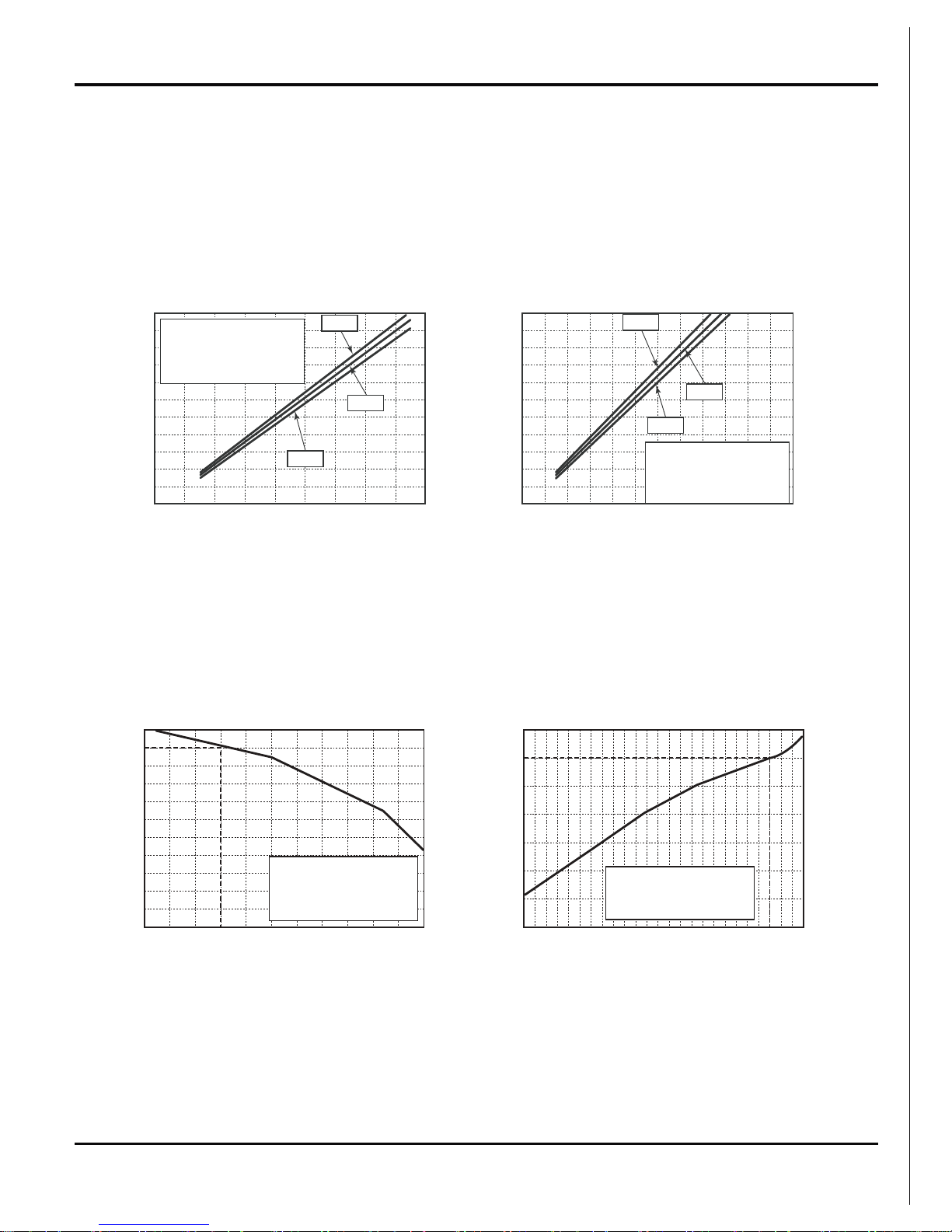
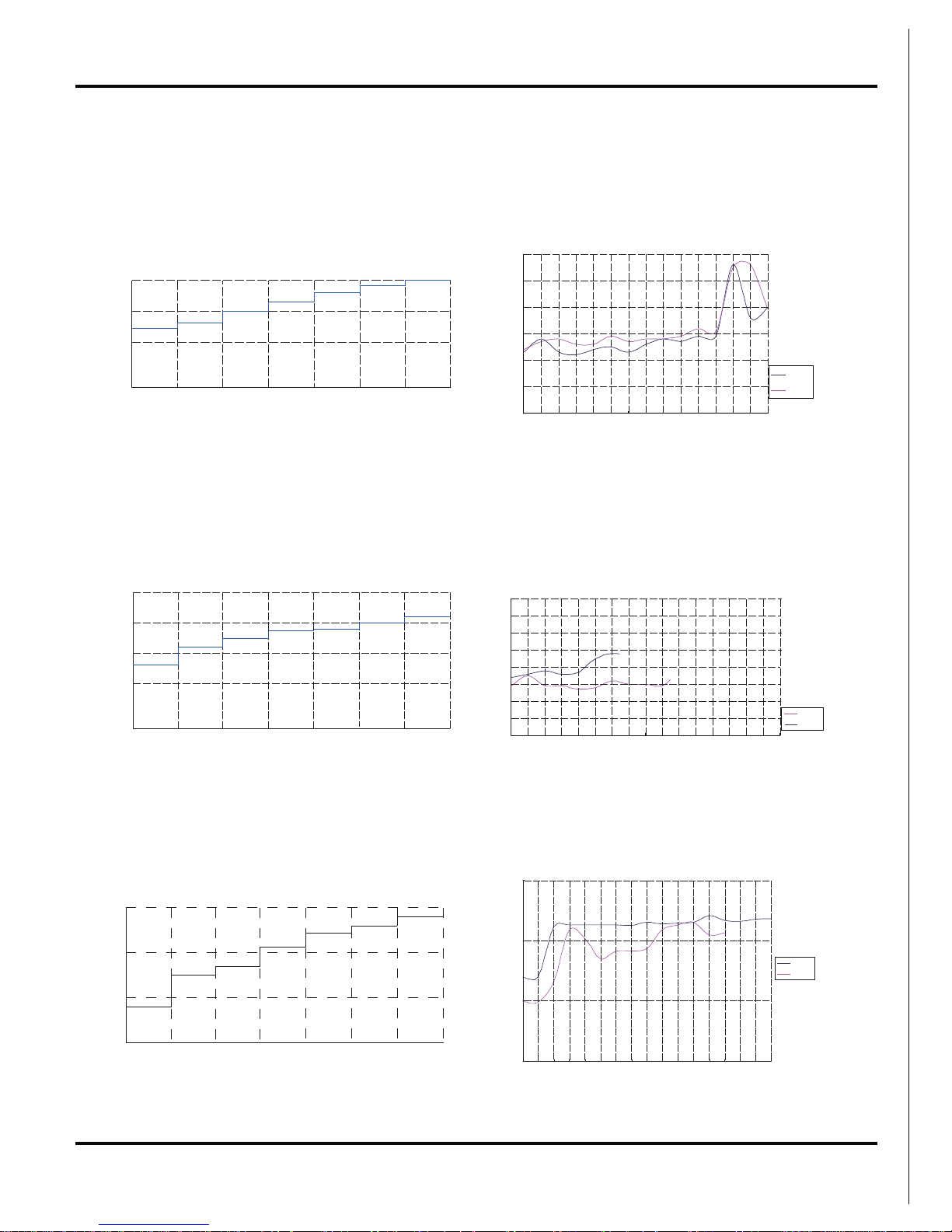
2.2 Operation Characteristic Curve
gnitaehgnilooc
2.3 Capacity Variation Ratio According to Temperature
gnitaehgnilooc
32 33 34 35 36 37 38 39 43 –15 –10 –5 0 5 7 10
40 41 42
100
105
95
90
85
80
75
70
65
60
55
50
Outdoor temp.Û&
%(oitaryticapa&
110
100
90
80
70
60
50
40
Outdoor temp.Û&
%(oitaryticapa&
&RQGLWLRQV
Indoor :'%Û&:%Û&
Indoor air flow : High
Pipe length : 5m
&RQGLWLRQV
Indoor :'%Û&:%Û&
Indoor air flow : High
Pipe length : 5m
009070605040302010 110210010908070605040302010
80
11
10
9
8
7
6
5
4
3
2
1
0
A(tnerru&
11
10
9
8
7
6
5
4
3
2
1
0
A(tnerru&
&RQGLWLRQV
Indoor :'%Û&:%Û&
Outdoor :'%Û&:%Û&
Indoor air flow : High
Pipe length : 5m
&RQGLWLRQV
Indoor :'%Û&:%Û&
Outdoor :'%Û&:%Û&
Indoor air flow : High
Pipe length : 5m
220V
230V
240V
220V
230V
240V
zH(ycneuqerfrosserpmo&zH(ycneuqerfrosserpmo&
8
Specifications
2.4 Operation Data
Cooling
Heating
09K
Standard
pressure
Indoor Outdoor P(MPa)
T1(ć)T2(ć)
27/19 35/24 09k 0.9 to 1.1 12 to 14 70 to 40 Super High High 52
Heat exchanger pipe temp
Indoor fan
mode
Outdoor fan
mode
Compressor
revolution(rps)
Temperature condition
(ć)
Model
name
Standard
pressure
Indoor Outdoor P(MPa)
T1(ć)T2(ć)
20/- 7/6 09k 2.2 to 2.4 70 to 35 2 to 4 Super High High 65
Temperature condition
(ć)
Model
name
Heat exchanger pipe temp
Indoor fan
mode
Outdoor fan
mode
Compressor
revolution(rps)
12K
Cooling
Heating
Standard
pressure
Indoor Outdoor P(MPa)
T1(ć)T2(ć)
27/19 35/24 12k 0.9 to 1.1 12 to 14 70 to 40 Super High High 72
Heat exchanger pipe temp
Indoor fan
mode
Outdoor fan
mode
Compressor
revolution(rps)
Temperature condition
(ć)
Model
name
Standard
pressure
Indoor Outdoor P(MPa)
T1(ć) T2(ć)
20/- 7/6 12k 2.2 to 2.4 70 to 35 2 to 4 Super High High 77
Temperature condition
(ć)
Model
name
Heat exchanger pipe temp
Indoor fan
mode
Outdoor fan
mode
Compressor
revolution(rps)
Standard
p
ressure
Indoor Outdoor P(MPa) T1(ć)T2(ć)
27/19 35/24 18k 0.9 to 1.1 12 to 14 70 to 40 Super High High 70
T
emperature con
diti
on
(ć)
Heat
exchanger pipe
tem
p
Indoor fan
mode
Outdo or fan
mode
Compressor
revolution(rp
s)
Model
name
Standard
press ure
Indoor Outdoor P(MPa) T1(ć)T2(ć)
20/- 7/6 18k 2.2 to 2.4 70 to 35 2 to 4 Super High High 64
Outdo or fan
mode
Compressor
revolution(rp
s)
Temperature condition
(ć)
Model
name
Heat exchanger pipe
tem p
Indoor fan
mode
18K
NOTES :
T1: Inlet and outlet pipe temperature of evaporator.
T2: Inlet and outlet pipe temperature of condenser.
P: Pressure of air pipe connecting indoor and outdoor units.
Cooling
Heating
9
Specifications
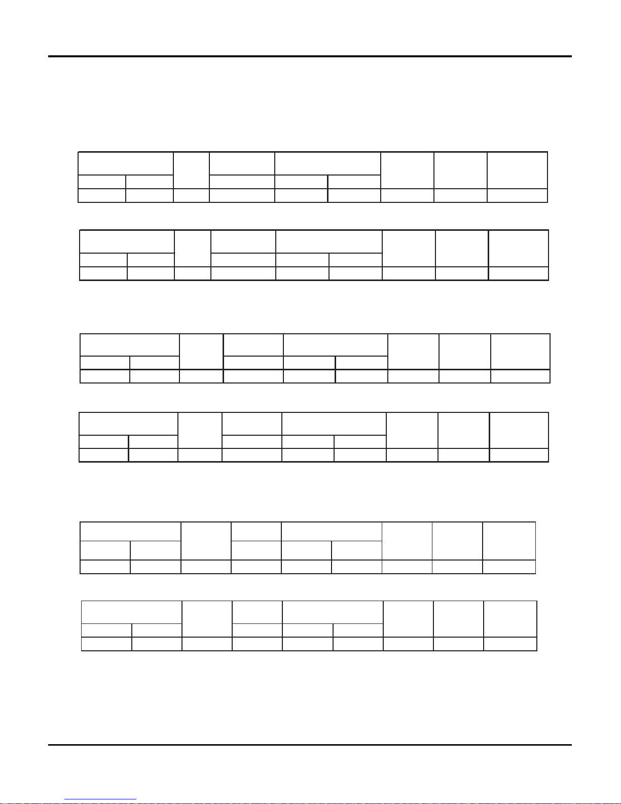
2.5 Noise criteria curve tables for both models
09K
12K
18K
Indoor fan motor rotating speed
Indoor side noise when blowing
s L LM M HM H SH
20
30
40
50
20
30
40
Indoor side noise when blowing
Indoor fan motor rotating speed
SH
H
HM M LM L S
L
46
47
48
49
50
51
52
15 20 25 30 35 40 45 50 55 60 65 70 75 80 85
Compress or frequency
˄Hz˅
Noise dB(A)
Cooling
Heating
30.0
40.0
50.0
60.0
15 20 25 30 35 40 45 50 55 60 65 70 75 80 85 90 94
Compress or frequency
˄Hz˅
Noise/dB(A)
Cooling
Heating
45
46
47
48
49
50
51
52
53
1234567891011121314151617
Compres sor frequency(Hz)
Noise dB(A)
Cooling
Heating
Indoor side noise when blowing
Indoor fan motor rotating speed
SH HHMMLM L S
L
20
30
40
50
10
Constrction views
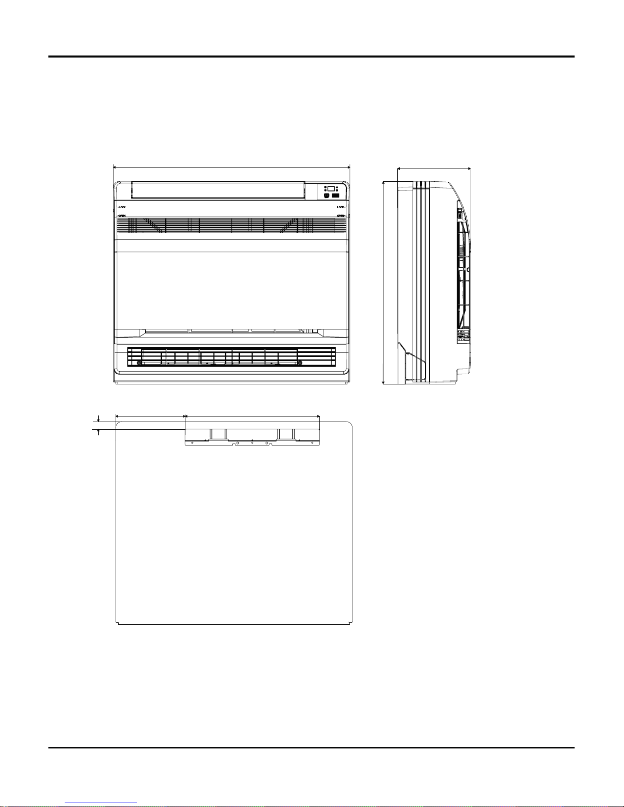
3. Construction Views
3.1 Indoor Unit
Unit:mm
700
215
600
398
205
22
11
Constrction views
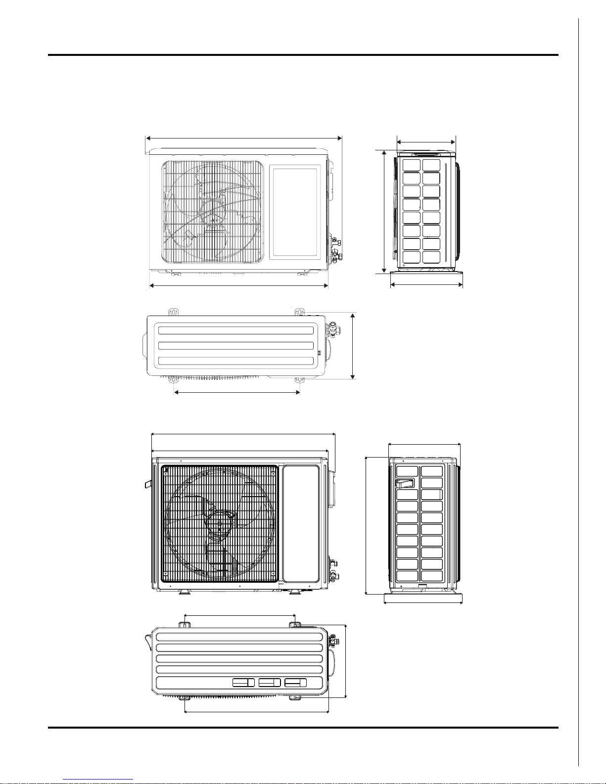
364
930
896
695
396
560
368
730
3.2 Outdoor Unit
09K 12K
Unit:mm
18K
Unit:mm
848
320
540
540
766
276
286
12
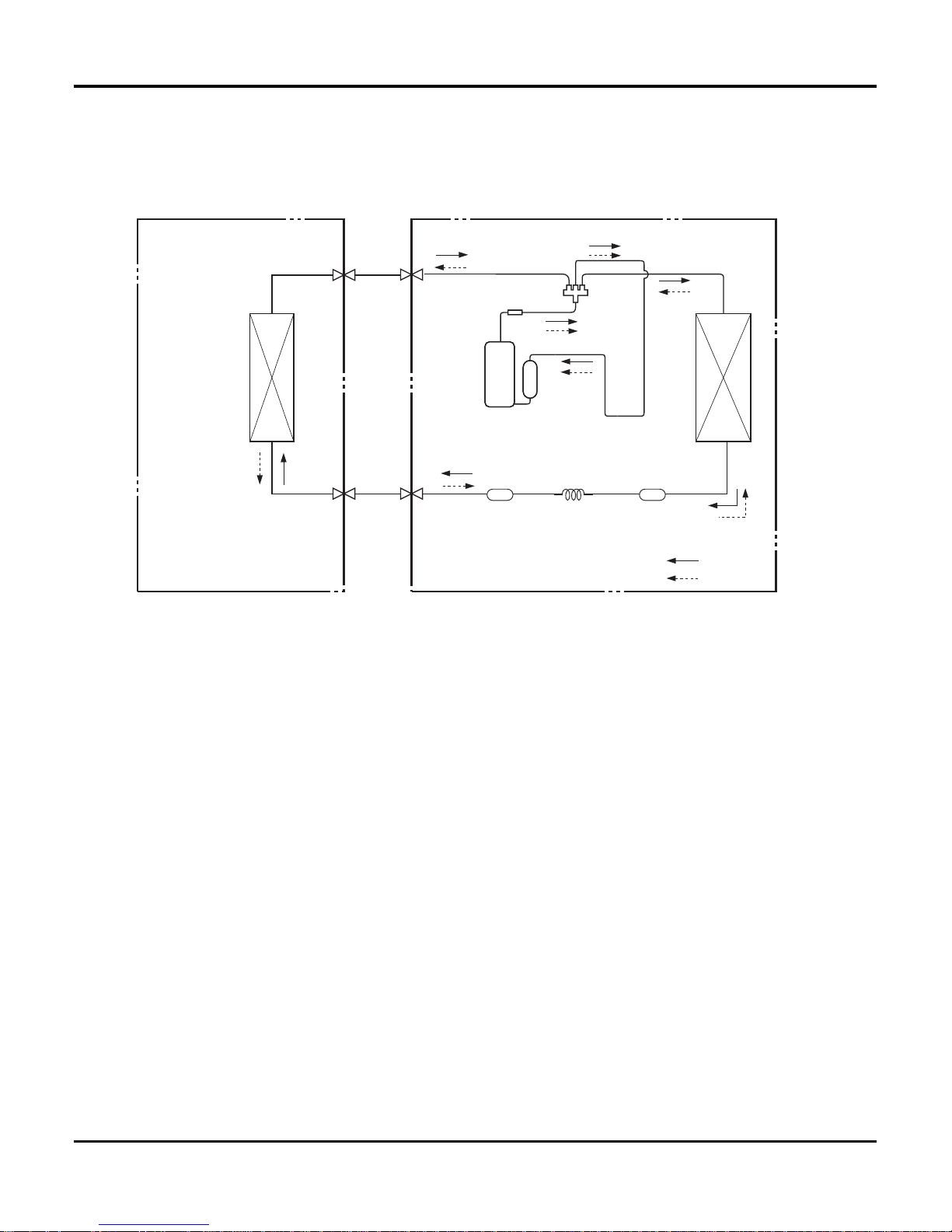
Refrigerant System Diagram
4. Refrigerant System Diagram
INDOOR UNIT OUTDOOR UNIT
HEAT
EXCHANGE
(EVAPORATOR)
HEAT
EXCHANGE
(CONDENSER)
COMPRESSOR
GAS SIDE
3-WAY VALVE
LIQUID SIDE
2-WAY VALVE
COOLING
HEATING
Accumlator
Discharge
Suction
Muffler
4-Way valve
CapillaryStrainer Strainer
Refrigerant pipe diameter
18K
Liquid : 1/4" (6 mm)
Gas : 1/2" (12 mm)
Refrigerant pipe diameter
09K 12K
Liquid : 1/4" (6 mm)
Gas : 3/8" (9.52 mm)
13
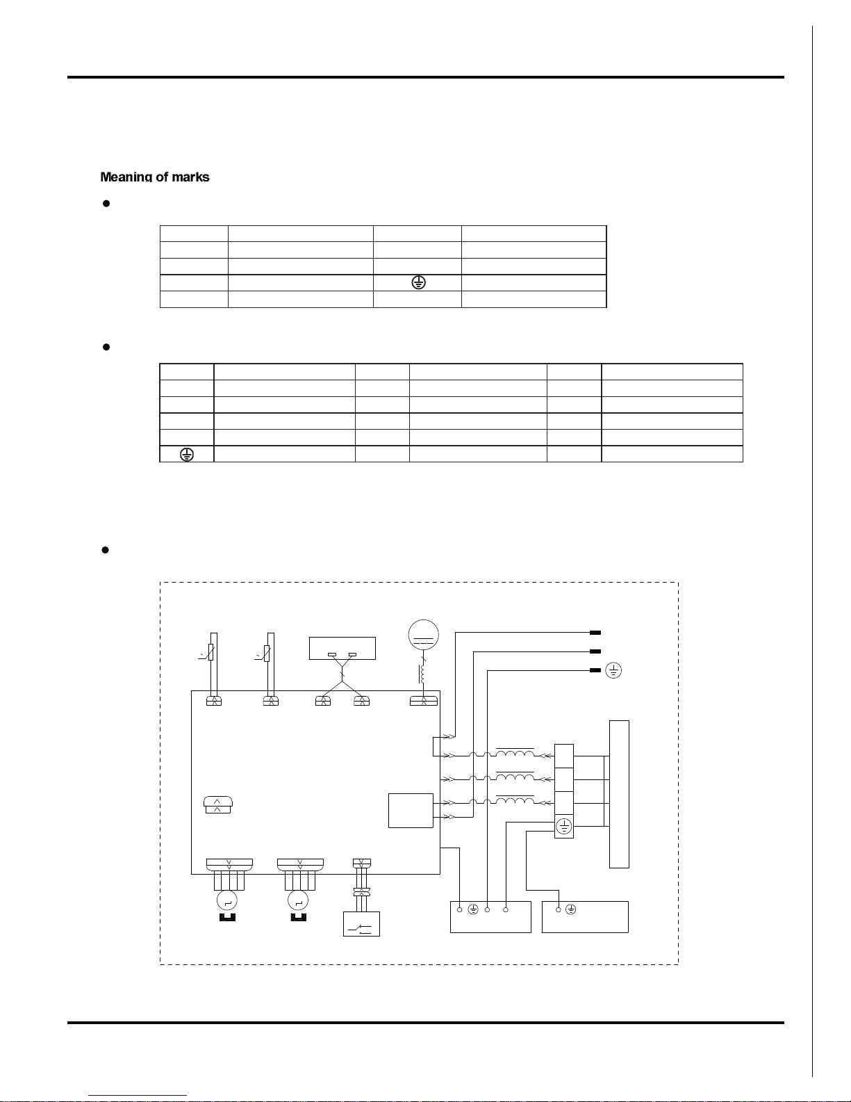
Schematic Diagram
5. Schematic Diagram
5.1 Electrical Data
5.2 Electrical wiring
Outdoor Unit
Indoor Unit
Indoor Unit
Symbol Color symbol Symbol Color symbol
NWORBNBEULBUB
YE YELLOW
RD RED
BK BLACK
YEGN YELLOW GREEN
PROTECTIVE EARTH
Symbol Parts name Symbol Color symbol Symbol Color symbol
C1 CBB61 BN BROWN WH WHITE
C2 CBB65 BU BLUE YE YELLOW
SAT OVERLOAD BK BLACK RD RED
COMP COMPRESSOR OG ORANGE YEGN YELLOW GREEN
PROTECTIVE EARTH WH WHITE
YEGN
BK
BU
M1
SWING-DOWN
OUTDOOR UNIT
CAP
JUMP
AP1 PRINTED CIRCUIT BOARD
ROOM
RT2
RT1
TUBE
SENSOR
SENSOR
ROOM
TUBE
POWER
BU(WH)
N
DISPLAY
RECEIVER AND
DISPLAY BOARD
DISP2
AP2
DISP1
FAN
DC-MOTOR
MOTOR
TEMP.
TEMP.
STEPPING
SWING-UP
M2
AP3
S
CN8
SELECT
SWITCH
MOTOR
STEPPING
MOTOR
BN(BK)
YEGN(GN)
N(1)
2
XT
3
BN
COM-OUT
L-OUT
AC-L
BU
BK
BN
PE
EVAPORATOR
YEGN
K7
TERMINAL
BLOCK
MAGNETIC
RING
L1
L1
L1
E
ELECTRIC BOX
PE
YEGN
YEGN
5
L2
MAGNETIC
RING
0
0
L
N
M3

14
Schematic Diagram
Outdoor Unit
09K 12K
18k
These circuit diagrams are subject to change without notice, please refer to the one supplied with the unit.
BKWH
0
0
0
R(U)
S(V)
CN2
YEGN
AC-L1
N1
YEGN
BU
E
BN
BK
C(W)
PE
PE
PE
COMU
RT1
RT2
RT3
BU
YE RD
OVC-COMP
RD
RD
SAT
YEGN
COMP
BK
BN
BU
N3N2
TERMINAL
COMP.
COMP-U
COMP-V
COMP-W
LX-2
OG
WH
LX-1
L
OUTTUBE
TEMP. SENSOR
OUTROOM
TEMP. SENSOR
EXHAUST
TEMP. SENSOR
4YV
4V
FAN MOTOR
PE
BLOCK
4-WAY
VALVE
PE
PE
YEGN
REACTOR
L1
L1
L2
L2
L2
AC-L2
OFAN
OFAN-BRW OFAN-RED
BU
L3
L3
BU
(BK)
BN
RD
PROTECTOR
OVERLOAD
INDOOR UNIT
XT
AP1 PRINTED CIRCUIT BOARD
N(1)
2
3
VT
VT
M
BKWH
0
0
0
R(U)
S(V)
T-SENSOR
YEGN
AC-L
N
YEGN
BU
PE
BN
BK
BU
YE
RD
C(W)
PE
PE
PE
COM-INNER
RT1
RT2
RT3
YE
BU RD
OVC-COMP
WHWH
SAT
YEGN
M
BK
BN
BU
PFCC2
YE
PFCC1
CAP.
X1
TERMINAL
YE
COMP.
COMP-U
COMP-V
COMP-W
INDC2
OG
WH
INDC1
L
OUTTUBE
TEMP. SENSOR
OUTROOM
TEMP. SENSOR
EXHAUST
TEMP. SENSOR
FAN
M
HALL OFAN
4YV
4V
MOTOR
PE
BLOCK
4-WAY
VALVE
PE
PE
YEGN
REACTOR
OVERLOAD
PROTECTOR
INDOOR UNIT
XT
AP1 PRINTED CIRCUIT BOARD
N(1)
2
3
15
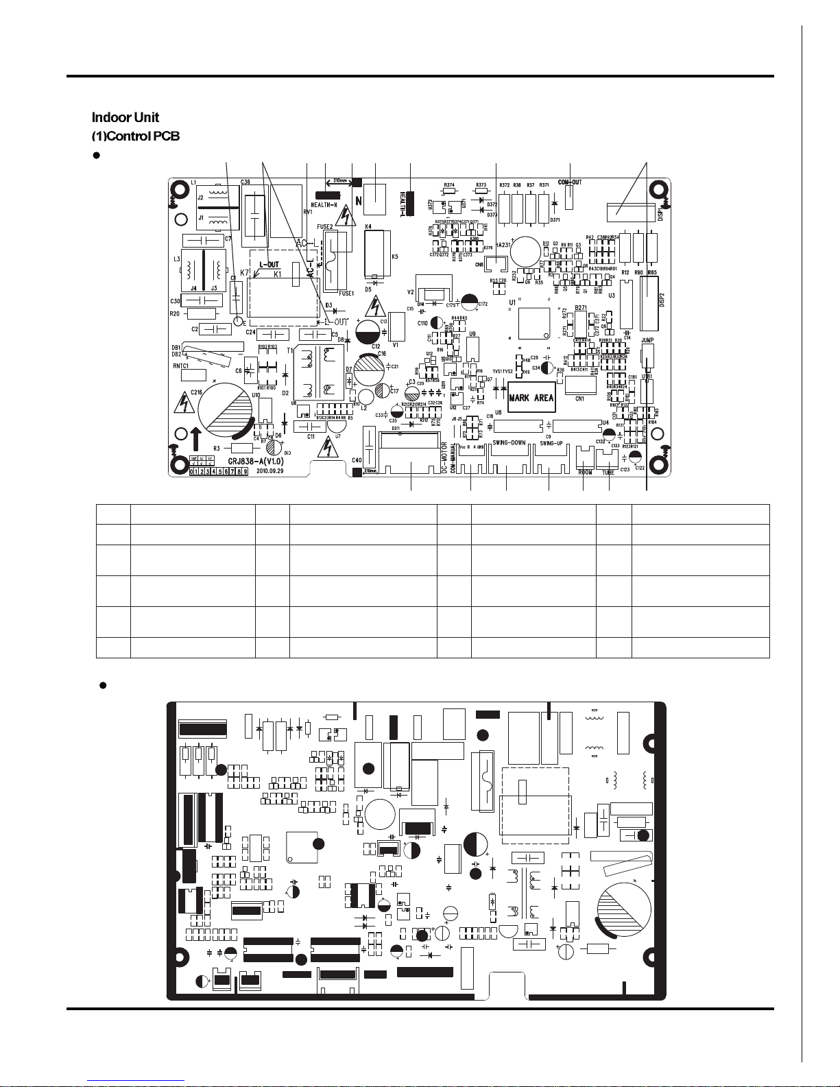
Schematic Diagram
5.3 Printed Circuit Board
TOP VIEW
12 34567 8 9 10
11121314151617
BOTTOM VIEW
No. Name No. Name No. Name No. Name
1 Earthing wire 6 Neutral wire input 11 Jumper cap interface 16 Wire controller interface
2
Outdoor power supply
interface
7
Health function live wire
interface
12
Indoor tube
temperature sensor
17 DC fan interface
3
Live wire input
interface
8
Lower swing control
interface
13
Indoor ambient
temperature sensor
18 /
4
Health function
neutral wire interface
9
Communication interface
of indoor and outdoor unit
14 Upper swing interface 19 /
5 Fuse 10 Display board interface 15 Lower swing interface 20 /
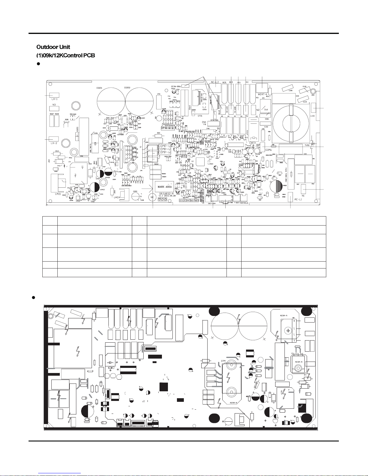
16
Schematic Diagram
TOP VIEW
1
2
3
4
5
6
78 9
10
11
14 12 13
15
BOTTOM VIEW
No. Name No. Name No. Name
1 Power supply neutral wire input 6 Fan interface 11 Electric heating belt live wire
2 Power supply live wire input 7
Chassis electric heating belt
neutral wire
12 Overload input
3 Communication interface 8
Compressor electric heating belt
neutral wire
13 Temperature sensor
4 Reactor interface 1 9 4-way valve neutral wire 14 Compressor three phases U, V, W
5 Reactor interface 2 10
4-way valve live wire
15 Power supply earthing wire input
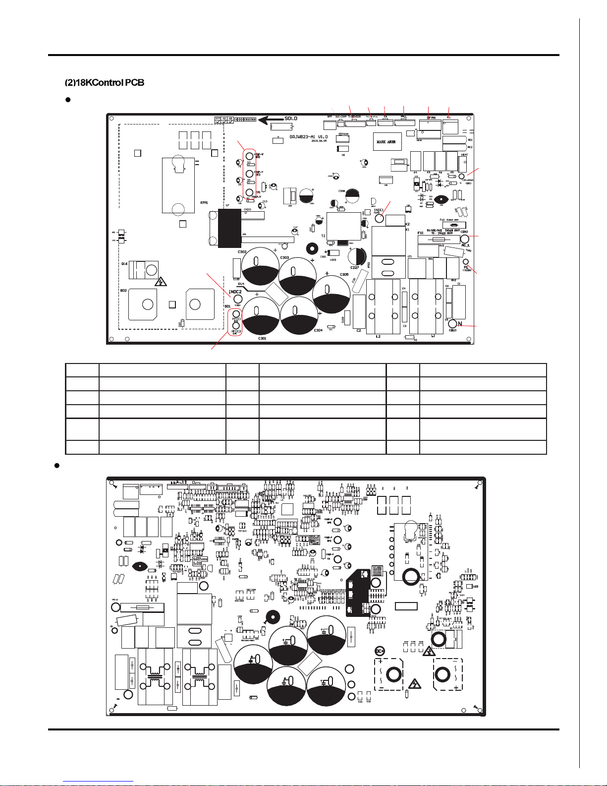
17
Schematic Diagram
BOTTOM VIEW
15
13
14
1
2345678
9
10
11
12
NO. Interface name NO. Interface name NO. Interface name
1 Interface of compressor 6 Fan HALL interfzce
11
Earthing wire
2 Overload protector of compressor 7 Outdoor fam 12 Neutral wire
3 Temperature sensor 8 Four-way valve 13 Interface 1 of reactor
49
Communication interface for indoor
unit
14 PFC capacitor interface
5 Electron expansion valve 10 Live wire 15 Interface 2 of reactor
TOP VIEW
Outdoor tube temperature sensor
 Loading...