

Vivax ACP-18COFM50AEEI User Manual
Upute za uporabu
User manual
ACP-18COFM50AEEI
RoHS
14

ENG
User
manual
RoHS
14
ACP-18COFM50AEEI
CONTENTS
SOCIABLE REMARK
Sociable remark ....................................................................................................................................................2
SAFETY PRECAUTIONS
Warning ............................................................................................................................................................... 3
Caution ................................................................................................................................................................ 4
OPERATING INSTRUCTIONS
Identification of parts ............................................................................................................................................ 5
Operating temperature ....................................................................................................................................... 12
Manual operation ............................................................................................................................................... 12
Airflow direction control ..................................................................................................................................... 13
How the air conditioner works ........................................................................................................................... 14
CARE AND MAINTENANCE
Care and maintenance ........................................................................................................................................ 16
OPERATIONTIPS
Operation tips ....................................................................................................................................................... 18
TROUBLESHOOTING TIPS
Troubleshooting tips ........................................................................................................................................... 20
CAUTION
Contact an authorised service technician for repair or maintenance of this unit.
Contact the installer for installation of this unit.
The air conditioner is not intended for use by young children or invalids without supervision.
Young children should be supervised to ensure that they do not play with the air conditioner.
If the power cord is to be replaced, replacement work shall be performed by authorised personnel only.
Installation work must be performed in accordance with the national wiring standards by authorised
personnelonly.
SOCIABLE REMARK
When using this air conditioner in the European countries, the follow information must be followed:
DISPOSAL: Do not dispose this product as unsorted municipal waste. Collection of such waste separately
for special treatment is necessary.
It is prohibited to dispose of this appliance in domestic household waste.
For disposal, there are several possibilities:
A) The municipality has established collection systems, where electronic waste can be disposed of at least
free of charge to the user.
B) When buying a new product, the retailer will take back the old product at least free of charge.
C) The manufacture will take back the old appliance for disposal at least free of charge to the user.
D) As old products contain valuable resources, they can be sold to scrap metal dealers.
Wild disposal of waste in forests and landscapes endangers your health when hazardous substances leak
into the ground-water and find their way into the food chain.
2
SAFETY PRECAUTIONS
To prevent injury to the user or other people and property damage, the following instructions must be
followed. Incorrect operation due to ignoring of instructions may cause harm or damage.
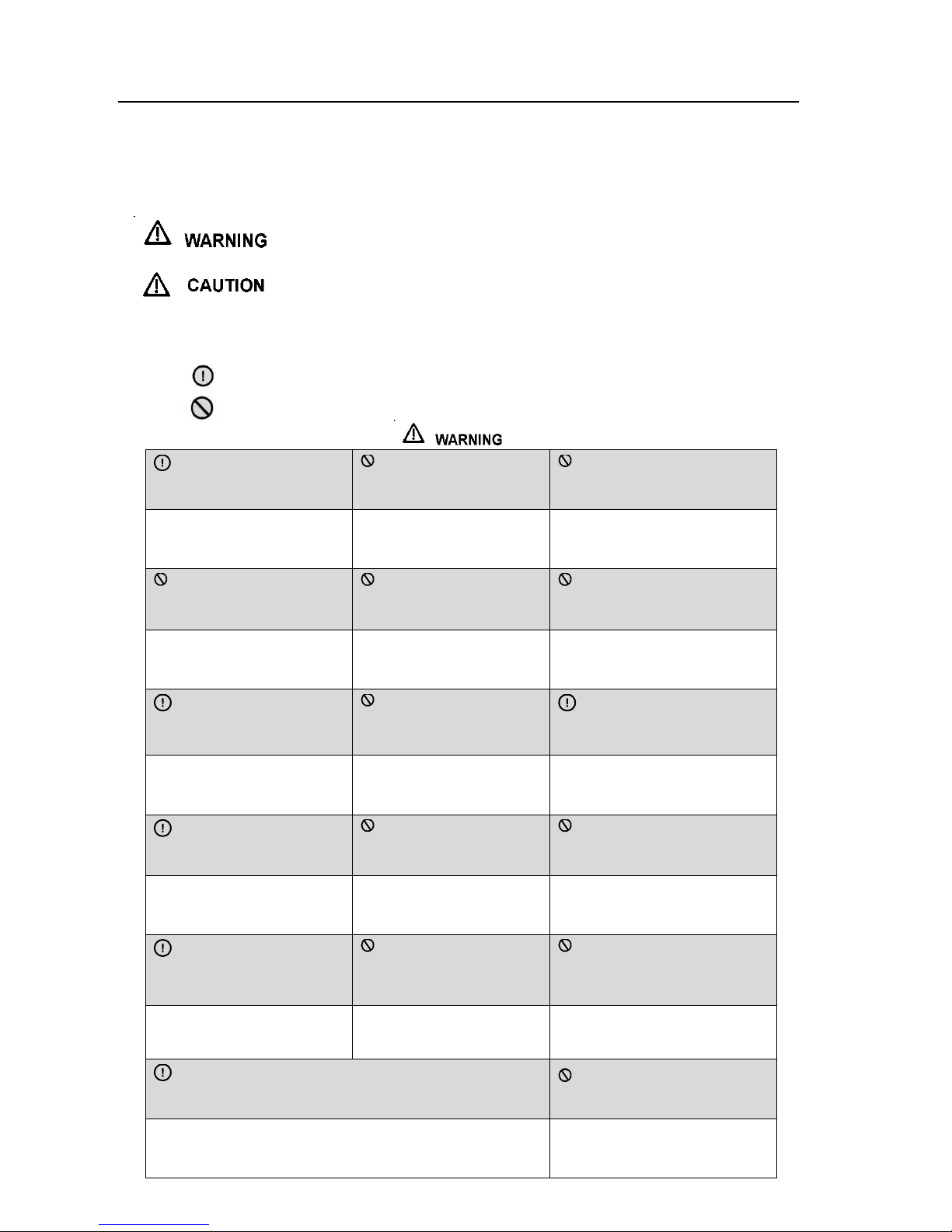
■ The seriousness is classified by the following indications.
This symbol indicates the possibility of death or serious injury.
This symbol indicates the possibility of injury or damage to property
■ Meanings of symbols used in this manual are as shown below.
Never do this.
Always do this.
Connect with the power
properly.
Do not operate or stop
the unit by switching on or
off the power.
Do not damage or use an
unspecified power cord.
Otherwise, it may cause
electric shock or fire due to
excess heat generation.
It may cause electric shock
or fire due to heat
generation.
It may cause electric shock or fire.
Do not modify power cord
length or share the outlet with
other appliances
Do not operate with wet
hands or in damp
environment.
Do not direct airflow at
roomoccupants only.
It may cause electric shock or
fire due to heat generation.
It may cause electric shock.
This could damage your health.
Always ensure effective
grounding.
Do not allow water to run
into electric parts.
Always install circuit
breaker and a dedicated
power circuit.
No grounding may cause
electric shock.
It may cause failure of
machine or electric shock.
No installation may cause fire
and electric shock.
Disconnect the power if
strange sounds, smell, or
smoke comes fromit.
Do not drink water
drained from air conditioner.
Do not open the unit
during operation.
It may cause fire and electric
shock.
It contains contaminants and
could make you sick.
It may cause electric shock.
Use the correctly rated
breaker or fuse.
Do not use the power
cord close to heating
appliances
Do not use the power cord
near flammable gas or
combustibles, such as gasoline,
benzene, thinner, etc.
There is risk of fire or electric
shock.
It may cause fire and electric
shock.
It may cause an explosion or fire.
Ventilate roombefore operating air conditioner if there is a
gas leakage from another appliance.
Do not disassemble
or modify unit.
It may cause explosion, fire and, burns.
It may cause failure and electric
shock.
3
CAUTION
When the air filter is to be
removed, do not touch the
metal parts of the unit.
Do not clean the air
conditioner with water.
Ventilate the room well
when used together with a
stove, etc.
It may cause an injury.
Water may enter the unit and
degrade the insulation. It may
cause an electric shock.
An oxygen shortage may
occur.
When the unit is to be
cleaned, switch off, and turn
off the circuit breaker
Do not put a pet or house plant
where it will be exposed to direct
air flow.
Do not use for special
purposes.
Do not clean unit when
power is on as it may cause fire
and electric shock, it may cause
an injury.
This could injure the petor plant.
Do not use this air
conditioner to preserve
precision devices, food,
pets, plants, and art
objects. It may cause
deterioration of quality, etc.
Stop operation and close
the window in storm or
hurricane.
Do not place obstacles around
air-inlets or inside of air-outlet
Turn off the main power
switch when not using the
unit for a long time.
Operation with windows
opened may cause wetting of
indoor and soaking of
household furniture.
It may cause failure of
appliance or accident.
It may cause failure of
product or fire.
Do not use strong detergent
such as wax or thinner. Use
a soft cloth for cleaning.
Ensure that the installation bracket of
the outdoor appliance is not damaged due to
prolonged exposure.
Always insert the filters
securely. Clean filter once
every two weeks.
Appearance may be
deteriorated due to change of
product color or scratching of its
surface.
If bracket is damaged, there is
concern of damage due to falling
of unit.
Operation without filters
may cause failure.
Do not place heavy object
on the power cord and take
care so that the cord is not
compressed.
Use caution when unpacking
and installing. Sharp edges
could cause injury.
If water enters the unit,
turn the unit off and
disconnect the power,
contact a qualified service
technician.
Do not operate your air
conditioner in a wet room such
as a bathroom or laundry room.
Children should be supervised
to ensure that they do not play
with the appliance.
There is danger of fire
or electric shock.
This appliance can be used
by children aged from 8 years
and above and persons with
reduced physical, sensory or
mental capabilities or lack of
experience and knowledge if
they have been given
supervision or instruction
concerning use of the
appliance in a safe way and
understand the hazards
involved. Children shall
not play with the appliance.
Cleaning and user maintenance
shall not be made by children
without supervision.
This appliance is not intended
for use by persons (including
children) with reduced physical,
sensory or mental capabilities,
or lack of experience and
knowledge, unless they have
been given supervision or
instruction concerning use of the
appliance by a person
responsible
for their safety.
If the supply cord is
damaged, it must be
replaced by the
manufacturer, its service
agent or similarly qualified
persons in order to avoid a
hazard.
4
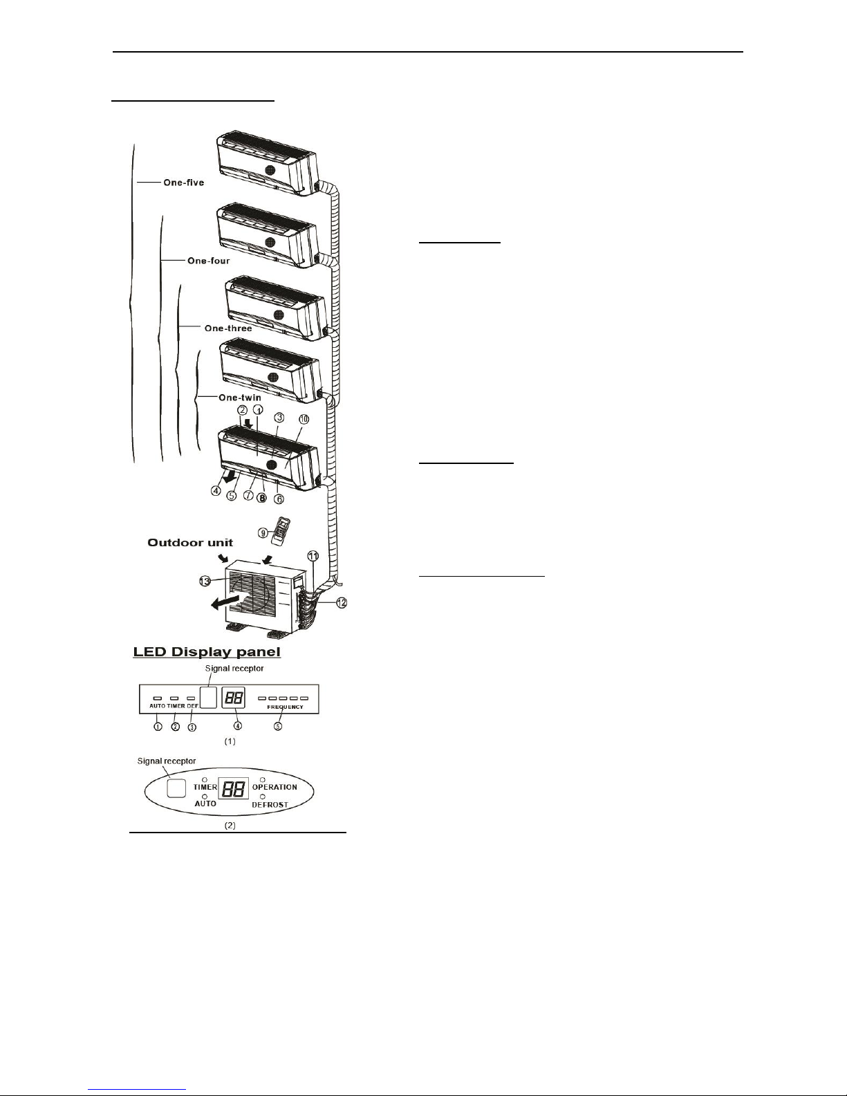
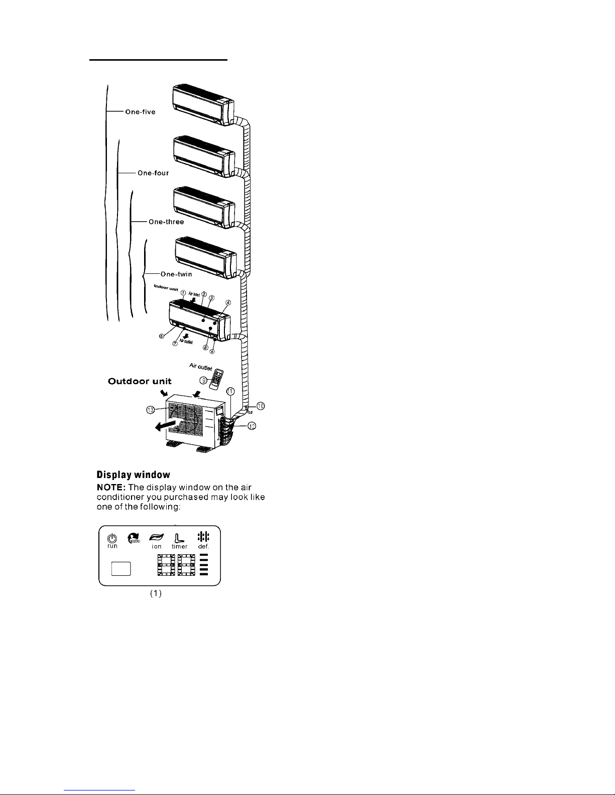
Identification of parts
IMPORTANT:
• For multi-split type air conditioner, one outdoor unit can
match different types of indoor units. So all the pictures
in this manual are for explanation purpose only. Your
air conditioner may be slightly different. The actual
shape shall prevail.
• The following pages introduce several kinds of indoor
units matching with the outdoor units.
Indoor unit
1. Front panel
2. Top air intake
3. Air filter(Inside)
4. Air outlet
5. Horizontal air flow louver
6. Vertical air flow louver(Internal)
7. Display panel
8. LED display window
9. Remote controller
10. Manual control button(Behind the front panel)
Outdoor unit
11. Refrigerant connecting pipe, drain hose and
electric wiring
12. Stop valve
13. Air outlet
Display panel
AUTO indication lamp
Lights up during the Auto operation.
TIMER indication lamp
Lights up during Timer operation.
DEFROST indication lamp
(For Cooling & Heating models only): Lights up when the
air conditioner starts defrosting automatically or when the
warm air control feature is activated in heating operation.
DIGITAL DISPLAY indication lamp
Displays the current setting temperature. Only when the
air conditioner is in FAN operation, it displays the actual
room temperature. And displays the malfunction code or
protection code.
OPERATION indication lamp
This indicator appears only when the compressor is in
operation and indicates the current operating frequency.
Indoor unit
OPERATING INSTRUCTIONS
5
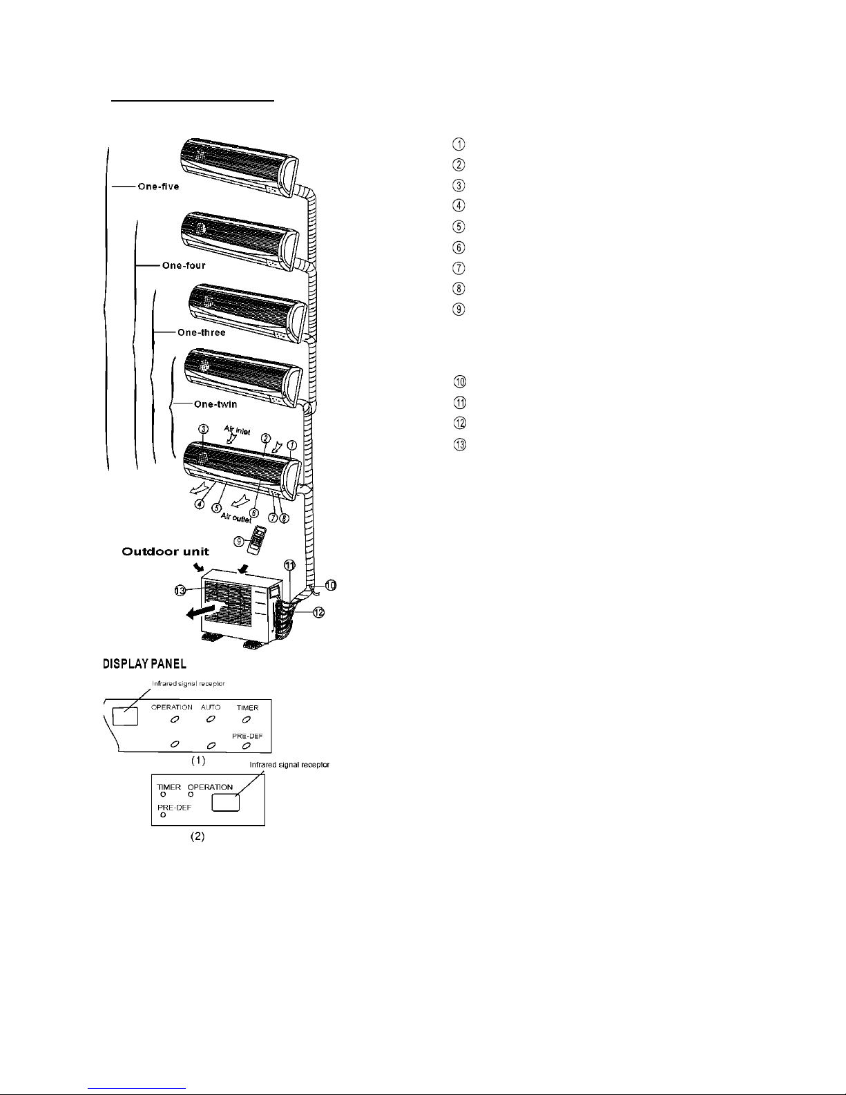
Identification of parts
Indoor unit
Indoor unit
Front panel frame
Front panel
Air filter
Horizontal air flow grille
Vertical airflow louver
Room temperature sensor
Display panel
Infrared signal receiver
Remote controller
Outdoor unit
Drain hose, refrigerant connecting pipe
Connective cable
Stop valve
Fan hood
DISPLAYPANEL
OPERATION indicator:
The indicator flashes once every second after
power is on and illuminates when the air conditioner
is in operation.
TIMER indicator:
The indicator illuminates when TIMER is set ON.
PRE-DEF. Indicator
(For cooling& heating model only):
This indicator illuminates when the air conditioner
starts defrosting automatically or when the Anti-cold
air function is activated in heating operation.
AUTO indicator:
This indicator flashes when the air conditioner is in
AUTO operation.
6
Identification of parts
Indoor unit
Indoor unit
© Front panel frame
© Front panel
© Air filter
© Horizontal air flow grille
© Vertical airflow louver
© Room temperature sensor
© Display panel
© Remote controller
Outdoor unit
® Drain hose, refrigerant connecting pipe
© Connective cable
© Stop valve
© Fan hood
LED DISPLAY WINDOW
① AUTO indication lamp
Lights up during the Auto operation.
② TIMER indication lamp
Lights up during Timer operation.
③ DEFROST indication lamp
(For Cooling & Heating models only): Lights up
when the air conditioner starts defrosting
automatically or when the warm air control feature
is activated in heating operation.
DIGITAL DISPLAY indication lamp
Displays the current setting temperature. Only when
the air conditioner is in FAN operation, it displays the
actual room temperature. And displays the
malfunction code or protection code.
OPERATION indication lamp
This indicator appears only when the
compressor is in operation and indicates the
current operating frequency.
7
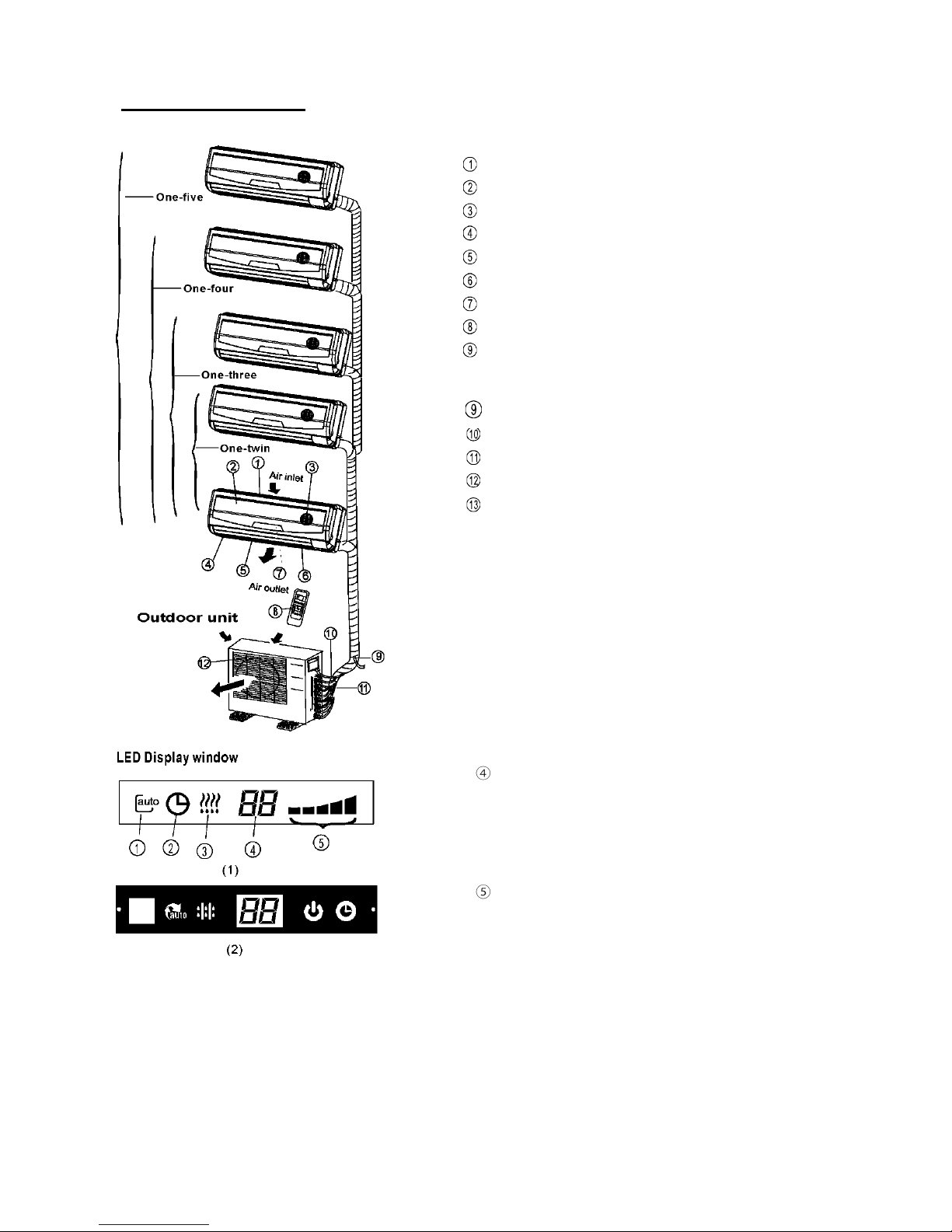
Identification of parts
Indoor unit
Indoor unit
1. Panel frame
2. Rear air intake grille
3. Front panel
4. Air Purifying filter & Air filter(behind)
5. Horizontal louver
6. LCD display window
7. Vertical louver
8. Manual control button(behind)
9. Remote controller holder
Outdoor unit
10. Drain hose, refrigerant connecting pipe
11. Connective cable
12. Stop valve
13. Fan hood
8
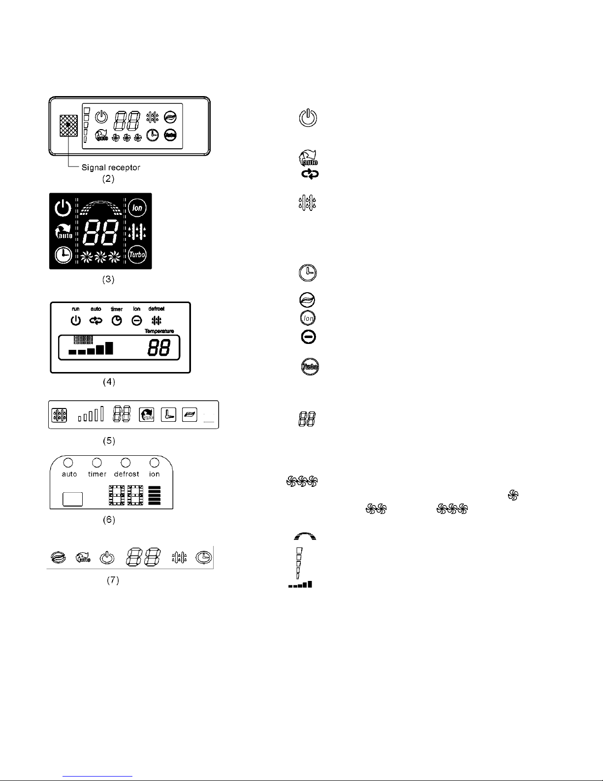
OPERATION display
Displayed when the air conditioner is in operation.
AUTO operation display
Displayed during Auto operation.
DEFROST operation display
(For Heating & Cooling model only):
Displayed when the air conditioner starts defrosting
automatically or when the warm air control feature is
activated in heating operation.
TIMER display
Displayed during Timer operation.
CLEAN AIR display (optional)
Displayed when CLEAN AIR feature is activated.
TURBO operation display
Displayed when select TURBO function on cooling
operation or on heating operation.
DIGITAL DISPLAY
Displays the current setting temperature when the air
conditioner is in operation.
FAN SPEED display
Displayed the selected fan speed: LOW( ),
MED( )and HIGH ( ).
Frequency indication lamp
This display is separated into five zones. The zones
illuminate based on the compressor current
frequency. For example, higher frequency will
illuminate more zones.
9
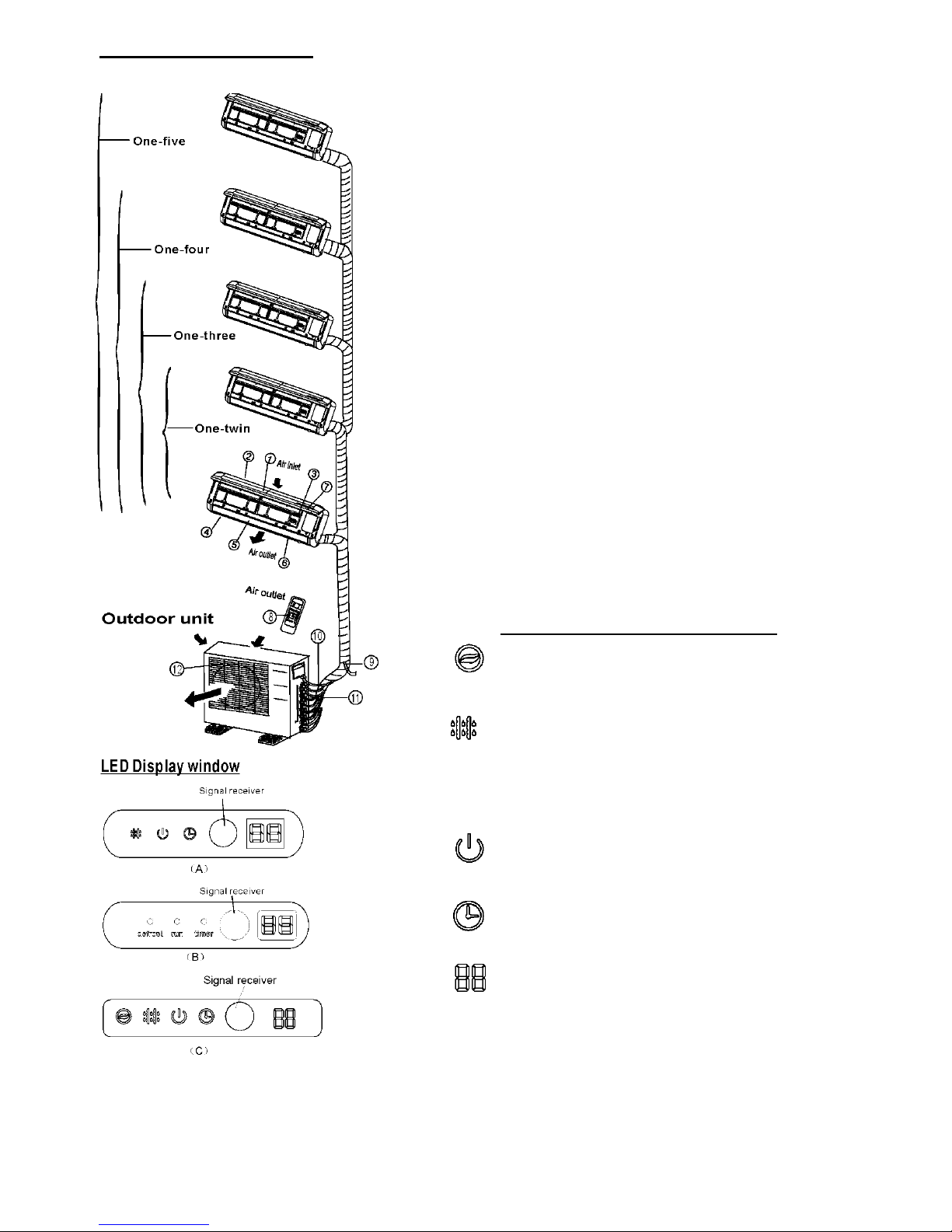
Identification of parts
Indoor unit
Indoor unit
1. Front panel
2. Air inlet
3. Air filter
4. Air outlet
5. Horizontal air flow grille
6. Vertical air flow louver(inside)
7. Display panel
8. Remote control
NOTE: The actual shape of the indoor unit you purchased
may be slight different on front panel and display window.
Outdoor unit
9. Drain hose, refrigerant connecting pipe
10. Connective cable
11. Stop valve
12. Fan hood
NOTE:
All the pictures in this manual are for explanation purposes
only. Your air conditioner may be slightly different. The
actual shape shall prevail.
Indication lamp on LED Display window
ION indication lamp (optional function)
This lamp illuminates when Clean Air feature is activated.
DEFROST indication lamp
(Enabled on cooling & heating models only):
Lights up when the air conditioner starts defrosting
automatically or when the warm air control feature
is activated in heating operation.
OPERATION indication lamp
This lamp illuminates when the air conditioner is in
operation.
TIMER indication lamp
Lights up during timer operation.
Temperature indicator
• Displays the temperature settings when the
air conditioner is operational.
•Displays the malfunction code.
10
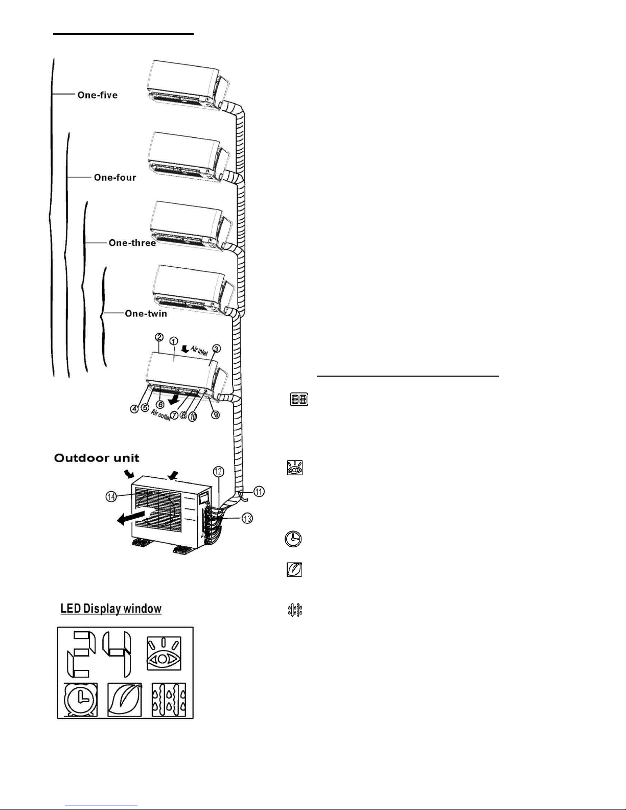
Identification of parts
Indoor unit
Indoor unit
1. Front panel
2. Air inlet
3. Air filter(inside)
4. Air outlet
5. Horizontal air flow grille(outside)
6. Horizontal air flow grille(inside)
7. Vertical airflow louver
8. Display panel
9. Manual control button and receiver
10. Intelligent eye detector(on some models)
Outdoor unit
11. Drain hose, refrigerant connecting pipe
12. Connective cable
13. Stop valve
14. Fan hood
NOTE:
All the pictures in this manual are for explanation purposes
only. Your air conditioner may be slightly different. The
actual shape shall prevail.
Indication lamp on LED Display window
TEMPERATURE indication lamp
Displays the temperature settings when the air conditioner
is operational. Displays the malfunction code. Displays the
actual room temperature on Fan only mode.
INTELLIGENT EYE indication lamp
(Optional)
Lights up during Intelligent eye operation except when the
machine is defrosting. This indication lamp continues
flashing when the unit detects human activity.
T.IMER indication lamp
Lights up during Timer operation.
ION indication lamp (optional)
Lights up when Clean Air feature is activated.
DEFROST indication lamp
(Enabled on cooling & heating models only): Lights up when
the air conditioner starts defrosting automatically or when
the warm air control feature is activated in heating
operation.
11
NOTE: This manual does not include Remote Controller Operations, see the
«Remote Controller In struction» packed with the unit for details.
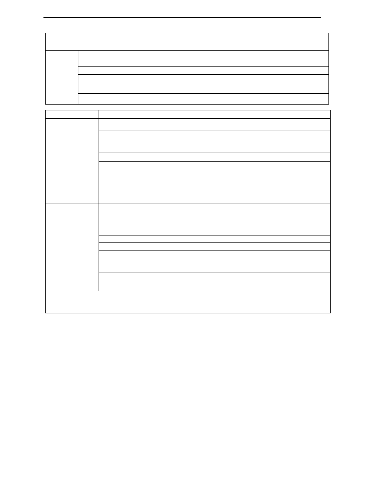
Operating temperature
Mode
Temperature
Cooling operation
Heating operation
Drying operation
Room temperature
17OC~32OC(62OF~90OF)
0OC~30OC(32OF~86OF)
17OC~32OC
(62OF~90OF)
Outdoor temperature
0OC~50OC
(32OF~122OF)
-15OC~24OC
(5OF~76OF)
0OC~50OC
(32OF~122OF)
(-15 OC 50C/ 5°F~122°F:
For the models with low
temperature cooling system)
NOTE:
1. Optimum performance will be achieved within these operating temperatures. If air
conditioner is used outside of the above conditions, certain safety protection features
might come into operation and cause the unit to function abnormally.
2. If the air conditioner operates in a room whose relative humidity is less than 80%
the surface of the air conditioner may attract condensation. Please sets the vertical
air flow louver to its maximum angle (vertically to the floor), and set HIGH fan mode.
Suggestion: For the unit adopts an Electric Heater, when the outside ambient temperature is below 0OC
(32OF), we strongly recommend you to keep the machine plugged in order to guarantee it running smoothly.
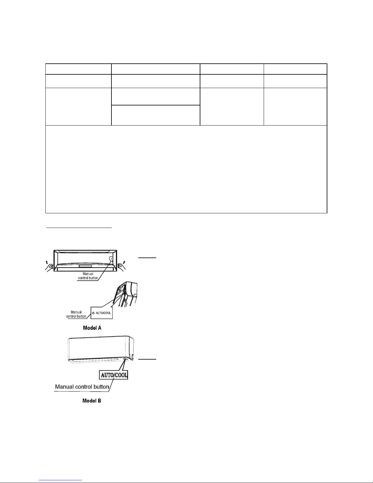
Manual operation
Manual operation can be used temporarily in case you can not find the remote controller or test running purpose
or maintenance necessary.
NOTE: The unit must be turned off before operating the manual control
button. If the unit is operational, continue pressing the manual control
button until the unit is off.
1) Open and lift the front panel up will see the manual control button
(see Model A) For some models, the manual control button is located at
the bottom of the unit(see Model B).
2) One press of the manual control button will lead to the forced
AUTO operation. If press the button twice with in five seconds, the unit
will operate under forced COOL operation.
3) Close the panel firmly to its original position.
NOTE: For DUCT and CEILING type, CASSETTE type, CEILING and
FLOOR type and FLOOR and STANDING type, please refer to the previous
pages to operate the Manual button.
12
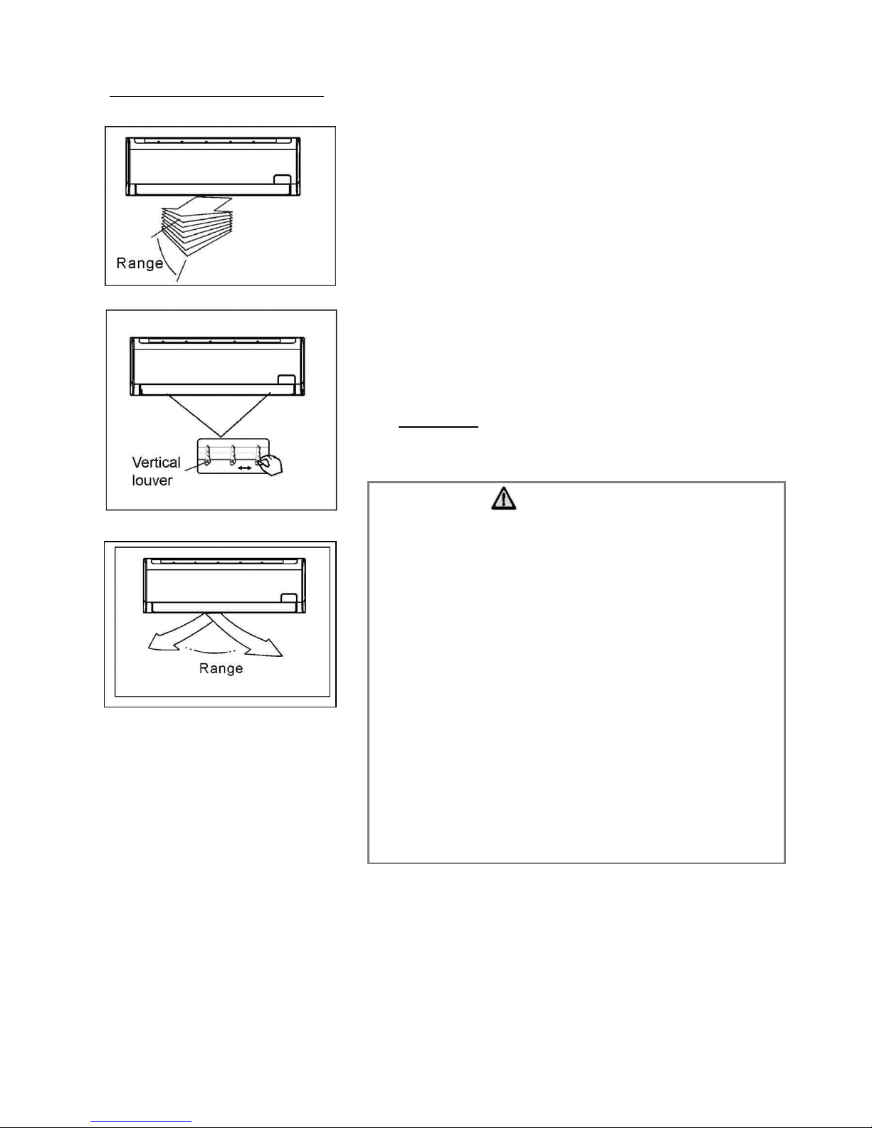
Airflow direction control
Adjust the air flow direction properly otherwise it might cause
discomfort or cause uneven room temperatures.
Adjust the horizontal/vertical louver using the remote
controller. For some models, the vertical louver can only be
adjusted manually.
To set the horizontal/vertical airflow direction
Perform this function while the unit is in operation.
Use the remote controller to adjust the air flow direction. The
vertical/horizontal louver changes6 degree in angle for each
press, or swing up and down automatically. Please refer to
the "REMOTE CONTROLLER OPERATION MANUAL , for
details.
For some models, the vertical louver can only be adjusted
manually. Move the deflector rod manually to adjust the air
flow in the direction you prefer.
IMPORTANT: Do not put your fingers into the panel of blower
and suction side. The high-speed fan inside may cause
danger.
• Do not operate the air conditioner for long periods with the
air flow direction set downward in cooling or dehumidifying
mode. Otherwise, condensation may occur on the surface of
the horizontal louver causing moisture to drop on to the floor
or on furnishings.
• Do not move the horizontal louver manually unless it is
necessary. Always use the remote controller.
• When the air conditioner is started immediately after it was
stopped, the horizontal louver might not move for
approximately 10 seconds.
• Open angle of the horizontal louver should not be set too
small, as COOLING or HEATING performance may be
impaired due to too restricted air flow area.
• Do not operate unit with horizontal louver in closed position.
• When the air conditioner is connected to power (initial
power), the horizontal louver may generate a sound for 10
seconds, this is a normal operation.
CAUTION
13
How the air conditioner works
AUTO operation
• When you set the air conditioner in AUTO mode, it will
automatically select cooling, heating (cooling /heating
models only), or fan only operation depending on what
temperature you have selected and the room
temperature.
• The air conditioner will control room temperature
automatically round the temperature point set by you.
• If the AUTO mode is uncomfortable, you can select
desired conditions manually.
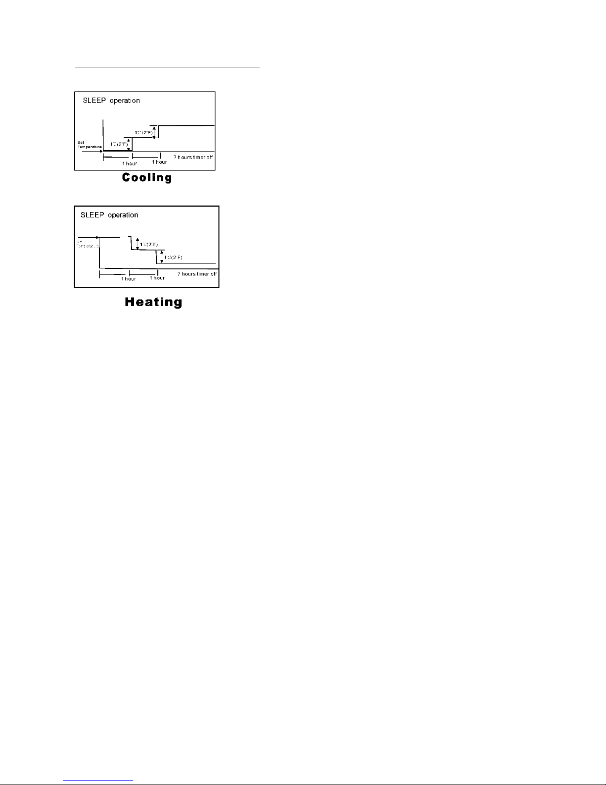
SLEEP operation
• When you push SLEEP button on remote controller
during cooling, heating(cooling only type without), or
AUTO operation , the air conditioner will automatically
increase(cooling)or decrease (heating) 1°C(2°F) per
hour.
• The set temperature will be steady2 hours later. And the
air conditioner will be timer off in 7 hours.
• The fan speed will be automatically controlled.
• This feature can maintain the most comfortable
temperature and save more energy for you.
DRYING operation
• The fan speed will be automatically controlled under dry
operation.
• During the dry operation, if the room temperature is
lower than 10OC(50oF), the compressor stops operation
and restarts until the room temperature is above
12OC(54oF).
14

Operation mode selection
While simultaneously operating two indoor units or more, make sure the operation modes will not conflict with
each other. The heat mode claims precedence over all other modes. If the intially started operates under heat
mode, the other units can operate under heat mode only. For example: If the unit intially started operates under
cool (or fan) mode, the other units can operate under any mode except heat. If one of the unit selects heat
mode, the other operating units will stop operation and diplay "P5"(For the units with display window only) or the
Auto and Operation indication light flash rapidly, the Defrost indication light turn off, the Timer indication light
remainon (For the units without display window),or the defrost and Alarm indication light ( if applicable)
illuminate ,the operation indication light flashes rapidly and the Timer indication light turns off(For the Floor and
standing type).
Optimal operation
To achieve optimal performance, please note the following:
• Adjust the air flow direction correctly so that it is not directed on people.
• Adjust the temperature to achieve the highest comfort level. Do not adjust the unit to excessive temperature
levels.
• Close doors and windows on COOL or HEAT modes, or performance may be reduced.
• Use TIMER ON button on the remote controller to select a time you want to start your air conditioner.
• Do not put any object near air inlet or air outlet, as the efficiency of the air conditioner may be reduced and the
air conditioner may stop running.
• Clean the air filter periodically, otherwise cooling or heating performance may be reduced.
• Do not operate unit with horizontal louvre in closed position.
Suggestion: For the unit adopts an Electric Heater, when the outside ambient temperature is below
0OC(32oF), we strongly recommend you to keep the machine plugged in order to guarantee it running
smoothly.
15

CARE AND MAINTENANCE
Care and maintenance
Cleaning the Grille, Case and Remote Controller
Turn the system off before cleaning. To clean, wipe
with a soft, dry cloth. Do not use bleach or abrasives.
NOTE: Supply power must be disconnectd before
cleaning the indoor unit.
■ WALL-MOUNTED TYPE
Cleaning the air filter
A clogged air filter reduces the cooling efficiency of
this unit. Please clean the filter once every 2 weeks.
1. Lift the indoor unit panel up to an angle until it stops
with a clicking sound.
2. Take hold of the handle of the air filter and lift it up
slightly to take it out from the filter holder, then pull it
downwards.
3. Remove the Active Carbon & Dust Filter from the
indoor unit.
• Clean the it once two weeks.
• Clean the it with a vacuum cleaner or water, then
dry it up in cool place.
CAUTIONS
A cloth dampened with cold water may be
used on the indoor unit if it is very dirty.
Then wipe it with a dry cloth.
Do not use a chemically treated cloth or
duster to clean the unit.
Do not use benzine, thinner, polishing
powder, or similar solvents for cleaning.
These may cause the plastic surface to
crack or deform.
Never use water hotter than 40°C(104°F)
to clean the front panel, it could cause
deformation of discoloration.
16
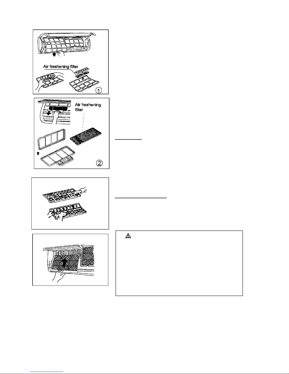
4. Remove the Air Freshening Filter(Optional filter:
Plasma Dust collector/Silver Ion filter /Bio filter/ Vitamin C
filter) from its support frame. (The installation and
removing method of the air freshening filter is different
depending on the models, see the pictures marked 1 and
2 on the left.
• Clean the air freshening filter at least once a month,
and replace it every 4-5 months.
• Clean it with vacuum cleaner, then dry it in cool
place.
5. Install the air freshening filter back into position.
6. Insert the upper portion of air filter back into the unit
taking care that the left and right edges line up correctly
and place filter into position.
Maintenance
If you plan to idle the unit fora long time, perform the following:
(1) Operate the fan for about half a day to dry the
Inside of the unit.
(2) Stop the air conditioner and disconnect power.
Remove the batteries from the remote controller.
(3) The outdoor unit requires periodic maintenance
and cleaning. Do not attempt to do this yourself.
Contact your dealer or servicer.
Checks before operation
• Check that the wiring is not broken off or disconnected.
• Check that the air filter is installed.
• Check if the air outlet or inlet is blocked after the air
conditioner has not been used for a longtime.
CAUTION
Do not touch the metal parts of the unit when
removing the filter. Injuries can occur when
handling sharp metal edges.
Do not use water to clean inside the air conditioner.
Exposure to water can destroy the insulation,
leading to possible electric shock.
When cleaning the unit, first make sure that the
power and circuit breaker are turned off.
17

OPERATION TIPS
Maintenance
If you plan to idle the unit for a long time, perform the following:
1. Clean the indoor unit and air filter.
2. Select FAN only mode, let the indoor fan run for a while to dry the inside of the unit.
3. Disconnect the power supply and remove battery from the remote control.
4. Check components of the outdoor unit periodically. Contact a local dealer or a customer service centre if
the unit requires servicing.
Note: Before you clean the air conditioner, be sure to switch the unit off and disconnect the power supply plug.
When the air conditioner is to be used again:
• Use a dry cloth to wipe off the dust accumulated on rear air intake grille, in order to avoid the dust blowing
out from the indoor unit.
• Check that the wiring is not broken off or disconnected.
• Check that the air filter is installed.
• Check if the air outlet or inlet is blocked after the air conditioner has not been used for a long time.
Operation Tips
The following events may occur during normal operation.
1. Protection of the air conditioner.
Compressor protection
• The compressor can't restart for 3 minutes after it stops.
Anti-cold air (Cooling and heating models only)
• The unit is designed not to blow cold air on HEAT mode, when the indoor heat exchanger is in one of
the following three situations and the set temperature has not been reached.
A) When heating has just starting.
B) Defrosting.
C) Low temperature heating.
• The indoor or outdoor fan stop running when defrosting (Cooling and heating models only).
Defrosting (Cooling and heating models only)
• Frost may be generated on the outdoor unit during heat cycle when outdoor temperature is low and
humidity is high resulting in lower heating efficiency of the air conditioner.
• During this condition air conditioner will stop heating operation and start defrosting automatically.
• The time to defrost may vary from 4 to 10 minutes according to the outdoor temperature and the amount
of frost buildup on the outdoor unit.
2. A white mist coming out from the indoor unit
• A white mist may generate due to a large temperature difference between air inlet and air outlet on
COOL mode in an indoor environment that has a high relative humidity.
• A white mist may generate due to moisture generated from defrosting process when the air conditioner
restarts in HEAT mode operation after defrosting.
3. Low noise of the air conditioner
• You may hear a low hissing sound when the compressor is running or has just stopped running.
This sound is the sound of the refrigerant flowing or coming to a stop.
• You can also hear a low "squeak" sound when the compressor is running or has just stopped running.
This is caused by heat expansion and cold contraction of the plastic parts in the unit when the
temperature is changing.
• A noise may be heard due to louver restoring to its original position when power is first turned on.
18

4. Dust is blown out from the indoor unit.
This is a normal condition when the air conditioner has not been used for a long time or during first use of the
unit.
5. A peculiar smell comes out from the indoor unit.
This is caused by the indoor unit giving off smells permeated from building material, from furniture, or smoke.
6. The air conditioner turns to FAN only mode from COOL or HEAT (For cooling and heating models
only) mode.
When indoor temperature reaches the temperature setting on air conditioner, the compressor will stop
automatically, and the air conditioner turns to FAN only mode. The compressor will start again when the
indoor temperature rises on COOL mode or falls on HEAT mode (For cooling and heating models only) to the
set point.
7. Dripping water may generate on the surface of the indoor unit when cooling ina high relatively humidity
(relative humidity higher than 80%). Adjust the horizontal louver to the maximum air outlet position and select
HIGH fan speed.
8. Heating mode (For cooling and heating models only)
The air conditioner draws in heat from the outdoor unit and releases it via the indoor unit during heating
operation. When the outdoor temperature falls, heat drawn in by the air conditioner decreases accordingly. At
the same time, heat loading of the air conditioner increases due to larger difference between indoor and
outdoor temperature. If a comfortable temperature can't be achieved by the air conditioner, we suggest you
use a supplementary heating device.
9. Auto-restart function
Power failure during operation will stop the unit completely.
For the unit without Auto-restart feature, when the power restores, the OPERATION indicator on the indoor
unit starts flashing. To restart the operation, push the ON/OFF button the remote controller. For the unit with
Auto-restart feature, when the power restores, the unit restarts automatically with all the previous settings
preserved by the memory function.
10. Lightning or a car wireless telephone operating near by may cause the unit to malfunction.
Disconnect the unit with power and then re-connect the unit with power again. Push the ON/OFF button on
the remote controller to restart operation.
19
Stop the air conditioner immediately if one of the following faults occur. Disconnect the
power and contact the nearest customer service center.
If the E( 0,1 ........) or P( 0, 1 ....... ) code appears on the LED(LCD)window, disconnect the
power and contact the service people.
Trouble
Fuse blows frequently or circuit breaker trips frequently.
Other objects or water penetrate the air conditioner.
The remote controller won't work or works abnormally.
Other abnormal situations.
Malfunctions
Cause
What should be done?
Unit does not
start
Power cut
Wait for power to be restored.
Unit may have become unplugged.
Check that plug is securely in wall
receptacle.
Fuse may have blown.
Replace the fuse.
Battery in Remote controller may have
been exhausted.
Replace the battery.
The time you have set with timer is
incorrect.
Wait or cancel timer setting.
Unit not cooling
or heating
(Cooling/ heating
models only)
room very well
while air flowing
out from the air
conditioner
Inappropriate temperature
setting.
Set temperature correctly. For detailed
method please refer to "Remote controller
instruction" section.
Air filter is blocked.
Clean the air filter.
Doors or Windows are open.
Close the doors or windows.
Air inlet or outlet of indoor or outdoor unit
has been blocked.
Clear obstructions away first, then restart the
unit.
Compressor3minutes protection has been
activated.
Wait.
If the trouble has not been corrected, please contact a local dealer or the nearest customer
service center. Be sure to inform them of the detailed malfunctions and unit model.
Notes: Do not attempt to repair the unit yourself.
Always consult an authorised service provider.
TROUBLESHOOTING TIPS
20

INSTALATION
INSTRUCTIONS
CONTENTS
SAFETY PRECAUTIONS
Warning ............................................................................................................................................................... 2
Caution ................................................................................................................................................................. 2
INSTALLATION INSTRUCTIONS
Selecting installation place .................................................................................................................................... 3
Wall-mounted type ................................................................................................................................................ 3
Accessories ..........................................................................................................................................................4
Four-way cassette type .........................................................................................................................................5
Outdoor unit installation ........................................................................................................................................9
REFRIGERANT PIPE CONNECTION
Refrigerant pipe connection ..............................................................................................................................10
ELECTRICAL WORK
Electrical work ................................................................................................................................................... 11
AIRPURGING
Air purging with vacuum pump ......................................................................................................................... 16
Safety and leakage check ................................................................................................................................. 17
TESTRUNNING
Test running ...................................................................................................................................................... 18
Read This Manual
Inside you will find many helpful hints on how to install and test the air conditioner properly.
All the illustrations and specifications in the manual are subject to change without prior notice for product
improvement. The actual shape should prevail.
CAUTION
• Contact an authorised service technician for repair or maintenance of this unit.
• The appliance shall be installed in accordance with national wiring regulations.
• This appliance is not intended for use by persons (including children) with reduced physical, sensory or
mental capabilities, or lack of experience and knowledge, unless they have been given supervision or
instruction concerning use of the appliance by a person responsible for their safety.
• Young children should be supervised to ensure that they do not play with the air conditioner.
• Do not operate your air conditioner in a wet room such as a bathroom or laundry room.
• Installation work must be performed in accordance with the national wiring standards by authorized
personnel only.
SAFETY PRECAUTIONS
• Read the follow SAFETY PRECAUTIONS carefully before installation.
• Electrical work must be installed by a licensed electrician. Be sure to use the correct rating of the power plug
and main circuit for the model to be installed.
• Incorrect installation due to ignoring of the instruction will cause harm or damage.
■ The seriousness is classified by the following indications.
WARNING
This symbol indicates the possibility of death or serious injury.
CAUTION
This symbol indicates the possibility of injury or damage to property.
The items to be followed are classified by the symbols:
WARNING
1) Engage dealer or specialist for installation. If installation done by the user is defective, it will
cause water leakage, electrical shock or fire.
2) Install according to this installation instructions strictly. If installation is defective, it
will cause water leakage, electrical shock or fire.
3) Use the attached accessories parts and specified parts for installation. otherwise, it will cause
the set to fall, water leakage, electrical shock or fire.
4) Install at a strong and firm location which is able to withstand the set's weight. If the strength is
not enough or installation is not properly done, the set will drop and cause injury.
5) For electrical work, follow the local national wiring standard, regulation and this installation
instructions. An independent circuit and single outlet must be used. If electrical circuit capacity
is not enough or defect found in electrical work, it will cause electrical shock or fire.
6) Use the specified cable and connect tightly and clamp the cable so that no external force will
be acted on the terminal. If connection or fixing is not perfect, it will cause heat-up or fire at the
connection.
7) Wiring routing must be properly arranged so that control board cover is fixed properly. If control
board cover is not fixed perfectly, it will cause heat-up at connection point of terminal, fire or
electrical shock.
8) When carrying out piping connection, take care not to let air substances other than the
specified
refrigerant go into refrigeration cycle. Otherwise, it will cause lower capacity, abnormal high
pressure in the refrigeration cycle, explosion and injury.
9) Do not modify the length of the power supply cord or use of extension cord, and do not share
the single outlet with other electrical appliances. Otherwise, it will cause fire or electrical shock.
CAUTION
1) This equipment must be earthed and installed with earth leakage current breaker. It may cause
electrical shock if grounding is not perfect.
2) Do not install the unit at place where leakage of flammable gas may occur. In case gas leaks
and accumulates at surrounding of the unit, it may cause fire.
3) Carry out drainage piping as mentioned in installation instructions. If drainage is not perfect,
water may enter the room and damage the furniture.
4) The appliance shall be installed in accordance with national wiring regulations.
5) Do not operate your air conditioner in a wet room such as a bathroom or laundry room.
6) An all-pole disconnection device which has at least 3mm clearances in all poles , and have a leakage current
that may exceed 10mA, the residual current device (RCD) having a rated residual operating current not
exceeding 30mA, and disconnection must be incorporated in the fixed wiring
in accordance with the wiring rules.
Symbol with background white denotes item that is PROHIBITED from
doing.
2
1. Wall-mounted type
Selecting installation place
Read co mp l e tely, th en f o llow step by st ep .
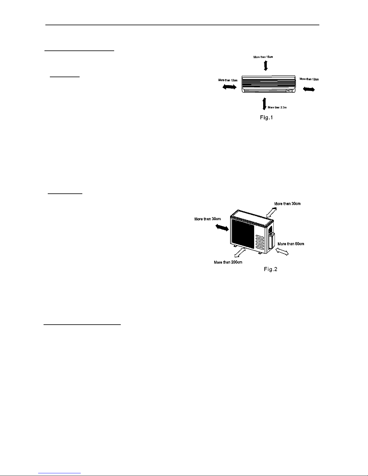
Indoor unit
• Do not expose the indoor unit to heat or steam.
• Select a place where there are no obstacles in front or
around the unit.
• Make sure that condensation drainage can be conveniently
routed away.
• Do not install near a doorway.
• Ensure that the space on the left and right of the unit is more
than 12cm.
• Use a stud finder to locate studs to prevent unnecessary damage to the wall.
• The indoor unit should be installed on the wall at a height of 2.3 metres or more from the floor.
• The indoor unit should be installed allowing a minimum clearance of 15cm from the ceiling.
• Any variations in pipe length will/may require adjustment to refrigerant charge.
• There should not be any direct sunlight. Otherwise, the sun will fade the plastic cabinet and affect its
appearance. If unavoidable, sunlight prevention should be taken into consideration.
Outdoor unit
• If an awning is built over the outdoor unit to
prevent direct sunlight or rain exposure, make sure
that heat radiation from the condenser is not
restricted.
• Ensure that the clearance around the back of the
unit is more than 30cm and left side is more than
30cm. The front of the unit should have more than
200cm of clearance and the connection side (right
side) should have more than 60cm of clearance.
• Do not place animals and plants in the path of the
air inlet or outlet.
• Take the air conditioner weight into account and select a place where noise and vibration will not be an
issue.
• Select a place so that the warm air and noise from the air conditioner do not disturb neighbors.
Rooftop installation:
• If the outdoor unit is installed on a roof structure, be sure to level the unit.
• Ensure the roof structure and anchoring method are adequate for the unit location.
• Consult local codes regarding rooftop mounting.
• If the outdoor unit is installed on roof structures or external walls, this may result in excessive noise and
vibration, and may also be classed as a non serviceable installation.
INSTALATION INSTRUCTIONS
3
Tools needed forinstallation:
LeveL gauge Screwdriver
Electric drill, Hole core drill ( Φ 65mm)
Flaring tool set
Specified torque wrenches: 1.8kgf.m, 4.2kgf.m,
5.5kgf.m, 6.6kgf.m (different depending on model No.)
Spanner (half union)
Hexagonal wrench (4mm)
Gas-leak detector
Vacuum pump
Gauge manifold
Users manual
Thermometer
Multimeter
Pipe cutter
Measuring tape
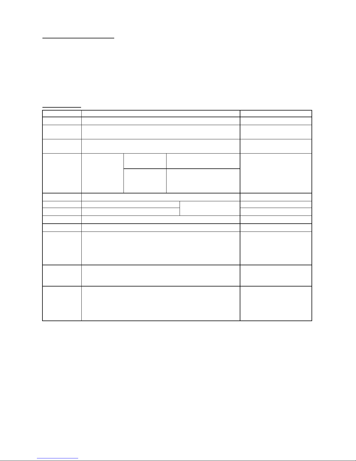
Accessories
Number
Name of Accessories
Q’ ty/one unit
1
Installation Plate
1
2
Plastic Expansion Sheath
5-8
(depending on models)
3
Self-tapping Screw AST3.9X25
5-8
(depending on models)
4
Connecting
pipe
Assembly
Liquid side
Φ 6.35
Φ 9.52
Parts you must purchase
Consult the technician
For the proper size.
Gas side
Φ 9.52
Φ 12.7
Φ 15.9
5
Remote controller
1
6
Self-tapping Screw B ST2.9X10
Optional parts
2
7
Remote controller holder
1
8
Seal (for cooling & heating models only)
1
9
Drain Joint (for cooling& heating models only)
1
10
Transfer connector (Packed with the indoor unit)
(NOTE: Pipe size differ from appliance to appliance. To meet
different pipe size requirement, sometimes the pipe
connections need the transfer connector to install on the
outdoor unit.)
3-4
(on some models)
11
Magnetic ring
(Hitch it on the connective cable between indoor unit and
outdoor unit after installation.)
Optional part
(one piece/one cable)
12
Cord protection rubber ring
(If the cord clamp can not fasten the cord for the small size of
the cord, please use the cord protection rubber ring (supplied
with accessories) to wrap on the cord, then fix it with the cord
clamp.)
1
(on some models)
Note: Except the above parts provided, the other parts needed during installation you must purchase.
4
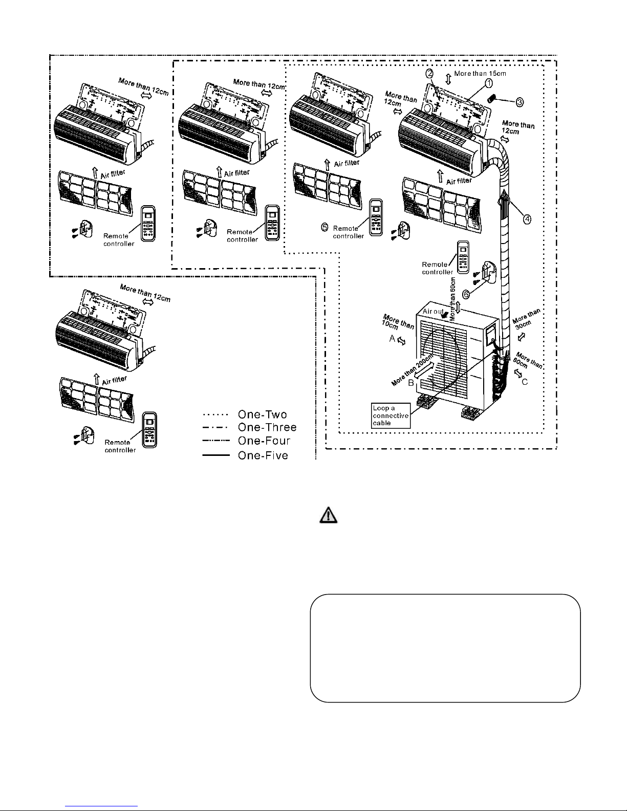
Fig.3
CAUTIONS
• This illustration is for explanation purposes only.
The actual shape of your air conditioner may be slightly
different.
• Copper lines must be insulated independently
CAUTION
• Use a stud finder to locate studs to prevent
unnecessary damage to the wall.
• A minimum pipe run of 3 metres is required to
minimise vibration & excessive noise.
• Two of the A, B and C directions should be free from
obstructions.
5
I
Indoor unit installation(wall-mounted type)
1. Fit the installation plate horizontally on structural parts
of the wall with spaces around the installation plate.
2. If the wall is made of brick, concrete or the like, drill
five or eight 5mm diameter holes in the wall. Insert
Clip anchor for appropriate mounting screws.
3. Fit the installation plate on the wall with five or eight
type "A" screws.
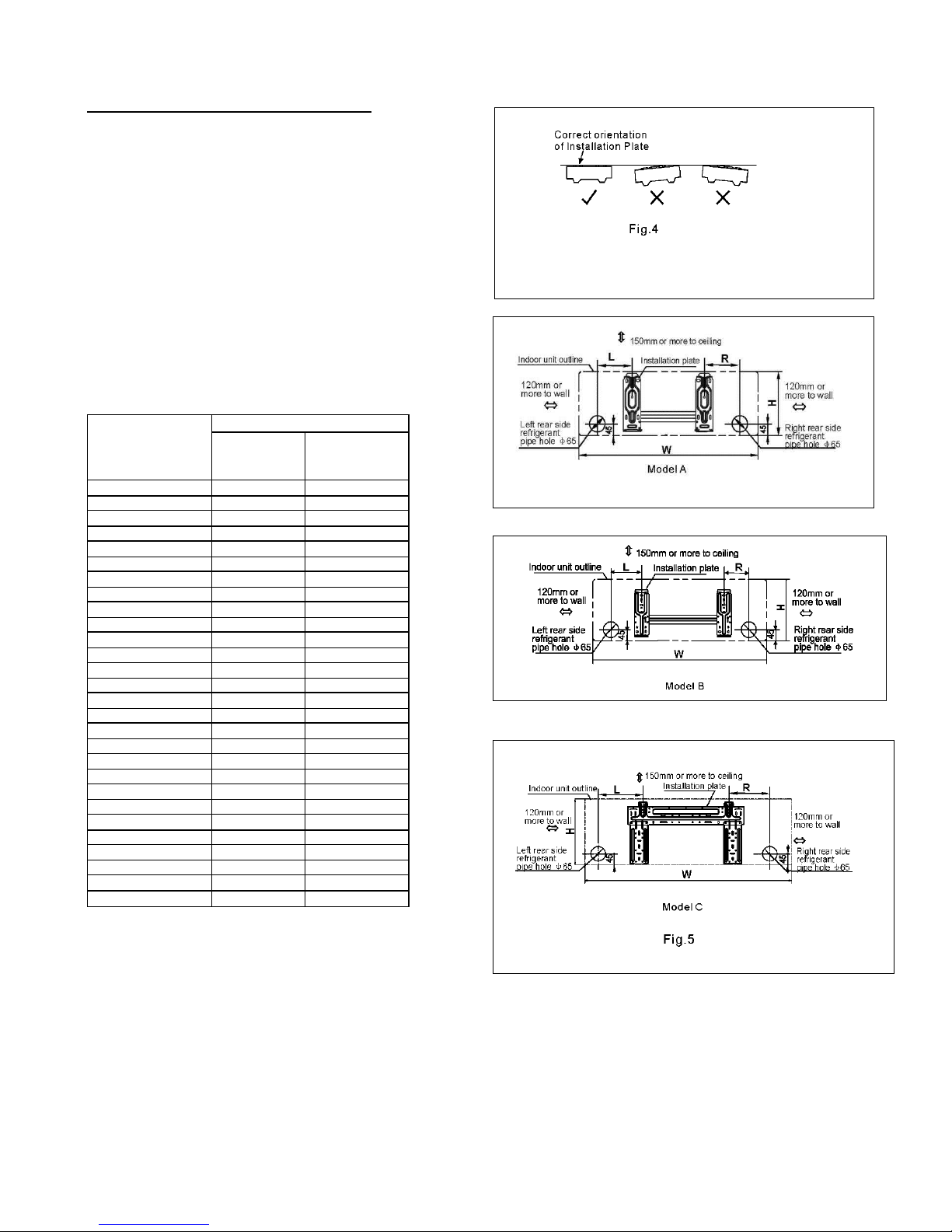
Note:
Fit the Installation Plate and drill holes in the wall
according to the wall structure and indoor unit
dimensions and the corresponding mounting points on
the installation plate. The Installation Plate may be
slightly different according to the different models of
indoor unit. See Fig.5 for example. (Dimensions are in
"mm" unless otherwise stated.)
Indoor unit
dimension
mm(W x H)
Mountingdimensions
L(Left)
R(Right)
710x250
100
160
790x265
100
150
920x292
150
185
1080x330
70
105
790x275
100
85
930x275
150
205
998x322
100
120
680x255
170
92
770x255
170
95
905x275
80
100
750x280
180
110
835x280
140
110
990x315
260
135
1186x343
275
275
900x290
83
170
1045x305
100
170
715x250
85
88
800x275
100
95
940x275
110
100
1045x315
293
163
795x270
150
160
845x286
150
186
995x295
150
200
1084x320
150
140
850x275
100
130
900x285
150
90
1015x298
150
200
850x290
100
115
6
2. Drill a hole in the wall
1. Determine hole positions according to the
diagram detailed in Fig.5. Drill one (1) hole ( Φ
65mm) slanting slightly to outdoor side.
2. Always use wall hole conduit when drilling metal
grid, metal plate or the like.
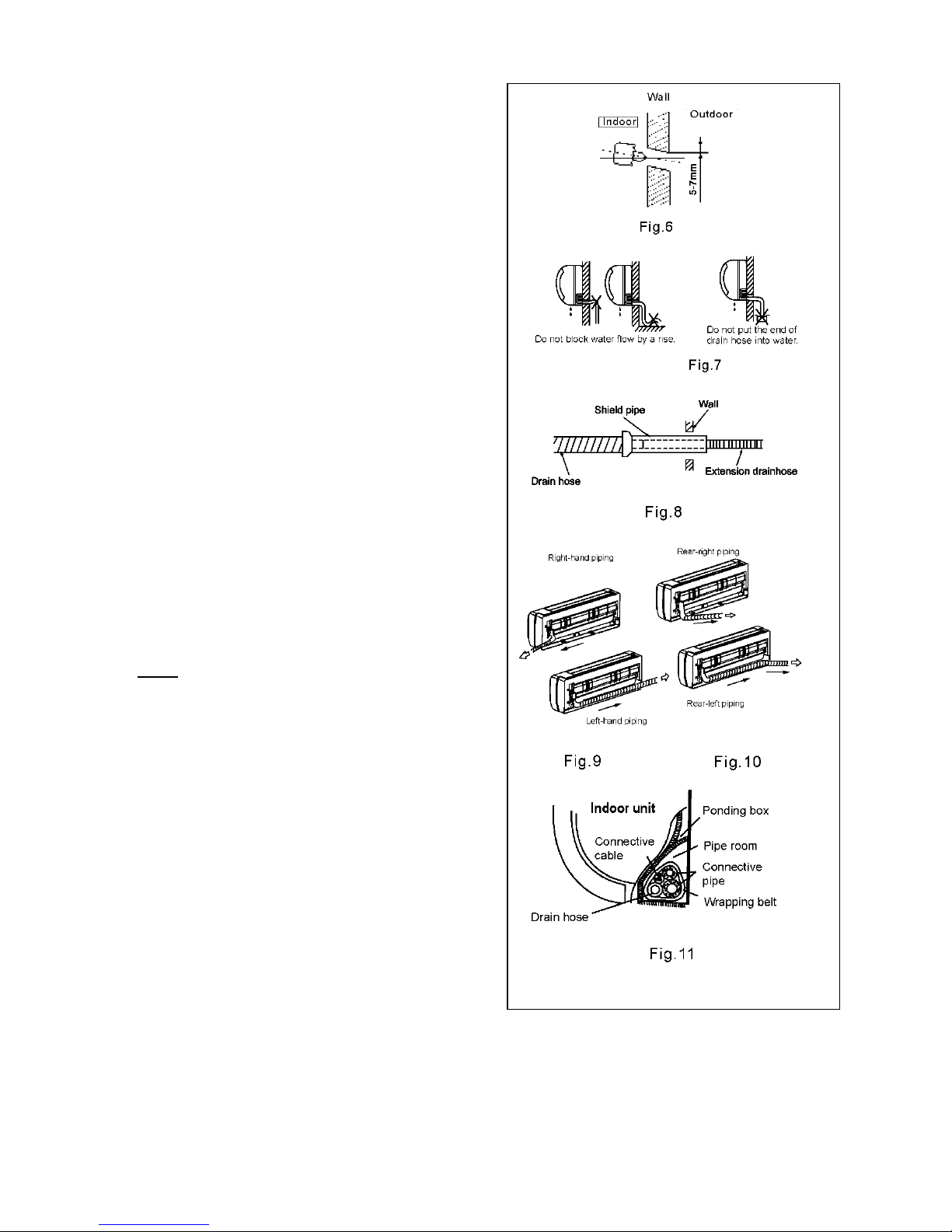
3. Connective Pipe and Drainage
Installation Drainage
1. Run the drain hose sloping downward. Do not
install the drain hose as illustrated in Fig.7.
2. When connecting extension drain hose, insulate
the connecting part of extension drain hose with
a shield pipe, do not let the drain hose slack.
Connective pipe installation
1. For the left-hand and right-hand piping, remove
the pipe cover from the side panel.
2. For the rear-right-hand and rear-left-hand piping,
install the piping as shown in Fig. 10.
3. Fix the end of the connective pipe.
(Refer to Tightening Connection in
REFRIGERANT PIPING CONNECTION)
4. Piping and wrapping
Bundle the tubing, connecting cable, and drain
hose with tape securely, evenly as shown in
Fig.11.
• Because the condensed water from rear of the
indoor unit is gathered in ponding box and is
piped out of room. Do not put anything else in the
box.
CAUTION
• Connect the indoor unit first, then the outdoor
unit.
• Do not allow the piping to let out from the back of
the indoor unit.
• Be careful not to let the drain hose slack.
• Heat insulated both of the auxiliary piping.
• Be sure that the drain hose is located at the
lowest side of the bundle. Locating at the upper
side can cause drain pan to overflow inside the
unit.
• Never intercross nor inter twist the power wire
with any other wiring.
• Run the drain hose sloped downward to drain out
the condensed water smoothly.
7
 Loading...