

Vivax ACP-09CH25AERO, ACP-12CH35AERO, ACP-18CH50AERO, ACP-24CH70AERO, ACP-12CH35AEXO Service Manual
EN
Service manual 2016
ACP-09CH25AERO ACP-18CH50AERO
ACP-12CH35AERO ACP-24CH70AERO
ACP-12CH35AEXO

CONTENTS
1. Precaution .................................................................................................................................................... 1
1.1 Safety Precaution .......................................................................................................................... 1
1.2 Warning ......................................................................................................................................... 1
2. Function ........................................................................................................................................................ 5
3. Dimension .................................................................................................................................................... 6
3.1 Indoor Units ................................................................................................................................... 6
3.2 Outdoor Units ................................................................................................................................ 8
4. Refrigerant Cycle Diagram ......................................................................................................................... 9
5. Installation details ..................................................................................................................................... 10
5.1 Wrench torque sheet for installation ........................................................................................... 10
5.2 Connecting the cables ................................................................................................................ 10
5.3 Pipe length and the elevation ...................................................................................................... 11
5.4 Installation for the first time ......................................................................................................... 12
5.5 Adding the refrigera nt after running the sy stem for many years ................................................ 16
5.6 Re-installation while the indoor unit need to be repaired ........................................................... 17
5.7 Re-installation while the outdoor unit need to be repaired ......................................................... 19
6. Operation characteristics ......................................................................................................................... 22
7. Electronic function .................................................................................................................................... 23
7.1 Abbreviation ................................................................................................................................ 23
7.2 Display function ........................................................................................................................... 23
7.3 Main Protection ........................................................................................................................... 24
7.4 Operation Modes and Functions ................................................................................................. 25
8. Troubleshooting ......................................................................................................................................... 30
8.1 Indoor unit error display .............................................................................................................. 30
8.2 Diagnosis and Solution ............................................................................................................... 31

1
1. Precaution
1.1 Safety Precaution
To prevent injury to the user or other people and property damage, the following
instructions must be followed.
Incorrect operation due to ignoring instructio n will cause harm or damage.
Before service unit, be sure to read this service manual at first.
1.2 Warning
¾ Installation
Do not use a defective or underrated ci rcuit breaker. Use this appliance on a dedicated
circuit.
There is risk of fire or electric shock.
For electrical work, contact the dealer, seller, a qualified electrician, or an Authorized
service center .
Do not disassemble or repair the product, there is risk of fire or electric shock.
Always ground the product.
There is risk of fire or electric shock.
Install the panel and the cover of control box securely.
There is risk of fire of electric shock.
Always install a dedicated circuit and breaker.
Improper wiring or installation may cause fore or electric shoc k.
Use the correctly rated breaker of fus e.
There is risk of fire or electric shock.
Do not modify or extend the power cable.
There is risk of fire or electric shock.
Do not install, remove, or reinstall the unit by yourself(customer).
There is risk of fire, electric shock, explosion, or injury.
Be caution when unpa cking and installing the product.
Sharp edges could cause injury, be especially careful of the case edges and the fins on the
condenser and evaporator.
For installation, always contact the dealer or an Authorized service center.
There is risk of fire, electric shock, explosion, or injury.
Do not install the product on a defective installation stand.
It may cause injury, accident, or damage to the product.
Be sure the installation area does not deteriorate with age.
If the base collapses, the air conditioner could fall with it, causing propert y damage, product failure,
and personal injury.
Do not let the air conditioner run for a long time when the humidity is very high and a
door or a window is left open.
Moisture may condense and wet or damage furn iture.
Take care to ensure that power cable could not be p ull ed out or damaged during
operation.

2
There is risk of fire or electric shock.
Do not place anything on t he power cable.
There is risk of fire or electric shock.
Do not plug or unplug the power supply plug during operation.
There is risk of fire or electric shock.
Do not touch (operation) the product with wet hands.
There is risk of fire or electric shock.
Do not place a heater or other appliance near the power cable.
There is risk of fire and electric shock.
Do not allow wat e r to run into electric parts.
It may cause fire, failure of the product, or electric shock.
Do not store or use flammable gas or comb ustible near the product.
There is risk of fire or failure of product.
Do not use the product in a tightly closed space for a long time.
Oxygen deficiency could occur.
When flammable gas leaks, turn off the gas and open a window for ventilation before
turn the product on.
Do not use the telephone or turn switches on or of f.
There is risk of explosion or fire.
If strange sounds, or small or smoke comes from product. Turn the breaker off or
disconnect the power supply cable.
There is risk of electric shock or fire.
Stop operation and close the window in storm or hurricane. If possible, remove the
product from the window before the hurricane arrives.
There is risk of property damage, failure of product, or electric shoc k.
Do not open the inlet grill of the product during operation. (Do not touch the
electrostatic filter, if the unit is so equipped.)
There is risk of physical injury, electric shock, or product fa il ure.
When the product is soaked (flooded or submerged), contact an Authorized service
center.
There is risk of fire or electric shock.
Be caution that water could n ot enter the product.
There is risk of fire, electric shock, or product damage.
Ventilate the product from time to time when operating it toget her with a stove, etc.
There is risk of fire or electric shock.
Turn the main power off when cleani ng or maintaining the product.
There is risk of electric shock.
When the product is not be used f or a long time, disconnect the power supply plug or
turn off the breaker.
There is risk of product damage or failure, or unintended operation.
Take care to ensure that nobody could step on or fall onto the outdoor unit.
This could result in personal injury and product damage.
¾ CAUTION
Always check for gas (refrigerant) leakage after installati on or repair of product.
Low refrigerant levels may cause failure of pro duct.

3
Install the drain hose to ensure that water is drained away properly.
A bad connection may cause water leakage.
Keep level even when installing the prod uct.
It can avoid vibration of water leakage.
Do not install the product where the noise or hot air from the outdoor unit could
damage the neighborhoods.
It may cause a problem for your neighbors.
Use two or more people to li ft and transport the product.
Avoid personal in jury.
Do not install the product where it will be exposed to sea wind (salt spray) directly.
It may cause corrosion on the product. Corrosion, particularly on the condenser and evaporator
fins, could cause product malfunction or inefficient operation.
¾ Operational
Do not expose the skin directly to cool air for long peri od s of time . (Do not sit in the
draft).
This could harm to your health.
Do not use the product for special purposes, such as preserving foods, works of art,
etc. It is a consumer air conditioner, not a precision refrigerant system.
There is risk of damage or loss o f prop erty.
Do not block the inlet or outlet of air flow.
It may cause product failure.
Use a soft cloth to clean. Do not use harsh detergents, solvents, etc.
There is risk of fire, electric shock, or damage to the plastic parts of the product.
Do not touch the metal parts of the product when removing the air filter. They are very
sharp.
There is risk of personal injury.
Do not step on or put anything on the product. (outdoor units)
There is risk of personal injury and f ailure of product.
Always insert the filter securely. Clean the filter every two weeks or more often if
necessary.
A dirty filter reduces the efficiency of the air conditioner and could cause product malfun ction or
damage.
Do not insert hands or other object throug h air inlet or outlet whil e the product is
operated.
There are sharp and moving parts that could cause personal injury.
Do not drink the water drained from the product.
It is not sanitary could cause serious health issues.
Use a firm stool or ladder when cleaning or maintaining the product.
Be careful and avoid personal injury .
Replace the all batteries in the remote control with new ones of the same type. Do not
mix old and mew batteries or differe nt types of batteries.
There is risk of fire or explosion.
Do not recharge or disassem ble the batteries. Do not dispose of batteries in a fire.
They may burn of explode.
If the liquid from the batteries gets onto your skin or clothes, wash it well with clean

4
water. Do not use the remote of the batteries have leaked.
The chemical in batteries could cause burns or other health hazards
5
2. Function
Model Names of Indoor/Outdoor Units
Series
Capacity
Indoor units Outdoor units
On-Off
9k
ACP-09CH25AERO/I
ACP-09CH25AERO/O
11k
ACP-12CH35AERO/I
ACP-12CH35AERO/O
ACP-12CH35AEXO/I
ACP-12CH35AEXO/O
18k
ACP-18CH50AERO/I
ACP-18CH50AERO/O
24k
ACP-24CH70AERO/I
ACP-24CH70AERO/O
6
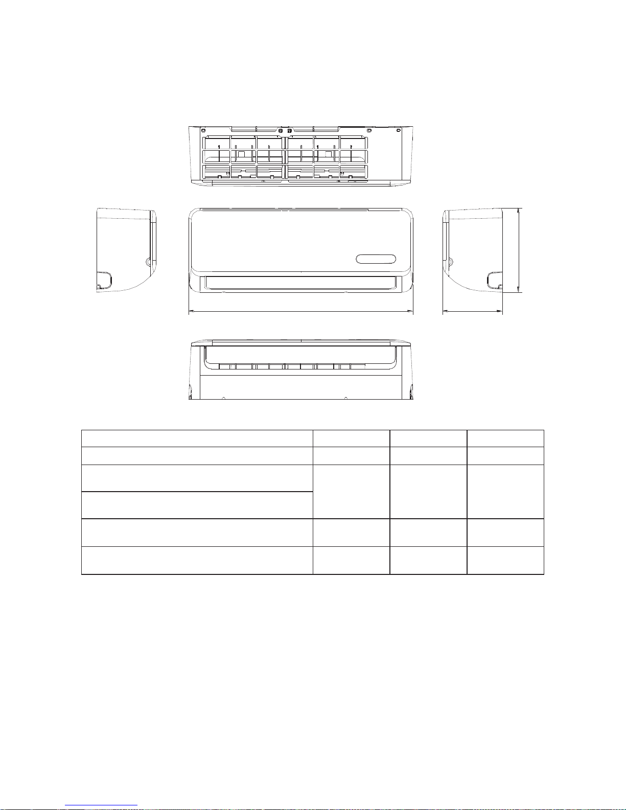
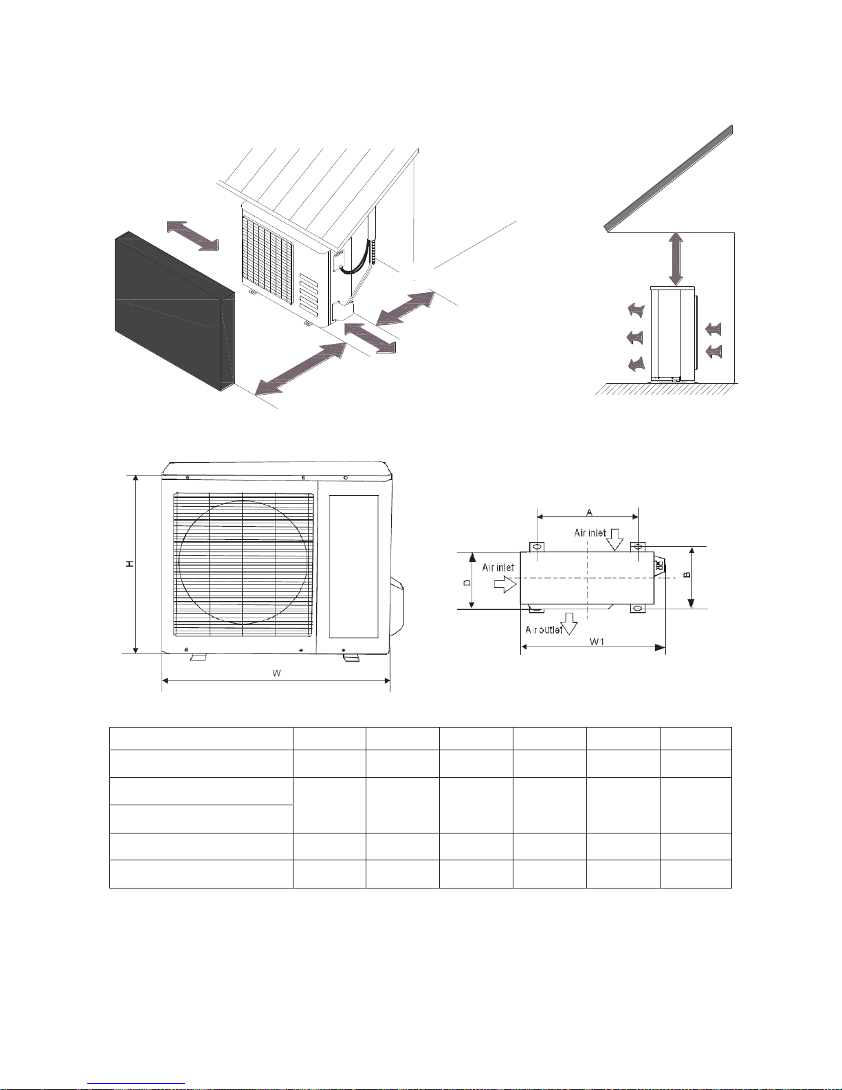
3. Dimension
3.1 Indoor Units
W
D
H
Model
W D H
ACP-09CH25AERO/I
680
178
255
ACP-12CH35AERO/I
770 188 255
ACP-12CH35AEXO/I
ACP-18CH50AERO/I 905 198 275
ACP-24CH70AERO/I 1030 218 315
7
L
R
H
Model
L(mm)
R(mm)
H(mm)
Dimension of
installation hole(mm)
ACP-09CH25AERO/I
170
92
45
65
ACP-12CH35AERO/I
170
95
45
ACP-12CH35AEXO/I
ACP-18CH50AERO/I
80
100
45
Model
L(mm)
R(mm)
H(mm)
Dimension of insta llation
hole(mm)
ACP-24CH70AERO/I 2
93
163
45
65
L
R
8
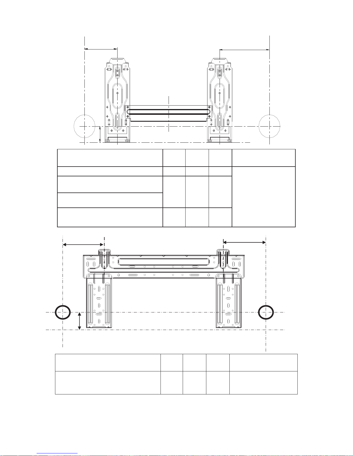
3.2 Outdoor Units
More than 30cm
More than 60cm
More than 200cm
More than 30cm
More than 60cm
(Service space
Fence or
obstacles
Model
W H D
W1 A B
ACP-09CH25AERO/O
685
260
430
742
460
276
ACP-12CH35AERO/O
700
240
540
757
458
250
ACP-12CH35AEXO/O
ACP-18CH50AERO/O
780
250
540
843
549
276
ACP-24CH70AERO/O
845
320
700
908
560
335
9
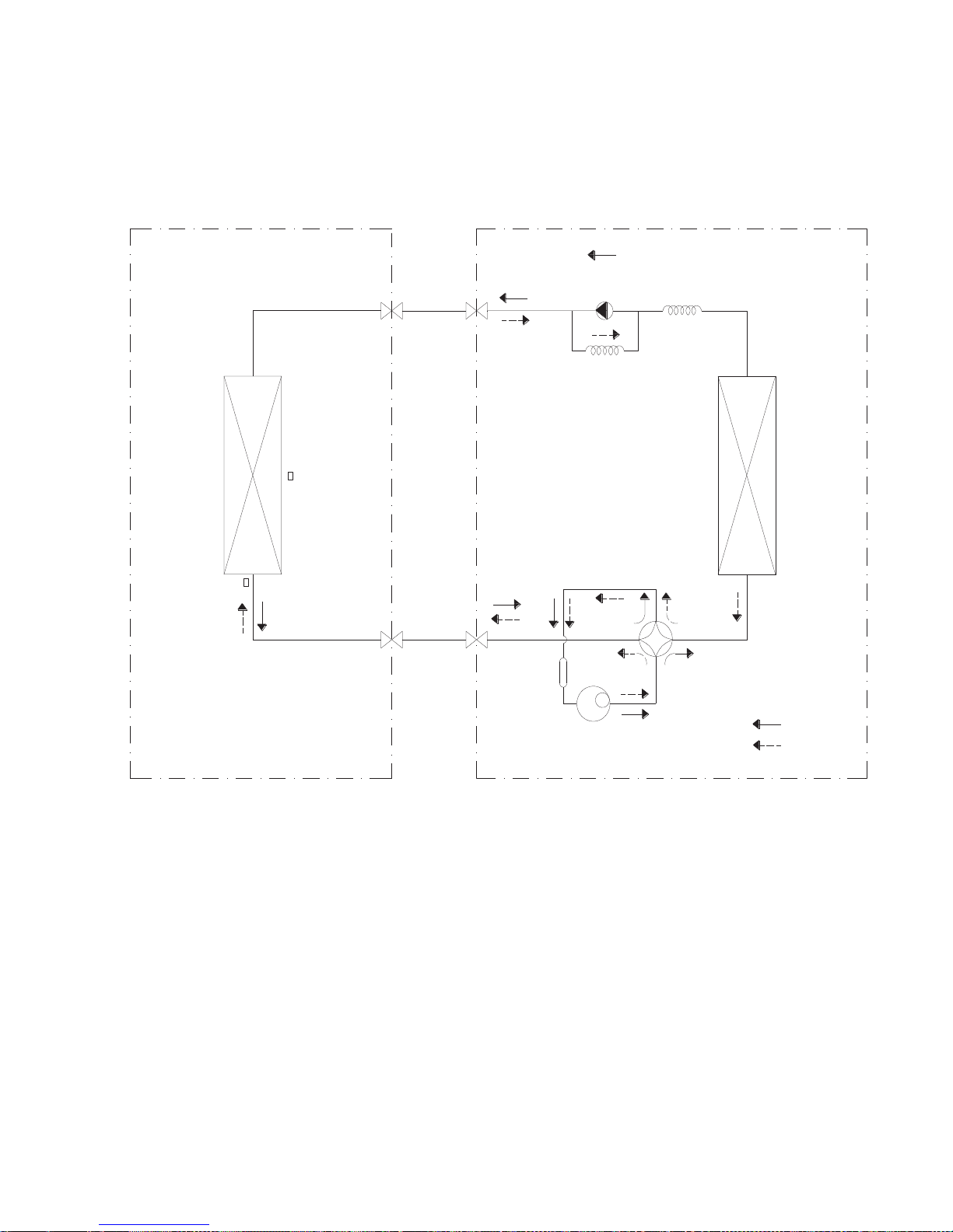
4. Refrigerant Cycle Diagram
For heat pump models:
LIQUID SIDE
GAS SIDE
HEAT
EXCHANGE
(EVAPORATOR)
HEAT
EXCHANGE
(CONDENSER)
COMPRESSOR
2-WAY VALVE
3-WAY VALVE
4-WAY VALVE
COOLING
HEATING
T2 Evaporator
temp. sensor
T1 Room temp.
sensor
ACCUMULATOR
INDOOR OUTDOOR
CHECK VALVE
(Heating Model only)
CAPILIARY TUBE
10
5. Installation details
5.1 Wrench torque sheet for installation
Outside diameter Torque
Additional
tightening torque
mm
inch
N.cm
N.cm
Ф6.35
1/4
1500(153kgf.cm)
1600(163kgf.cm)
Ф9.52
3/8
2500(255kgf.cm)
2600(265kgf.cm)
Ф12.7
1/2
3500(357kgf.cm)
3600(367kgf.cm)
Ф15.9
5/8
4500(459kgf.cm)
4700(479kgf.cm)
Ф19
3/4
6500(663kgf.cm)
6700(683kgf.cm)
5.2 Connecting the cables
The power cord of connect should be selected according to the following specifications sheet.
Rated current of appliance Nominal cross-sectional area (mm²)
>3 and ≤6
0.75
>6 and ≤10
1.0
>10 and ≤16
1.5
>16 and ≤25 2.5
The cable size and the current of the fuse or switch a re determined by the ma ximum current in dicated on
the nameplate which located on the side panel o f the unit. Please refer to the namep late before selecting
the cable, fuse and switch.
11
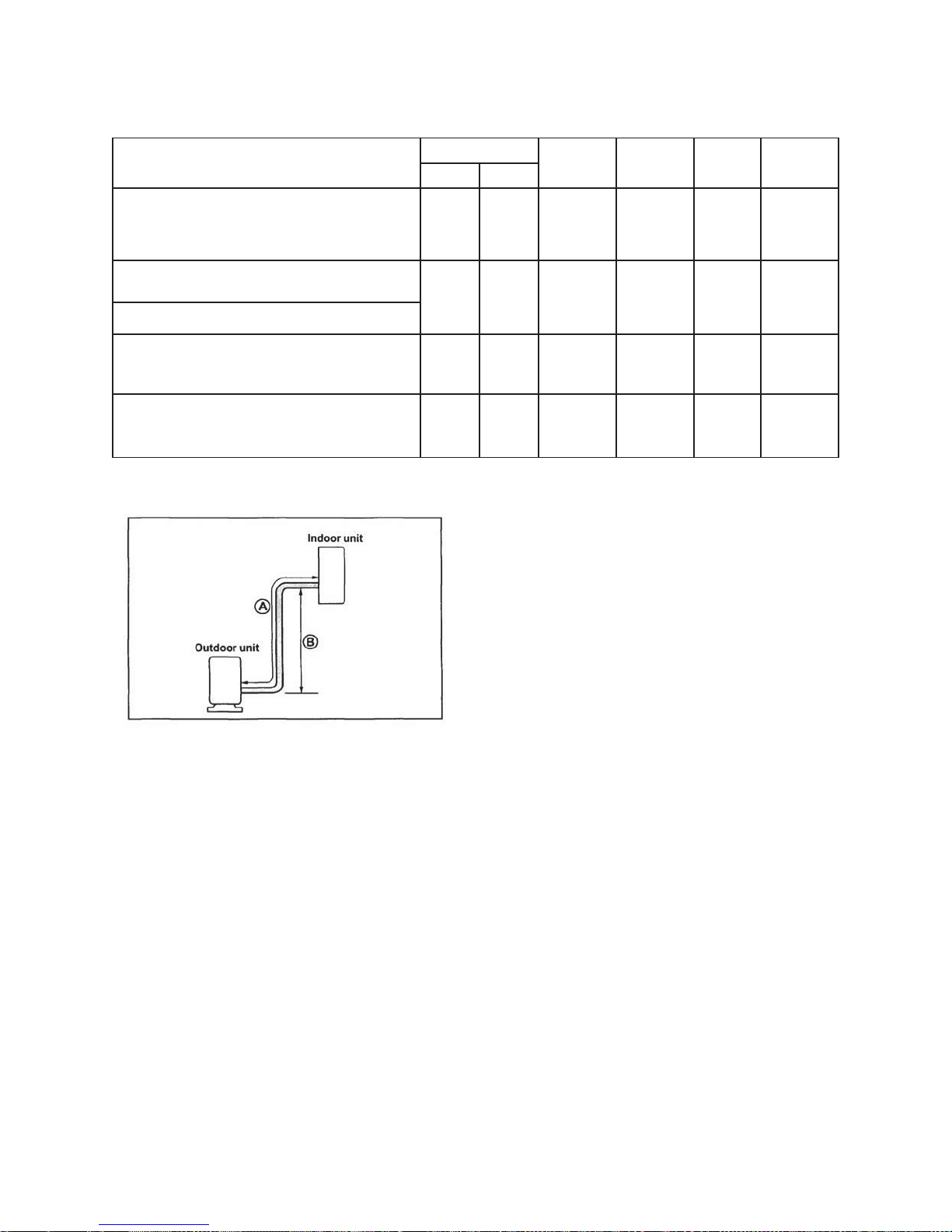
5.3 Pipe length and the elevation
The pipe length and refrigerant amount:
Model
Pipe size
Standard
length
Max.
Elevation
Max.
Length
Additiona
l
Gas
Liquid
ACP-09CH25AERO/I+ ACP-09CH25AERO
/O
3/8’’
(Ф9.52)
1/4’’
(Ф6.35)
5 8 20
20
ACP-12CH35AERO/I + ACP-12CH35AERO/
O
1/
2’’
(Ф12.7)
1/4’’
(Ф6.35)
5 8 20
20
A
CP-12CH35AEXO/I + ACP-12CH35AEX
O/O
A
CP-18CH50AERO/I + ACP-18CH50AER
O/O
1/
2’’
(Ф12.7)
1/4’’
(Ф6.35)
5 10 25
20
A
CP-24CH70AERO/I + ACP-24CH70AER
O/O
5
/8’’
(Ф15.9)
3/8’’
(Ф9.52)
5 10 25
40
Caution:
The capacity test is based on the standard length and the maximum permissive length is based on the
system reliability.
 Loading...