

Vivax ACP-09PT25AEB Service Manual

ACP-09PT25AEB
Service
manual
ENG
RoHS
NNO-1/09


Content
CONTENT
1 Safety precaution .....................................................................................................1
1.1 Installation ........................................................................................................................... 1
1.2 Caution................................................................................................................................ 1
1.3 Operational.......................................................................................................................... 1
2 Out dimension ..........................................................................................................3
3 Display.......................................................................................................................5
3.1 LED display .........................................................................................................................5
3.2 LCD display.........................................................................................................................5
4 Refrigerant cycle diagram .......................................................................................6
5 PCB drawing & wiring diagram ...............................................................................7
5.1 9K Model ............................................................................................................................. 7
5.2 12K Model ............................................................................................................................7
6 Installation detail ......................................................................................................8
6.1 Position requirement for installation .................................................................................... 8
6.2 Preparation work ................................................................................................................. 8
6.3 Installation in a double-hung sash windows ........................................................................ 9
6.4 Installation in a sliding sash windows................................................................................ 10
7 Features ..................................................................................................................12
8 Basic test procedure ..............................................................................................13
8.1 Defective compressor ....................................................................................................... 13
8.2 Sealed refrigeration system repairs................................................................................... 14
8.3 Fan motor.......................................................................................................................... 16
8.4 Capacitor........................................................................................................................... 17
9 Characteristic of temperature sensor...................................................................18
10 Trouble shooting .................................................................................................19

Safety Precaution
1
1 Safety precaution
1.1 Installation
For electrical work, contact the dealer, seller, a qualified electrician, or an Authorized
service center.
Do not disassemble or repair the product by yourself.
Sharp edges could cause injury, be especially careful of the case edges and the fins on the
condenser and evaporator.
Be sure the installation area does not deteriorate with age.
Take care to ensure that power cable could not be pulled out or damaged during operation.
Do not place anything on the power cable.
Do not plug or unplug the power supply plug during operation.
Do not store or use flammable gas or combustible near the product.
When flammable gas leaks, turn off the gas and open a window for ventilation before turn
the product on.
If strange sounds, or small or smoke comes from product. Turn the breaker off or
disconnect the power supply cable as soon as possible.
When the product is soaked (flooded or submerged), contact an Authorized service center.
Be caution that water could not enter the product.
Turn the main power off when cleaning or maintaining the product.
When the product is not be used for a long time, disconnect the power supply plug or turn
off the breaker.
1.2 Caution
Always check for gas (refrigerant) leakage after installation or repair of product.
Install the drain hose to ensure that water is drained away properly.
Keep level even when installing the product.
Do not install the product where the noise or hot air from the outdoor unit could damage
the neighborhoods.
Use two or more people to lift and transport the product.
Do not install the product where it will be exposed to sea wind (salt spray) directly.
1.3 Operational
Do not expose the skin directly to cool air for long periods of time. (Do not sit in the draft).
Do not use the product for special purposes, such as preserving foods, works of art, etc. It
is a consumer air conditioner, not a precision refrigerant system.
Do not block the inlet or outlet of air flow.
Use a soft cloth to clean. Do not use harsh detergents, solvents, etc.
Do not touch the metal parts of the product when removing the air filter. They are very
sharp.
Do not step on pr put anything on the product. (Outdoor units)
Always insert the filter securely. Clean the filter every two weeks or more often if
necessary.

Safety Precaution
2
Do not insert hands or other object through air inlet or outlet while the product is operated.
Do not drink the water drained from the product.
Use a firm stool or ladder when cleaning or maintaining the product.
Replace the all batteries in the remote control with new ones of the same type. Do not mix
old and mew batteries or different types of batteries.
Do not recharge or disassemble the batteries. Do not dispose of batteries in a fire.
If the liquid from the batteries gets onto your skin or clothes, wash it well with clean water.
Do not use the remote of the batteries have leaked.
Outer dimension
3
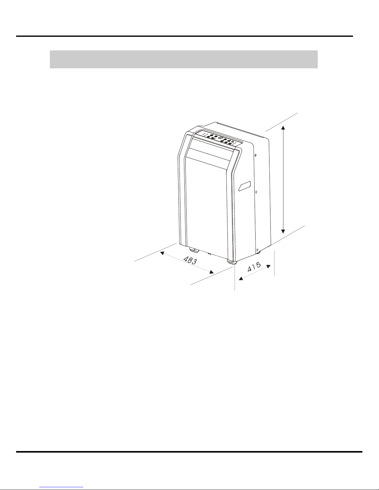
2 Out dimension
Model: ACP-09PT25AEB
8
1
4
External view, part, display
4
3 Display
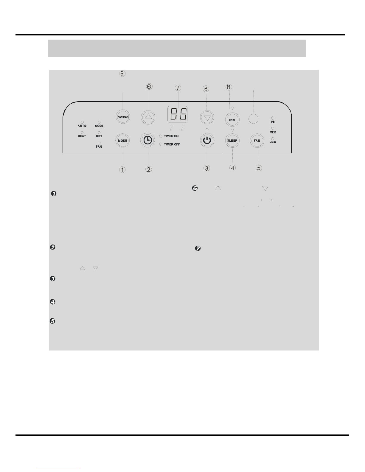
Fig.4
Selects t he app ropriate operating mode.
Each time you press the button, a mode
is selecte d in a seque nce that goes from
AU TO, C OOL, DRY, FAN and HEAT(cooli ng
on ly models wit hout). The mo de ind icator light
illu m inat es under the different mode s etting s
Fig.4.
MODE select button
Used to adjust (incr easing/decreasing)
temperature setting s(1 C/2 F incr ement s)
in a range of 17 C(62 F) to 30 C(88 F) or
the TIMER setting i n a range of 0~24hrs ..
UP( ) and DOWN( ) button
NOTE: The control is capable of displaying
temperature in degre es Fahrenheit or degrees
Celsius. To convert from one to the other, press
and hold the Up a nd Down buttons at the same
time, for 3 seconds.
Used to initiate the AUTO ON start time and
AU TO OFF stop time progra m, in conjucti on
with the & buttons.
TIMER button
Used to initiate the SLEEP o pe ration.
SLEEP button
Power switch on/off
.
POWER button
F
C
Con trol th e f an spe ed. P ress to sel ect the fa n
spe ed i n t hr ee ste ps-LOW , M ED , a nd HI.
T he fa n spe ed in dicator lig ht illumina tes un de r
diff eren t fan setting s.
FAN button
S hows the se t te mp eratu re in CO""
""
or
F and the Auto -t ime r se ttin gs.
While on DRY and FAN modes, it shows
th e r oom t e mp er at u re.
O
LED Display
Error codes:
E1-
E2-
P1-
Room temperature sensor error Unplug the unit and plug it back in.
If error repeats, call for service.
Evaporator temperature sensor error Unplug the unit and plug it back in.
If error repeats, call for service.
Bottom tray is full - Connect the
drain hose a nd drai n the collected
wat e r away. If e rror re peat s, call
fo r ser vi ce.
Rem ote signal receptor
(S om e m ode ls ha v e t he
sig nal re ce ptor on th e
fro nt pa nel , Fi g. 2 )
(The model has no
auto swing feature
withou t this button)
Refrigerant cycle diagram
5
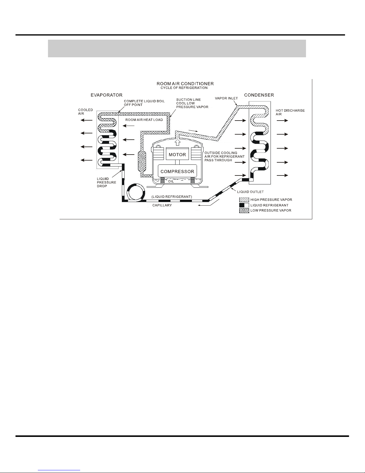
4 Refrigerant cycle diagram
The figure below is a brief description of the important components and their function in
what is called the refrigeration system
 Loading...