

Vivax ACP-07CIFM21GEI, ACP-12CIFM35GEI, ACP-09CIFM25GEI, ACP-18CIFM50GEI Service Manual
ACP-07CIFM21GEI
ACP-09CIFM25GEI
ACP-12CIFM35GEI
ACP-18CIFM50GEI
RoHS
Service
manual
ENG

2
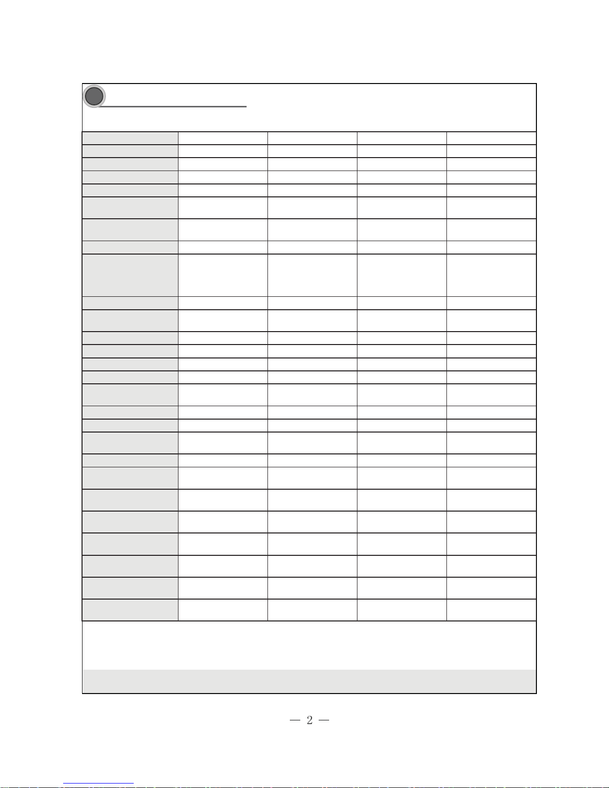
Specifications and Technical Parameters
The above parameters are subject to change without notices, please refer to nameplate for reference.
Model ACP-07CIFM21GEI ACP-09CIFM25GEI ACP-12CIFM35GEI ACP-18CIFM50GEI
Rated Voltage 1PH—220~240V 1PH—220~240V 1PH—220~240V 1PH—220~240V
Frequency(Hz) 50 50 50 50
Cooling Capacity(W) 2100 2600 3500 5300
Heating Capacity(W) 2600 2800 3800 5800
Cooling Air Flow Volume
(m3/h) (SH/H/M/L)
450/390/320/280 450/390/320/280 510/430/380/330 800/680/600/550
Heating Air Flow Volume
(m3/h) (SH/H/M/L)
470/420/340/290 470/420/340/290 570/540/480/400 840/720/660/600
Fan Motor FN20C-PG
Fan Motor Speed (r/min)
(SH/H/M/L)
1250/1150/1000/850 1250/1150/1000/850 1350/1150/1050/900
ࠊދ˖
1380/1150/1050/950
˗ࠊ⛁˖
1400/1200/1100/1000
Output of Fan Motor (w) 10 10 10 20
Input Power of Heater
(w)
////
Fan Motor Capacitor (uF) 1 1 1 1
Fan Motor RLA(A) 0.23 0.23 0.23 0.19
Fan Type-Piece Cross flow fan – 1 Cross flow fan – 1 Cross flow fan – 1 Cross flow fan – 1
Diameter-Length (mm) Ø85 X 615 Ø85X615 Ø85X668 Ø98 X 733
Evaporator
Aluminum fin-copper
tube
Aluminum fin-copper
tube
Aluminum fin-copper
tube
Aluminum fin-copper
tube
Pipe Diameter (mm) Ø7 Ø7 Ø7 Ø7
Row-Fin Gap(mm) 2-1.6 2-1.6 2-1.5 2-1.5
Coil length (l) x height
(H) x coil width (L)
603X264X25.4 603X264X25.4 657X285X25.4 740X301X25.4
Swing Motor Model MP28VB MP28VB MP28VB MP28VB
Output of Swing Motor
(W)
2222
Fus e (A)
PCB 3.15A
Transformer 0.2A
PCB 3.15A
Transformer 0.2A
PCB 3.15A
Transformer 0.2A
PCB 3.15A
Transformer 0.2A
Sound Pressure Level
dB (A) (SH/H/M/L)
38/35/32/29 38/35/32/29 40/35/33/30 46/43/38/34
Sound Power Level dB
(A) (SH/H/M/L)
48/45/42/39 48/45/42/39 50/45/43/40 56/53/48/44
Dimension (W/H/D) (
mm)
815X267X165 815X267X165 872X283X178 960X300X195
Dimension of Package
(L/W/H)( mm )
890X344X260 890X344X260 935X374X260 1035X390X280
Net Weight /Gros s
Weight (kg)
11/13 11/13 12/15 13/18
3
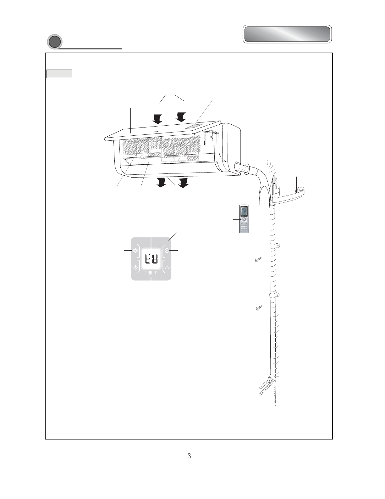
Part name
Indoor unit
Front panel
Air intake
LCD display
Filter
Guide louver board
Air outlet
Wireless remote control
Displayer
Cool
Dry
Heat
Power/Run
Window receiver
Setting temp.
Wrapping Tape
Wall pipe
Artful Series
4
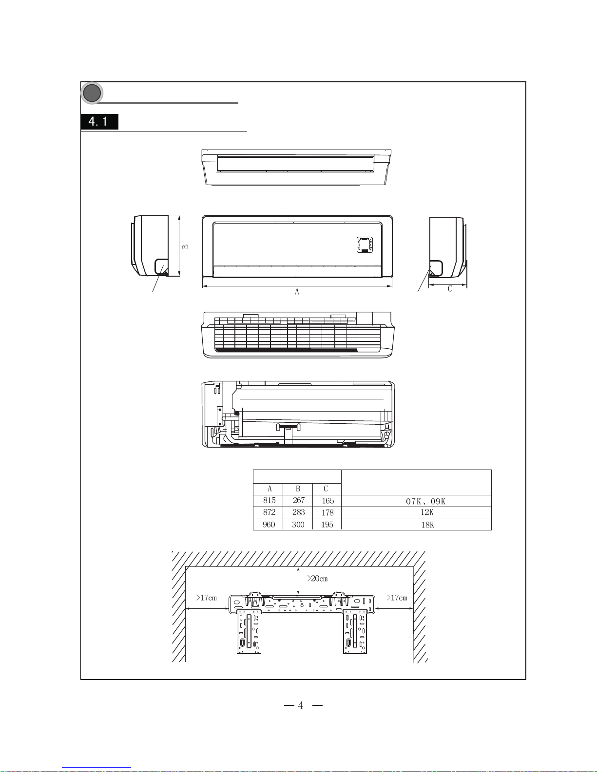
Outline and dimension
Left tube exit Right tube exit
Unit: mm
Dimension
Applicable models
Ceiling
Wall-Mounting Plate
Outline and installation dimension
5
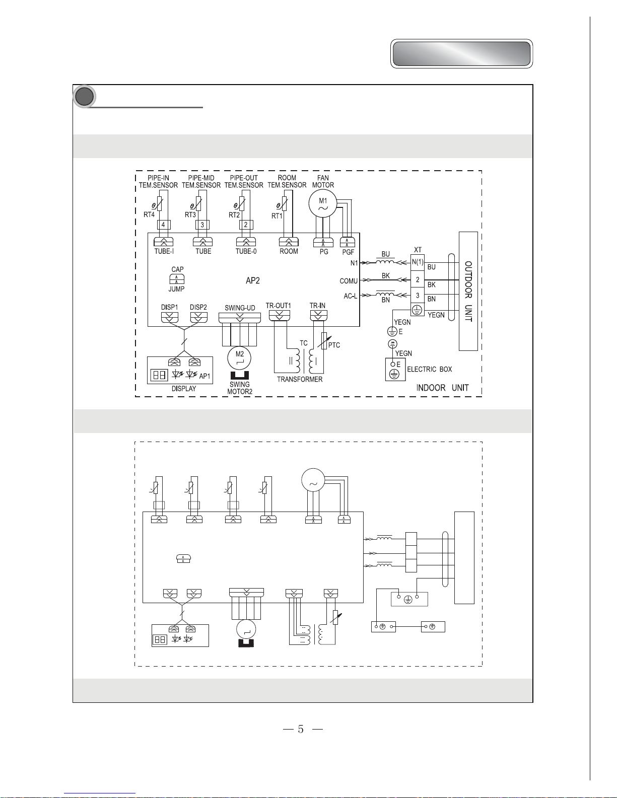
ACP-07CIFM21GEI ACP-09CIFM25GEI ACP-12CIFM35GEI
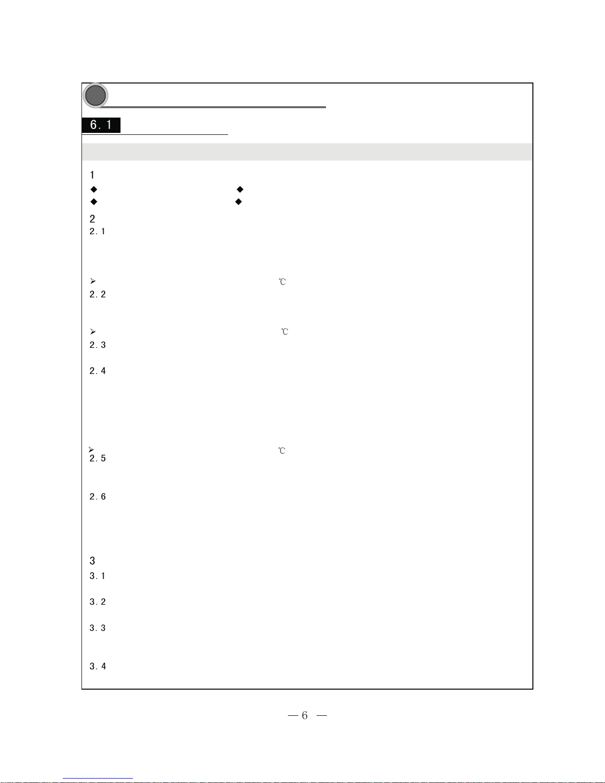
Wiring diagram
The circuit diagrams are subject to change without notice, please refer to the one supplied with the unit.
Artful Series
ELECTRIC BOX
II
III
EVAPORATOR
EARTHING PANEL
AC-L
BK
INDOOR UNIT
BK
PIPE-OUT
DISP1
AP1
DISPLAY
ROOM
TUBE
TR-OUT
M2
SWING-UD
TRANSFORMER
I
TR-IN
TC
ROOM
RT3
0
AP2
BN
PG
RT4
0
M1
BU
FA N
OUTDOOR UNIT
BN
2
YEGN
3
BU
XT
N(1)
PIPE-MID
0
RT2
0
RT1
PIPE-IN
SWING
MOTOR2
COMU
PTC
TUBE-I TUBE-O
DISP2
N1
PGF
MOTOR
YEGN
324
CAP
JUMP
E
YEGN
E
E
TEM.SENSOR TEM.SENSOR TEM.SENSOR TEM.SENSOR
ACP-18CIFM50GEI
Manual of functions of remote controller and operation method
Manual of functions of remote controller
Temperature parameter
Basic Functions
Cooling Mode
DRY Modes
Fan Mode
Heating Mode
Auto mode
Sleep
Others
Buzzer
Auto button
Auto fan speed control
Modes confliction
The air conditioner will send out Hua alert when it is energized or receives a control command.
Under this mode, the setting temperature range is 16-30 .
Under this mode, the setting temperature range is 16-30 .
Under Fan mode, only the indoor fan runs. in Auto mode, it will run in Cool condition. It will run at Cool Auto fan condition.
Room ambient temperature (Tamb)
(1) Fan motor will run at low fan speed, swing motor will run at its presetting status.
(2) Outdoor unit malfunction or protection unit stop, indoor unit will keep original running status,
and display the malfunction indication.
(1) Fan motor, swing motor run at presetting status.
(3) Modes confliction indoor unit will stop to run.
(2) Outdoor unit malfunction or protection unit will stop, indoor unit will keep original
running status, LCD malfunction indicates.
In this mode, the system selects COOL, HEAT and FAN mode automatically according to the change of
ambient temperature. The protectionfunction is the same with that of COOL/HEAT mode.
(1)At Heat mode, the unit enters into opening status, the indoor unit enters into anti-cool wind; when the unit enters into stopping status,
and indoor fan will start up and enters into blowing surplus heat.
(2) Protection function, at Heat mode, due to the malfunction the compressor stops running (including any sensor malfunction), indoor unit
blows surplus heat.
(3) Anti-cool wind: indoor fan will run after 2mins delayed.
Blowing surplus heat: Indoor fan will stop running after 60s and running at the speed before it stop, the fan speed can not be changed.
Blowing surplus heat, the guide board opened at minimum angle.
(4) When defrosting, oil return, indoor unit will stop do not blow surplus heat. During defrosting, oil return procedure and quit 3mins will
not detect all the sensor malfunction.
Under this mode, the setting temperature range is 16-30 .
If indoor received the information modes confliction position 1 of outdoor unit, indoor unit overload will stop (Indoor fan motor, swing),
malfunction indication will be displayed, the mode sent to outdoor unit is still the mode that received by the remote control.
If timer on has arrived, if indoor received the information modes confliction position 1 of outdoor, indoor overload(indoor fan motor,swing)
, the malfunction display, the mode sent to outdoor unit is still the mode that received by the remote control.
When turn off the unit, press this button, the whole unit will run at auto mode, indoor fan motor will run in auto fan speed, turn on the swing.
At unit turns on, press the Auto button that the unit will turns off.
Under Cool, Heat, Fan modes, indoor fan will accord to the ambient temperature select Hig, Mid, Low three speeds, the dehumidifing mode
auto fan speed is low. The switch of each fan mode should be 3mins and 30s.
Indoor unit copper tube surface temp.
(Tcopper)
Evaporator inlet tube temp (Tinlet)
Evaporator outlet tube temp (Tout)
The following function manual, the temperature unit is centigrade, if there is Fahrenheit, there will be TF=TC X1.8+32.
 Loading...