

Vivato VLJ24WFSW Users Manual

™
Your Corporate LogoHere
Vivato 2.4 GHz Wi-Fi Switch User Guide
Manual Part Number: 720-00381-01
Printed in U.S.A.
Copyright © 2002 Vivato 2.4 GHz Wi-Fi Switch User Guide i

Copyright © 2002 Vivato, Inc.
All rights reserved. No part of this document may be reproduced in any form or by any means, electronic or mechanical,
including photocopying, recording, or by any information storage and retrieval system, without written permission from
Viv ato, In c.
Who Should Read This Book?
The Vivato Wi-Fi Switch is a new category of Wi-Fi products. Anyone installing this product, configuring this product for
operation, or performing network management operations involving this product, should read this document before working
with the Wi-Fi switch.
ii Vivato 2.4 GHz Indoor Wi-Fi Switch User Guide Copyright © 2002

Safety Information
Safety Information
You must heed any and all safety precautions and warnings in this document or indicated on the Vivato
2.4 GHz Wi-Fi Switch whenever you are operating or servicing this product. Failure to comply with all
precautions and warnings found in this document violates the design, manufacture, and intended use
requirements of the product. Vivato, Inc. assumes no liability for the operator’s failure to obey these
warnings and cautions.
The person installing the Vivato Wi-Fi Switch must be qualified by Vivato, Inc. or by a Vivato
authorized reseller.
This product must only be serviced by qualified Vivato personnel or its
certified agent.
Ground the equipment: This product uses a protective earth ground terminal. An uninterruptible safety
earth ground must be provided from the mains power source to the product’s input wiring terminals or
to the supplied power cable.
Do not operate this product in an explosive atmosphere or in the presence of flammable gases or
fumes, or in the presence of unshielded blasting caps.
To protect against fire, replace any fuses in the product with those of the same voltage, current rating,
and type. Never short-circuit fuse holders or use modified fuses.
Keep away from energized circuits. Only qualified Vivato service personnel or its certified agent may
remove the outer covers of the product. Hazardous voltages may be present any time a cover is removed,
even if the product is not turned on.
Do not operate this product if damage is indicated. Refer servicing or repair to qualified Vivato
personnel or its certified agent.
Do not service or adjust this product by yourself. It is recommended that someone else is present who
can render first aid in the event that electrical shock or other injury occurs.
Do not substitute any parts or modify the product. Any unauthorized changes to the product could
result in compromising the safety features or the correct operation of the product. Refer any service or
repair to authorized Vivato personnel or its certified agent.
FCC Declaration of Conformity
Responsible Party
Manufactured by Vivato, Inc.
139 Townsend Street, Suite 200
San Francisco, CA 94107, USA
Phone: (415) 495-1111, Fax (425) 495-6430
Product: Vivato, Inc. 2.4 GHz Wi-FI Switch, model VLJ24WFSW
This product is intended for home or office use.
Copyright © 2002 Vivato 2.4 GHz Wi-Fi Switch User Guide iii

Safety Information
The Vivato Wi-Fi Switch has been evaluated under FCC Bulletin OET 65C and found to be compliant
to the requirements set forth in CFR 47 15.247 (b) (4) addressing RF Exposure from radio frequency
devices. The Wi-Fi Switch should be at least 20 cm (7.8 in.) from people when operating.
• FCC Indoor exposure limits for 2.4 GHz ISM Part 15 devices: 1mW/cm
2
at 20 cm distance from
antenna face.
• Vivato Wi-Fi Switch worst case exposure (OET 65 upper bound method): 0.247 mW/cm
2
at
20 cm distance from antenna face with all three channels transmitting simultaneously.
• Worst case exposure at 20 cm from antenna face (three channels in adjacent pointing directions
2
at the extreme left or right): <0.13 mW/cm
.
Interference and Equipment Limits
This equipment has been tested and found to comply with the limits pursuant to Part 15 of the FCC
Rules. As such, operation of this equipment may not cause harmful interference and this equipment
must accept any interference received including interference that may cause undesired performance.
This equipment generates, uses, and radiates radio frequency energy, and if not installed and used in
accordance with the instructions, may cause harmful interference. Contact Vivato personnel if
interference is detected.
Note: Warning - This Part 15 radio device operates on a non-interference basis with other devices
operating at this frequency when using the listed equipment. Vivato, Inc. is not responsible for any
interference caused by unauthorized modification or configuration programming of this device or by the
substitution or attachment of antennas or equipment other than that specified by Vivato, Inc. Violations
of these conditions will void the user's authority to operate this device. This device must not be
co-located with other transmitters and antennas.
This equipment has been tested and found to comply with the limits of a Class B digital device, pursuant
to Part 15 of the FCC Rules. These limits are designed to provide reasonable protection against harmful
interference when the equipment is operated in a residential environment. This equipment generates,
uses, and radiates radio frequency energy, and if not installed and used in accordance with the
instructions, may cause harmful interference. However, there is no guarantee that interference will not
occur. If this equipment does cause interference to radio or television reception, which can be
determined by turning the equipment off and on, the user is encouraged to correct the interference by
one of the following measures:
• Reorient or relocate the receiving antenna.
• Increase separation between the equipment and receiver.
• Connect the equipment to an outlet on a circuit different from which the receiver is connected.
• Consult the dealer or an experienced radio/TV technician.
iv Vivato 2.4 GHz Wi-Fi Switch User Guide Copyright © 2002
Conventions Used in This Document
Safety Information
Conventions Used in This Document
The following conventions are used in this document:
Table 1 — Document Conventions
Convention Format What it Indicates
computer entry Text that you enter on the Wi-Fi switch’s web page or on a terminal when using the
command line interface (CLI).
> The > symbol indicates a menu navigation selection. For example, “select File > Save “
means “select the File menu, and then select the Save option.”
Labels Items in a menu, such as the tabs shown on the configuration web pages.
Switch,Wi-Fi Switch Both terms refer to the Vivato 2.4 GHz Wi-Fi Switch unless otherwise noted.
<MD5|DES> Indicates that you need to enter either term (MD5 or DES). Do not enter the <|> symbols.
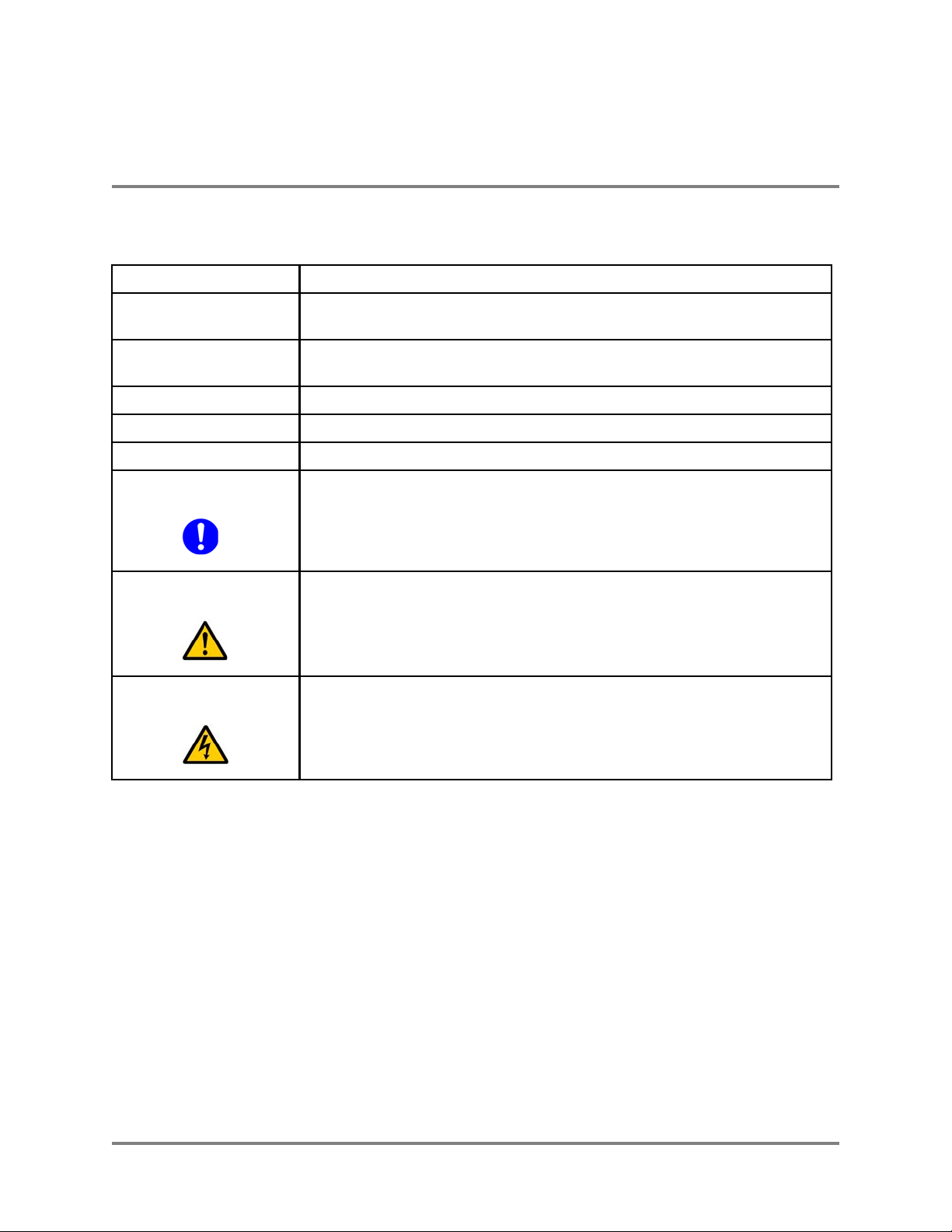
This symbol identifies critical information concerning Vivato Wi-Fi Switch operation.
Important
Failure to comply with this information may degrade or prevent Wi-Fi operation.
Caution
Warning
This symbol identifies information that must be complied with to keep the Wi-Fi Switch
from being damaged.
This symbol identifies information that must be complied with to reduce the possibility
of electrical shock or other injury.
Copyright © 2002 Vivato 2.4 GHz Wi-Fi Switch User Guide v

Contact Information
Safety Information
Contact Information
For customer support:
E-mail: support@vivato.net (use “manuals_feedback@vivato.net” for documentation feedback)
Mail:
Vivato, Inc .
139 Townsend St., Suite 200
San Francisco, CA 94107
To provide feedback on our documentation:
Feedback on the documentation shipped with the Vivato 2.4 GHz Wi-Fi Switch is greatly appreciated,
and will always be reviewed by our Technical Publications department. Please send your suggestions to
manuals_feedback@vivato.net or click on the “Send Documentation Feedback” link at the bottom
of each online documentation page on the Vivato CD. (Please use the support@vivato.net address for
product support issues.)
vi Vivato 2.4 GHz Wi-Fi Switch User Guide Copyright © 2002

Warranty and End User License
VIVATO END USER LIMITED WARRANTY AND LICENSE TERMS
LIMITED WARRANTY
Vivato warrants that for a period of one year from the date of shipment from Vivato, the hardware of the
Vivato Products will be free from defects in material and workmanship under normal use. This limited warranty
extends only to End Users as original purchasers.
REMEDY
For all Vivato Products or components thereof that do not comply with the warranty provided above, Vivato
will either repair or replace such non-compliant Vivato Products or components thereof.
All warranty claims shall be directed to Vivato’s technical assistance center at 1-415-495-1111. Vivato or its
agent shall have the right to inspect the Vivato Product being claimed as non-compliant with the warranty provided
above following any warranty claim, with reasonable notice during normal working hours. Vivato’s technical
assistance center will issue Return Material Authorizations (RMA’s) for all Vivato Products or components thereof
that are acknowledged by Vivato as qualifying for the warranty remedies specified herein.
After receiving an RMA for a Vivato Product, End User shall ship such Vivato Product or component
thereof, clearly identifying it with its RMA, to Vivato’s repair facility in its original shipping cartons or equivalent,
freight prepaid. Vivato Products damaged during return shipment due to improper packing will not be covered by
this warranty. Following receipt of the Vivato Product accompanied by an RMA number, Vivato, at its discretion,
may repair or replace such product, and shall return the repaired or replaced product to End User freight prepaid by
Vivato. Vivato at its option may replace any returned Vivato Product or component thereof with equivalent or better,
new or refurbished products or parts. The remainder of the original warranty coverage shall apply to such repaired or
replacement products.
If the product defect is found by Vivato to have been caused by misuse or abnormal operating conditions,
repairs and/or replacement will be billed to End User’s account. In such event, an estimate of the cost of repairs
and/or replacement will be submitted to End User for approval before the work is started. If the returned Vivato
Product is found by Vivato to be in compliance with the warranty above, Vivato may charge a fee for the evaluation,
which may include reasonable travel and expenses, if applicable.
LIMITATIONS OF WARRANTY
This warranty does not apply to Vivato Products which exhibit failures or non-compliance resulting from: a)
improper handling, installation, repair, maintenance or use; b) damage caused by vandalism, severe weather,
lightning, chemical hazards, fire, contact with high-voltage power lines or other electrical stress; c) repairs,
modifications, or any alterations performed or attempted by End User or any third party, unless authorized by Vivato
as stated below; d) use in conjunction with equipment which is not compatible with Vivato Products; e)
documentation errors; or f) software errors which do not cause Vivato Products to be materially non-compliant with
their written specifications.
Vivato does not warrant or accept any responsibility in connection with any of its products which have been
repaired or altered by anyone other than Vivato, unless Vivato has specifically authorized in writing in advance such
repairs or alterations. In the event of any such unauthorized repairs or alterations, this warranty shall become void.
No agent, distributor, Reseller or representative is authorized to make any warranties or to assume any liabilities on
behalf of Vivato.
Copyright © 2002 Vivato 2.4 GHz Wi-Fi Switch User Guide vii

Vivato shall make the final determination as to the existence and cause of any alleged defect. Non-payment
of invoices for products, within the stated terms, shall cause this warranty to be suspended until late invoices are fully
paid.
Minor or non-substantive defects or deviations from specifications, or documentation errors or omissions
shall not constitute a warranty defect. Vivato reserves the right, without notice to End User, to discontinue products,
and to change product specifications provided such changes in specifications do not adversely affect the performance
of products scheduled for future delivery under an existing purchase contract.
End User’s sole remedy with respect to any warranty or defect in the Vivato Products is as stated above.
EXCEPT AS SPECIFIED HEREIN, VIVATO MAKES NO OTHER WARRANTIES WITH RESPECT TO
VIVATO PRODUCTS AND DISCLAIMS AND EXCLUDES ALL OTHER WARRANTIES, EXPRESS OR
IMPLIED, TO THE EXTENT ALLOWED BY APPLICABLE LAW, INCLUDING WARRANTIES OF
MERCHANTABILITY, FITNESS FOR A PARTICULAR PURPOSE, WARRANTIES OF NON-INFRINGEMENT
OR WARRANTIES ARISING FROM A COURSE OF DEALING, USAGE, OR TRADE PRACTICE. ALL SUCH
WARRANTIES ARE HEREBY EXPRESSLY DISCLAIMED. VIVATO DOES NOT WARRANT THAT THE
VIVATO PRODUCTS OR VIVATO SOFTWARE ARE ERROR-FREE OR THAT OPERATION OF THE VIVATO
PRODUCTS OR VIVATO SOFTWARE WILL BE SECURE OR UNINTERRUPTED AND VIVATO HEREBY
DISCLAIMS ANY AND ALL LIABILITY ON ACCOUNT THEREOF.
LIMITATION OF LIABILITY
NOTWITHSTANDING ANYTHING ELSE IN THIS WARRANTY, VIVATO SHALL NOT BE LIABLE
UNDER ANY PROVISION OF THIS WARRANTY OR UNDER ANY CONTRACT, NEGLIGENCE, STRICT
LIABILITY OR OTHER LEGAL OR EQUITABLE THEORY (A) FOR ANY AMOUNTS IN EXCESS OF THE
AGGREGATE AMOUNTS PAID BY END USER TO VIVATO FOR THE PRODUCT, OR (B) FOR ANY
INCIDENTAL OR CONSEQUENTIAL DAMAGES, OR (C) FOR THE COSTS OF PROCUREMENT OF
SUBSTITUTE PRODUCTS OR SERVICES.
viii Vivato 2.4 GHz Wi-Fi Switch User Guide Copyright © 2002

END USER LICENSE
PLEASE READ THIS BEFORE INSTALLING, USING OR
DOWLOADING VIVATO SUPPLIED PRODUCT OR
SOFTWARE.
BY INSTALLING, USING OR DOWLOADING VIVATO SUPPLIED PRODUCT OR SOFTWARE, YOU
ARE CONSENTING TO BE BOUND BY THIS LICENSE. IF YOU DO NOT WANT AGREE TO ALL OF
THE TERMS OF THIS LICENSE THEN: A) DO NOT INSTALL, USE OR DOWNLOAD THE VIVATO
SUPPLIED PRODUCT OR SOFTWARE, AND B) YOU MAY RETURN THE VIVATO SUPPLIED
PRODUCT OR SOFTWARE FOR A FULL REFUND. YOUR RIGHT TO RETURN AND REFUND
EXPIRES AFTER 30 DAYS AFTER PURCHSE FROM VIVATO OR AN AUTHORIZED VIVATO
RESELLER, AND APPLIES ONLY IF YOU ARE THE ORIGIAL PURCHASER.
The following terms govern your use of the Vivato Product or Software except to the extent to a particular
program: a) is the subject of a separate written agreement with Vivato or b) includes separate “click-on”
license agreement as a part of the installation and/or download process. To the extent of a conflict between the
provisions of the foregoing documents, the order of precedence shall be 1) the written agreement, 2) the
click-on agreement, and 3) this End User License.
1. End user shall be granted a limited nonexclusive and nontransferable license to use the Vivato Products
(including the Vivato Software) solely for its own internal business operations solely in the Territory.
Except as expressly permitted by such license, End User shall not use, reproduce, make, have made, import,
offer for sale, sell, modify, adapt, rent, lease, loan, create derivative works of, display, perform, distribute,
sublicense or otherwise exploit the Vivato Products in any way for any purpose.
2. End User acknowledges that the Vivato Products contain trade secrets of Vivato, and to protect them, End
User shall not reverse engineer, disassemble, decompile, or otherwise attempt to derive the source code of
the Software or algorithms or other aspects of the Vivato Products.
3. End User acknowledges that the Vivato Products are covered by patent, copyright, trade secret and other
intellectual property rights. No right, title or interest, expressed or implied, in or to the Vivato Software,
including without limitation patent, copyright, trade secret or other intellectual property rights therein, other
than the limited license granted above, is transferred from Vivato to End User. Title to and ownership of the
Vivato Software shall remain with Vivato and its licensors (if any). End User shall not alter or erase any
proprietary notices appearing on the Vivato Products and shall reproduce all such proprietary notices on the
Vivato Products.
4. End User acknowledges that the Vivato Products contain confidential and proprietary information belonging
to Vivato and its licensors (if any). End User shall exercise at least the same degree of care, but in no event
less than a reasonable degree of care, to safeguard the confidentiality of Vivato and its licensors’
confidential and proprietary information as End User would exercise with respect to End User’s own
confidential information.
5. The Vivato Products are being provided to End User with the limited warranty specified in the Product
Warranty, incorporated by reference herein. EXCEPT AS SPECIFIED IN THE PRODUCT WARRANTY,
VIVATO MAKES NO OTHER WARRANTIES WITH RESPECT TO VIVATO PRODUCTS AND
Copyright © 2002 Vivato 2.4 GHz Wi-Fi Switch User Guide ix

DISCLAIMS AND EXCLUDES ALL OTHER WARRANTIES, EXPRESS OR IMPLIED, TO THE
EXTENT ALLOWED BY APPLICABLE LAW, INCLUDING WARRANTIES OF
MERCHANTABILITY, FITNESS FOR A PARTICULAR PURPOSE, WARRANTIES OF
NON-INFRINGEMENT OR WARRANTIES ARISING FROM A COURSE OF DEALING, USAGE, OR
TRADE PRACTICE. ALL SUCH WARRANTIES ARE HEREBY EXPRESSLY DISCLAIMED.
VIVATO DOES NOT WARRANT THAT THE VIVATO PRODUCTS OR VIVATO SOFTWARE ARE
ERROR-FREE OR THAT OPERATION OF THE VIVATO PRODUCTS OR VIVATO SOFTWARE WILL
BE SECURE OR UNINTERRUPTED AND VIVATO HEREBY DISCLAIMS ANY AND ALL
LIABILITY ON ACCOUNT THEREOF. End User’s sole remedy with respect to any breach of the Product
Warranty shall be the remedies specified in the Product Warranty.
6. NOTWITHSTANDING ANYTHING ELSE IN THIS WARRANTY, VIVATO SHALL NOT BE LIABLE
TO END USER OR ANY THIRD PARTY UNDER ANY PROVISION OF THE WARRANTIES HEREIN
OR UNDER ANY CONTRACT, NEGLIGENCE, STRICT LIABILITY OR OTHER LEGAL OR
EQUITABLE THEORY (A) FOR ANY AMOUNTS IN EXCESS OF THE AGGREGATE AMOUNTS
PAID BY END USER TO VIVATO FOR THE PRODUCT, OR (B) FOR ANY INCIDENTAL OR
CONSEQUENTIAL DAMAGES, OR (C) FOR THE COSTS OF PROCUREMENT OF SUBSTITUTE
PRODUCTS OR SERVICES, WHETHER OR NOT VIVATO OR ANYONE ELSE HAS BEEN
ADVISED OF THE POSSIBILITY OF SUCH DAMAGES.
x Vivato 2.4 GHz Wi-Fi Switch User Guide Copyright © 2002

Table of Contents
Safety Information ................................................................................................iii
FCC Declaration of Conformity ........................................................................................ iii
Conventions Used in This Document .....................................................................................v
Contact Information .............................................................................................................. vi
Introduction ............................................................................................................ 1
Multi-Channel Operation........................................................................................................1
Basic Service Set Operation ....................................................................................................1
“Out of the Box” Settings........................................................................................................1
Indoor Wi-Fi Switch Installation ..........................................................................3
Shipping Contents....................................................................................................................4
Where to Mount The Indoor Wi-Fi Switch ...........................................................................4
Analyzing Room Shape for Best Coverage .........................................................................5
Ceiling Height Considerations.............................................................................................6
Minimizing Obstructions .....................................................................................................7
Interfering Signal Sources ...................................................................................................7
Environmental Considerations For Indoor Use ...................................................................7
Assembling the Wi-Fi Switch..................................................................................................8
Attaching the Top and Bottom Rails ...................................................................................8
Attaching the End Caps .......................................................................................................9
Attaching the Fabric Cover..................................................................................................9
Cable Routing to the Wi-Fi Switch ......................................................................................10
Mounting the Wi-Fi Switch...................................................................................................11
Mounting Weight Considerations......................................................................................11
Mounting The Wi-Fi Switch on a Wall (Flush Mount) .....................................................11
Mounting the Wi-Fi Switch Using the Optional Corner Mount Kit..................................14
Mains (AC) Power Requirements ........................................................................................17
Connections to the Vivato Wi-Fi Switch..............................................................................17
Media Access Control (MAC) Addresses in the Wi-Fi Switch.........................................18
Outdoor Wi-Fi Switch Installation .....................................................................21
Shipping Contents..................................................................................................................21
Where to Mount The Outdoor Wi-Fi Switch ......................................................................22
Minimizing Obstructions ...................................................................................................23
Interfering Signal Sources .................................................................................................24
Environmental Considerations For Outdoor Use...............................................................24
Mounting the Outdoor Wi-Fi Switch ...................................................................................24
Mounting Weight Considerations......................................................................................25
Outdoor Wi-Fi Switch Dimensions ...................................................................................26
Mounting Hardware...........................................................................................................27
Mains (AC) Power Requirements and Connections ..........................................................31
Data Connections ...................................................................................................................33
Media Access Control (MAC) Addresses in the Wi-Fi Switch.........................................33
Copyright © 2002 Vivato 2300 Series Wi-Fi Switch User Guide xi

Table of Contents
Initial Configuration Using the Built-In Web Pages .........................................35
Steps to Configuring the Vivato Wi-Fi Switch....................................................................35
Summary of Configuration Web Page Features.................................................................36
Default Configuration............................................................................................................36
Configuration Connections ...................................................................................................37
Enabling Your Network Adapter to Access the Wi-Fi Switch..........................................38
Wired Connection to Access the Configuration Web Page...............................................40
Wireless Configuration Connection...................................................................................41
Entering the Initial Configuration Information in the Quick Setup Pages......................43
Switch Selection ................................................................................................................43
Read Password Setup.........................................................................................................44
Enable Password Setup......................................................................................................45
Basic Network Setup .........................................................................................................46
Basic Security Setup ..........................................................................................................47
Wireless Options Setup......................................................................................................48
Rebooting the Wi-Fi Switch ..............................................................................................49
Where Do I Go From Here? ..............................................................................................49
Using the Main Configuration Web Pages .........................................................51
Navigating the Main Web Page Configuration Screens.....................................................51
Status Indicators.................................................................................................................52
Home .......................................................................................................................................53
Summary............................................................................................................................53
Quick Setup........................................................................................................................54
Network Configuration Web Pages ....................................................................55
Network Settings ....................................................................................................................55
Summary............................................................................................................................55
Ethernet Interfaces .............................................................................................................55
Wireless Interfaces.............................................................................................................56
Bridges ...............................................................................................................................60
VLANs...............................................................................................................................62
Routes ...............................................................................................................................65
Security Configuration Web Pages .....................................................................67
Configuring Security .............................................................................................................67
Wired Equivalent Privacy (WEP)......................................................................................68
EAP....................................................................................................................................69
Point to Point Tunneling Protocol (PPTP).........................................................................72
Optimizing Your Wireless Client For Secure Communications .......................................74
Monitoring Rogue APs, Clients, and System Operations .................................79
System Messages ....................................................................................................................79
xii Vivato 2330 Wi-Fi Switch User Guide Copyright © 2002

Table of Contents
SNMP Monitoring..................................................................................................................79
Base SNMP Options ..........................................................................................................80
Create an SNMP Community ............................................................................................81
SNMP Version 3 Configuration Settings...........................................................................81
SNMP Version 2 Trap Sinks .............................................................................................83
SNMP Version 1 Traps......................................................................................................83
Rogue Access Point Detection (RAPD) and Notification ...................................................83
Associated Clients ..................................................................................................................84
Services, Password, Config, and Firmware Web Pages .................................... 87
Summary.................................................................................................................................87
Services ...................................................................................................................................88
Set System Hostname ........................................................................................................88
Reboot System ...................................................................................................................88
SSH Services Configuration ..............................................................................................88
HTTP Services Configuration ...........................................................................................89
Password .................................................................................................................................89
Config......................................................................................................................................89
Returning to Factory Configuration Defaults ....................................................................90
Firmware ................................................................................................................................91
Local Firmware Options ....................................................................................................91
Remote Firmware Options.................................................................................................91
Quick Setup ............................................................................................................................92
Diagnostics and Help Web Screens .....................................................................93
Diagnostics..............................................................................................................................93
Ping ....................................................................................................................................93
Traceroute ..........................................................................................................................93
Help .........................................................................................................................................94
Command Line Interface ..................................................................................... 97
Command Levels....................................................................................................................97
Connections and Terminal Settings .....................................................................................98
Accessing the CLI ..................................................................................................................99
Accessing the Configuration Level..................................................................................100
Configuration Example .......................................................................................................101
Navigating the CLI ..............................................................................................................103
Moving the Cursor Around on the Command LIne.........................................................103
Using the “?” to Get Online Command Help ..................................................................103
Using the Tab Key to Complete a Command ..................................................................104
Command Mode Access and Prompts .............................................................................104
Command Conventions....................................................................................................104
Read Level Command Descriptions...................................................................................105
enable ...............................................................................................................................105
Copyright © 2002 Vivato 2300 Series Wi-Fi Switch User Guide xiii

Table of Contents
exit ...................................................................................................................................105
Ping ..................................................................................................................................105
Show Commands .............................................................................................................106
traceroute <ipaddress|hostname>.....................................................................................115
Enable Level Command Descriptions................................................................................115
configure [terminal] .........................................................................................................116
Commands for Managing Configuration Files ................................................................116
Configure System (boot system flash:)............................................................................119
Configure Clock...............................................................................................................119
Configure Crypto (Generate Keys)..................................................................................120
Configure EAP Commands .............................................................................................120
Configure No EAP Commands........................................................................................123
Configure Enable Secret ..................................................................................................123
Configure HTTP-Server ..................................................................................................124
Configure Interface Commands.......................................................................................124
Configure No Interface Commands.................................................................................139
Configure IP Command ...................................................................................................140
Configure Log Commands...............................................................................................141
Configure PPTP Commands............................................................................................141
Configure No PPTP Commands ......................................................................................143
Configure RAPD..............................................................................................................145
Configure SNMP-Server Commands ..............................................................................145
Configure No SNMP-Server Commands ........................................................................147
Configure Username Admin (Read Level) Secret...........................................................148
Configure Vivato Packet Shaping....................................................................................148
disable ..............................................................................................................................148
edit flash: .........................................................................................................................148
exit ...................................................................................................................................149
no <configuration command>..........................................................................................149
reboot ...............................................................................................................................149
Verifying Wi-Fi Operation ................................................................................151
Verification Process .............................................................................................................151
Wireless Client Does Not “Find” the Vivato Wi-Fi Switch ............................................153
Wireless Client Can’t Access Wi-Fi Switch Configuration Web Page ...........................154
Wireless Client Cannot Access the Local Wired Network..............................................155
Wireless Client Cannot Access an Outside Network.......................................................155
Unauthorized Clients Are Able to Associate With The Wi-Fi Switch ............................155
Network Monitoring ..........................................................................................157
SNMP Operations ................................................................................................................157
Supported MIBs...............................................................................................................158
Enabling SNMP Operation ..............................................................................................160
xiv Vivato 2330 Wi-Fi Switch User Guide Copyright © 2002

Table of Contents
Wi-Fi Switch Firmware Updates ...................................................................... 163
Firmware Update Process Using the Command Line Interface......................................163
Firmware Update Example ..............................................................................................164
Point to Point Tunneling Protocol (PPTP) Operation ....................................165
PPTP Configuration ............................................................................................................165
Creating a Bridge Using a VLAN....................................................................................165
Specifying a Secondary IP Address for the Default Bridge ............................................166
Example Configuration....................................................................................................166
Configuring PPTP in Clients ...........................................................................................167
Copyright © 2002 Vivato 2300 Series Wi-Fi Switch User Guide xv

Table of Contents
xvi Vivato 2330 Wi-Fi Switch User Guide Copyright © 2002

Introduction
Multi-Channel Operation
Introduction
The Vivato 2.4 GHz Wi-Fi Switch is a three-channel unlicensed (FCC Part 15) wireless device operating
in the 2.4 GHz band, providing network connections to Wi-Fi (IEEE 802.11b) client devices on up to
three simultaneous channels.
The Vivato Wi-Fi Switch replaces previous micro cellular style Wi-Fi deployments, while providing the
highest level of wireless security, system management, and switching capabilities.
The Wi-Fi Switch’s design allows point-to-point packet transmission to client devices through an
integrated high gain, electronically steered transmitting antenna. The same antenna also functions as a
high gain receiving antenna, allowing the Wi-Fi switch to receive signals from standard 802.11b clients,
even at long distances or with high signal attenuation. This design allows one Wi-Fi Switch to provide
high bit rate network coverage to one or more floors of an office building or any other large space
requiring Wi-Fi coverage.
Both indoor and outdoor versions of the Vivato Wi-Fi Switch are available, providing Wi-Fi service in
almost any environment.
Multi-Channel Operation
The Vivato Wi-Fi Switch can communicate simultaneously on up to three 802.11b channels when used
in areas of light Wi-Fi traffic, and on two channels when used in areas of heavy Wi-Fi traffic.
The Wi-Fi Switch’s 100° antenna pattern is divided into 13 focused areas. If necessary, the channel
assignment and other settings for each area can be changed to optimize overall Wi-Fi operation within
the full antenna pattern.
Basic Service Set Operation
The Wi-Fi Switch supports infrastructure basic service set (BSS) operation, providing all network
communications between Wi-Fi clients and the wired network within the area of coverage. Independent
basic service set (IBSS) operation, where 802.11b clients can communicate directly with each other
without using the Wi-Fi switch, is not supported.
“Out of the Box” Settings
The Wi-Fi Switch is shipped with a default bridge, IP address, channel assignments, and ESSID. These
settings allow configuration changes to be made using the built-in web pages or using the command line
interface (CLI), and connecting through a wired or a wireless link. Refer to "Default Configuration"
on page 36.
Vivato 2.4 GHz Wi-Fi Switch User Guide 1

Introduction
“Out of the Box” Settings
2 Vivato 2.4 GHz Wi-Fi Switch User Guide

Indoor Wi-Fi Switch Installation
Indoor Wi-Fi Switch Installation
The person installing the Vivato Wi-Fi Switch must be qualified by Vivato, Inc. or by a Vivato
authorized reseller.
This section is specific to the Vivato 2.4 GHz Indoor Wi-Fi Switch. See "Outdoor Wi-Fi Switch
Installation" on page 21 for information on installing the outdoor version.
We recommend that you prepare your Vivato 2.4 GHz Indoor Wi-Fi Switch for operation in the
following order:
1 Verify the contents of the shipping container. See "Shipping Contents" on page 4.
2 Register your Vivato Wi-Fi Switch! You can select Register Online Now! here or on the
Vivato CD startup page, or go to http://www.vivato.net/wifiregistration.html.
3 Attach the top and bottom rails, end caps, and fabric cover. See "Assembling the Wi-Fi
Switch" on page 8.
4 Fill out the Vivato Wi-Fi Switch Configuration Worksheet.
5 Analyze your site to estimate the best place to mount the Wi-Fi Switch. See "Where to
Mount The Indoor Wi-Fi Switch" on page 4.
6 Configure the Wi-Fi Switch. You can configure the Switch before or after mounting it.
However, it may be more convenient to perform the initial configuration before mounting the
Switch on a wall. See "Initial Configuration Using the Built-In Web Pages" on page 35.
7 If power and/or LAN connections are to be routed above the Wi-Fi Switch, route the cables
on the rear panel before mounting. See "Cable Routing to the Wi-Fi Switch" on page 10.
8 Mount the Wi-Fi Switch. See "Mounting the Wi-Fi Switch" on page 11.
9 If not already connected, connect the Wi-Fi Switch to mains (AC) power and your LAN. See
"Connections to the Vivato Wi-Fi Switch" on page 17
10 Verify Wi-Fi Switch operation using your Wi-Fi client. See "Verifying Wi-Fi Operation"
on page 151.
Vivato 2.4 GHz Wi-Fi Switch User Guide 3
Indoor Wi-Fi Switch Installation
Shipping Contents
Shipping Contents
The following items are included in the shipping container with the Vivato 2.4 GHz Indoor Wi-Fi
Switch:
• Vivato Wi-Fi Switch.
• DB-9 null modem cable
• 100 Base-T Ethernet cable (white)
• 100 Base-T cable cross-over Ethernet (red)
• Power cable
• Mounting kit brackets (2), flange nuts (4), and hollow wall anchors (4)
• Fabric dress cover
• Top dress panel support rail
• Bottom dress panel support rail
• End caps (2)
• Quick Configuration Guide (11” x17” sheet)
• User Guide CD-ROM: includes user documentation, management information bases (MIBs),
and PDF copies of the Quick Configuration sheet and the Command Line Interface Quick
Reference.
• Command Line Interface Quick Reference (11” x 17” sheet, 4-fold)
Where to Mount The Indoor Wi-Fi Switch
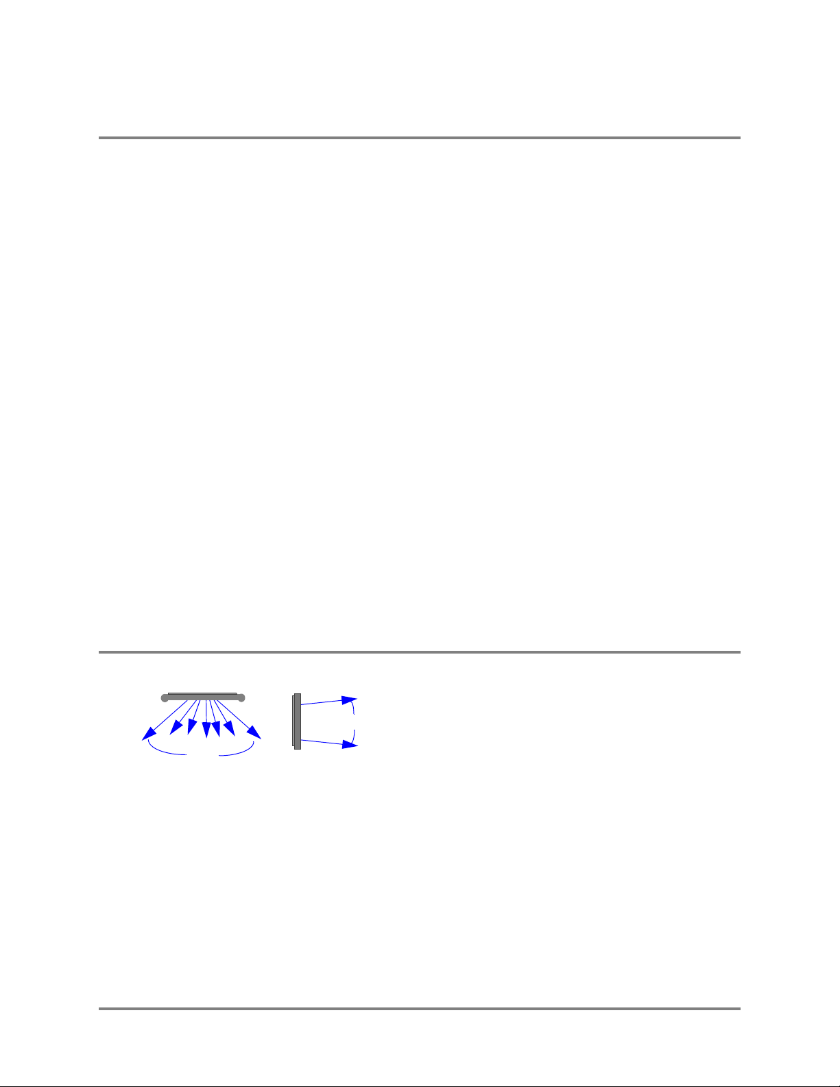
Top View
Side View
12
°
100°
reflect signals inside the antenna’s defined pattern, often providing Wi-Fi operation outside of
line-of-sight conditions.
The Wi-Fi Switch’s antenna is designed to transmit and
receive signals primarily in a 100° pattern from side to
side (horizontally), and at a 12° pattern vertically.
However, Wi-Fi operation outside of this pattern is
typically available, especially near the Wi-Fi Switch.
Also, various surfaces in the indoor environment can
4 Vivato 2.4 GHz Wi-Fi Switch User Guide
Indoor Wi-Fi Switch Installation
Where to Mount The Indoor Wi-Fi Switch
Where you mount the Wi-Fi Switch depends on a number of factors, including:
• room shape and dimensions
• ceiling height
• availability of mains (AC) power and LAN connections
• wall construction materials and other obstructions (elevator shafts, metal panels, water pipes...)
• interfering signal sources (microwave ovens, 2.4 GHz cordless phones, other 802.11b devices...)
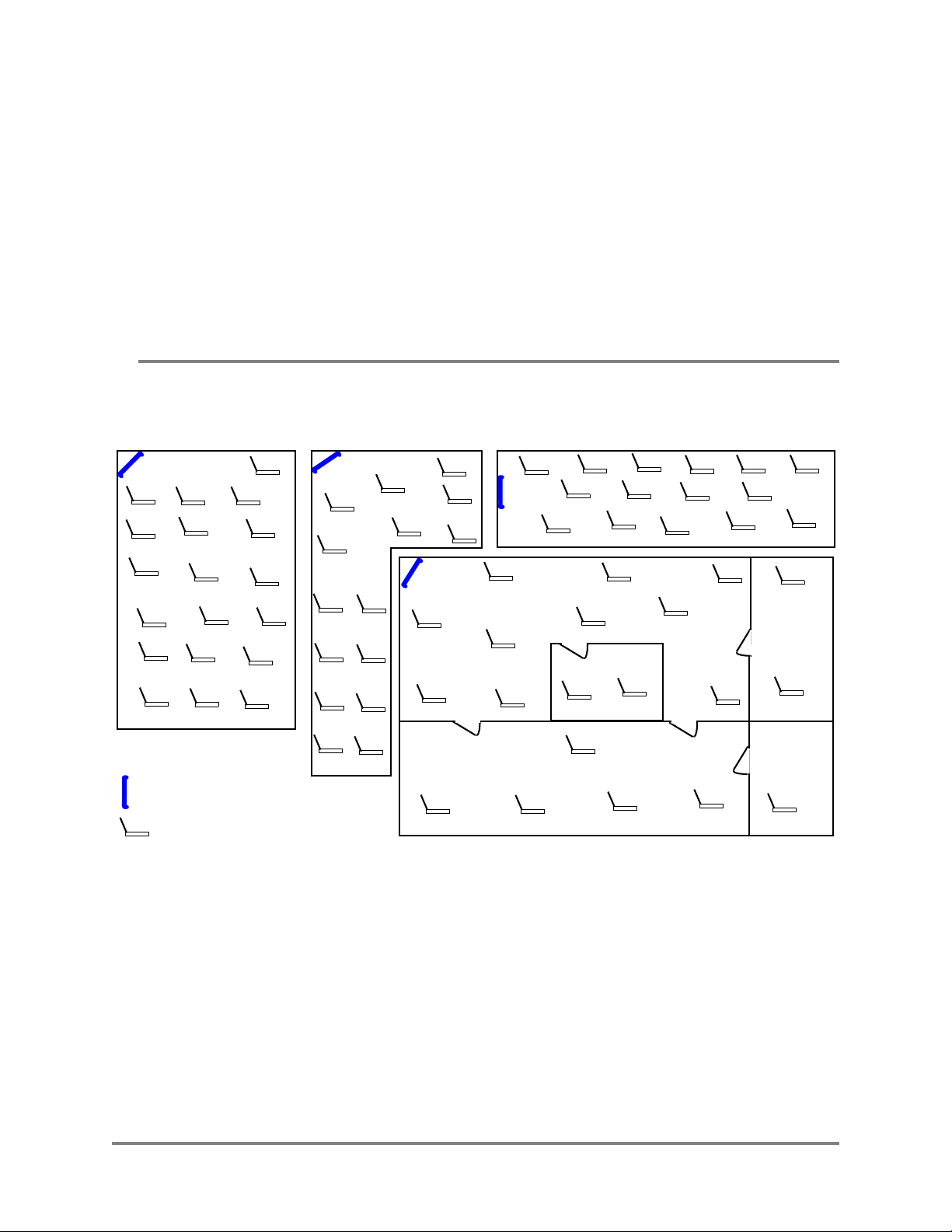
Analyzing Room Shape for Best Coverage
In general, position the Wi-Fi Switch to provide the greatest line of sight access to the farthest
clients. Mounting the switch in the corner of an open room is often the best solution. In an elongated
rectangular room, mounting the Wi-Fi Switch flat against an end wall works well.
Vivato Wi-Fi Switch
Wi-Fi Clients
Vivato 2.4 GHz Wi-Fi Switch User Guide 5
Indoor Wi-Fi Switch Installation
Where to Mount The Indoor Wi-Fi Switch
Ceiling Height Considerations
You should mount the Wi-Fi Switch several feet above any cubicle walls or other nearby
obstructions. In a typical single-floor indoor environment with 9 to 12 ft (about 3 to 4 m) high
ceilings, mount the top edge of the Wi-Fi Switch close to the ceiling.
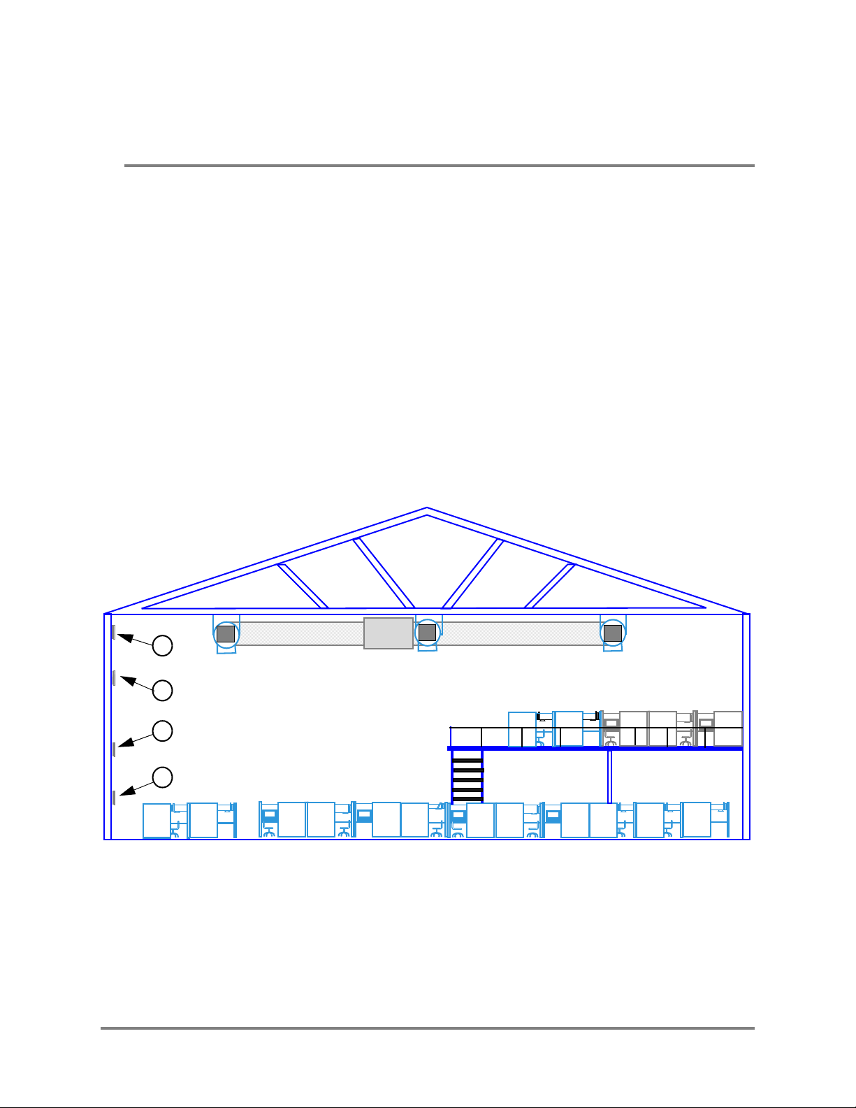
The figure below shows an open office where the ceiling is very high, and where clients are on more
than one level. Location #4 is too low, being at the same height as office cubicle walls, much of the
signal is blocked and the Switch’s antenna pattern is not allowed to be fully focused (see
Minimizing Obstructions below).
Location #3 is high enough to provide coverage to both levels of cubicles in this building. However,
if the building were much longer or higher, locating the Wi-Fi Switch higher would be beneficial.
Location #2 positions the Wi-FI Switch higher on the wall to maximize coverage on distant clients,
while still providing good coverage to the nearest clients below it. This is often the best location
where Wi-Fi operation is being provided to distant clients or where more than one building floor is
being served.
Location #1, while providing some Wi-Fi operation to close clients, is poorly positioned because
metallic air ducts are situated a short distance from, and directly in front of, the Wi-Fi Switch.
1
2
3
4
Figure 1—Location 2 Optimizes Wi-Fi Coverage
6 Vivato 2.4 GHz Wi-Fi Switch User Guide
Minimizing Obstructions
Indoor Wi-Fi Switch Installation
Where to Mount The Indoor Wi-Fi Switch
Important
All materials provide some resistance to the wireless signal. However, very dense materials, such
as metals and windows, degrade the signal more than less dense materials, such as cloth cubicle
panels. To maximize the Wi-Fi coverage area and signal strength, position the Wi-Fi Switch where
there are no obstructions directly in front of it.
The Wi-Fi Switch’s signal does go through typical gypsum (drywall) wall materials (with some
signal loss) to provide Wi-Fi connectivity in conference rooms or other enclosed areas. However,
metal duct work inside the walls, or machinery or appliances directly in the signal’s path (heating,
ventilation, air conditioning, electrical pannels...etc) cause additional decreases in the signal
strength and may reduce the data rate to less than the full 11 Mbps.
The Wi-Fi Switch’s antenna combines the signals of several elements into focused,
low power antenna patterns. These patterns are fully focused at a distance of
approximately 16 feet (about 5 meters) in front of the Wi-Fi Switch. To provide
maximum coverage, it is important that objects are not placed closer than this
distance directly in front of the Wi-Fi Switch. For example, do not position the Wi-Fi
Switch facing directly against a wall, window, or other surface to try to provide
coverage on the other side of that object.
Interfering Signal Sources
IEEE 802.11b devices share the same unlicensed frequency band as other common devices, such as
some radio frequency identification (RFID) systems, some cordless telephones, and microwave
ovens. These devices produce radio frequency (RF) energy that can interfere with the Wi-Fi
Switch’s signal. Whenever possible, you should eliminate or minimize the use of these devices
within the switch’s operating area in order to maximize Wi-Fi data rates.
The Vivato Wi-Fi Switch uses the same frequencies as conventional access points (APs). To see if
an access point is interfering, use the rogue access point detector (RAPD). See "Rogue Access
Point Detection (RAPD) and Notification" on page 83.
Environmental Considerations For Indoor Use
The following environmental specifications must be adhered to when mounting the Vivato 2.4 GHz
Indoor Wi-Fi Switch:
• Operating temperature range: 32° to 122° F (0° to 50° C)
• Humidity: 10 % to 90% (non-condensing)
Vivato 2.4 GHz Wi-Fi Switch User Guide 7
Indoor Wi-Fi Switch Installation
Assembling the Wi-Fi Switch
Assembling the Wi-Fi Switch
The top and bottom rails and end caps must be installed before mounting the Wi-Fi Switch. The fabric
dress cover can be attached before or after mounting the Switch.
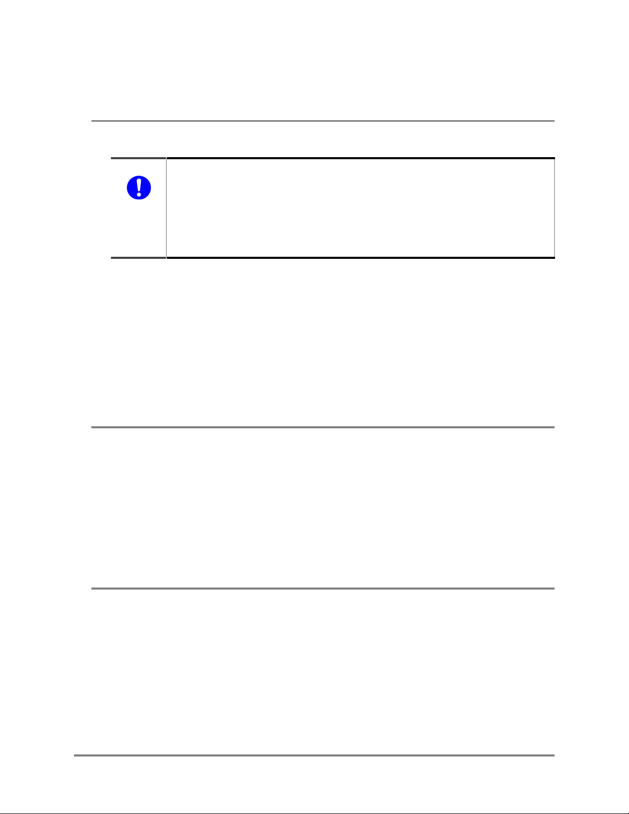
Attaching the Top and Bottom Rails
The top and bottom rails provide the mounting points for the end caps, Velcro® attachment area for
the fabric cover, and channels for routing power and data cables. As shown below, the upper and
lower rails have different part numbers and are not interchangeable.
Each rail is attached using five (5) screws that are pre-installed in the Wi-Fi Switch. To install the
rails, remove the screws indicated below (#2 phillips), position the rails as shown, and replace the
screws, tightening them to 10 in-lbs. (1.13 Nm).
Top rail: PN 610-00546
Remove and replace these screws to mount this rail.
Remove and replace these screws to mount this rail.
Bottom rail: PN 610-00547
Power and Data Connectors
8 Vivato 2.4 GHz Wi-Fi Switch User Guide
Indoor Wi-Fi Switch Installation
Assembling the Wi-Fi Switch
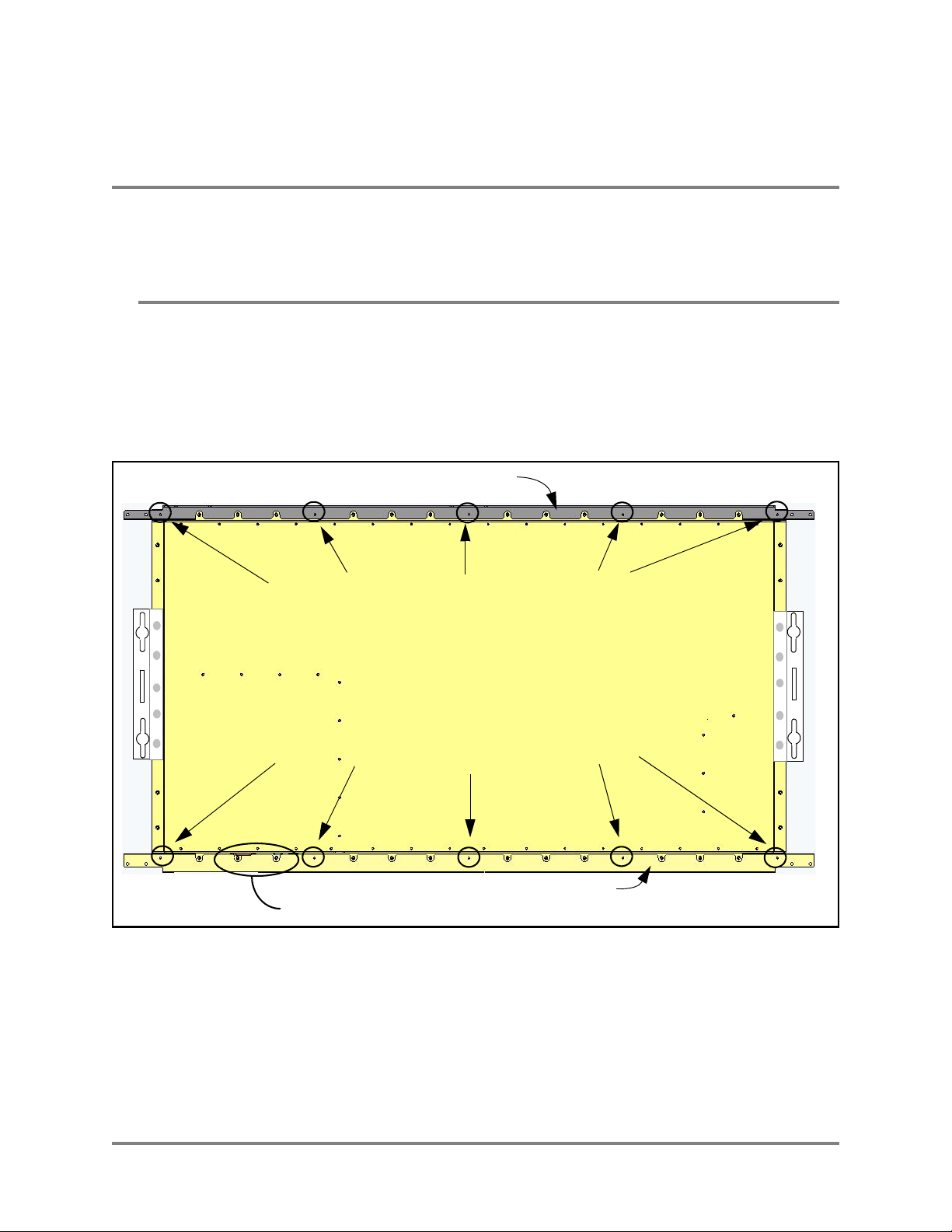
Attaching the End Caps
The end caps must be installed before mounting the Wi-Fi Switch. Each cap is attached using four
(4) of the provided self-tapping screws on each end (as shown below). Turn each screw in until the
end cap is just held against the rail.
Wi-Fi Switch Rear Panel
End Cap
Figure 2—Installing the End Caps
Attaching the Fabric Cover
The fabric cover is attached to the Wi-Fi Switch using simple Velcro® strips. Position the cover over
the Wi-Fi Switch’s front panel and carefully press the fabric onto the corresponding velcro strips on
the Switch. Be sure to orient the connector cut-outs in the Wi-Fi Switch’s bottom flange with the
openings in the fabric cover.
End Cap
Vivato 2.4 GHz Wi-Fi Switch User Guide 9
Indoor Wi-Fi Switch Installation
Cable Routing to the Wi-Fi Switch
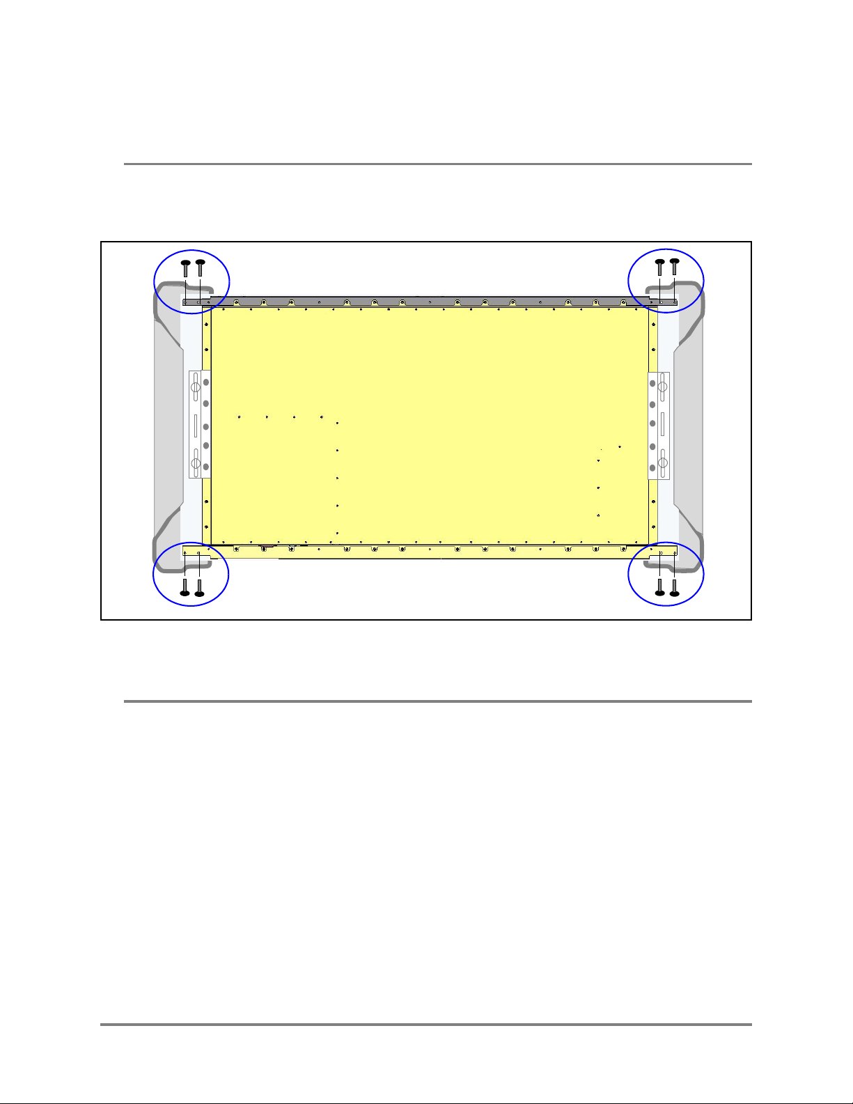
Cable Routing to the Wi-Fi Switch
Cabling for power and data connections for a wall-mounted Wi-Fi Switch can be routed above or below
the Switch, through a center opening or through an offset opening.
Note: When routing cables through the top of the Wi-Fi Switch during the flush mount
installation, be sure to route the cables before mounting the Switch. The optional corner
mounts provides enough room behind the Wi-Fi Switch to allow cable routing after
installation.
CAUTION —Do not mount the Wi-Fi Switch upside down to change the orientation of the connections!
When using the upper openings, be sure
to route the cables before mounting the
Switch on the wall with the flush mounts.
Connectors
Power|LAN|RS-232
Figure 3—Available Cable Routing Methods
Wi-Fi Switch Rear Panel
Power Cord
LAN Cable
10 Vivato 2.4 GHz Wi-Fi Switch User Guide
Indoor Wi-Fi Switch Installation
Mounting the Wi-Fi Switch
Mounting the Wi-Fi Switch
Mounting brackets are provided for flat wall installation. You can also order an optional corner mount
bracket.
Four metal hollow wall anchors are provided for use with 5/8” commercial gypsum board (drywall).
When installed and used properly, these fasteners can easily support the weight of the Wi-Fi Switch.
When mounting against brick, the use of lead anchors, or some other expanding fastener system that will
not loosen in the bricks over time, is recommended.
Warning
The Vivato Wi-Fi Switch must be fastened to a surface that can support its weight without
compromising safety in the event of strong vibration (such as an earthquake) or from physical
impact. Mounting the Vivato Wi-Fi Switch in a manner that provides continued safety for
persons and property is the sole responsibility of the installer. Do not mount the Wi-Fi Switch
using brackets other than those approved by Vivato, Inc.
The installer of the Vivato Wi-Fi Switch is also responsible for complying with any applicable
building and wiring regulations or codes.
Caution
The Wi-Fi Switch is specifically designed to be operated with the power and data
connectors pointing down. Do not mount the Wi-Fi Switch upside down to re-orient
the connectors.
Mounting Weight Considerations
The total weight of the installed Wi-Fi Switch, including the top and bottom dress rails, end caps,
and dress cover, is 40.5 lbs (18.4 kg).
Mounting The Wi-Fi Switch on a Wall (Flush Mount)
The following instructions show how to mount the Wi-Fi Switch flush against a wall by installing
the supplied mounting brackets to the wall and then attaching the Wi-Fi Switch to those brackets.
1 Position one of the brackets a minimum of 7.5 in. (19 cm) below the ceiling. Using a level,
make sure that the bracket is plumb (straight up and down) and that the notch in the side of
the bracket faces outward from where the other bracket will be mounted. See "Installing the
Flush Mount Wall Brackets" on page 12.
2 Mark the position for the supplied hollow wall anchors through the horizontal slots at the top
and bottom of the bracket. Put the marks slightly in from the center of the notches.
3 Carefully drill a 7/16” hole for each anchor, making sure to keep the drill centered. (It may
be easier to start with a 1/8” bit, and then drill again using the 7/16” bit.)
4 Insert the anchors into the 7/16” holes, and lightly tap on each anchor to seat it against the
wall. See "Installing the Wall Bracket Using the Hollow Wall Anchors" on page 12.
Vivato 2.4 GHz Wi-Fi Switch User Guide 11
Indoor Wi-Fi Switch Installation
Mounting the Wi-Fi Switch
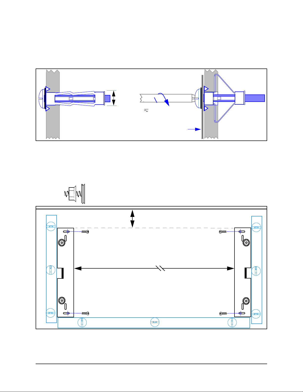
5 Remove the anchor screws, and thread them through the wall bracket and into the anchors
until the screw heads are flush against the bracket. Tighten the screws an additional 10 turns
to seat the anchors - do not over-tighten. Verify that the bracket is plumb and adjust as
necessary.
Figure 4—Installing the Wall Bracket Using the Hollow Wall Anchors
6 Mount the second bracket so that it is level with the first bracket, and is spaced exactly 40.5
in. (102.9 cm) apart from the first bracket at the inside edges.
7/16”
10 turns
Wall Bracket
7 Thread the supplied flange nuts out about half way on the bracket mounting studs.
Ceiling
≥7.5 in. (19 cm)
40.5 in. (102.9 cm)
Level
Level
Level
Figure 5—Installing the Flush Mount Wall Brackets
12 Vivato 2.4 GHz Wi-Fi Switch User Guide
Indoor Wi-Fi Switch Installation
Mounting the Wi-Fi Switch
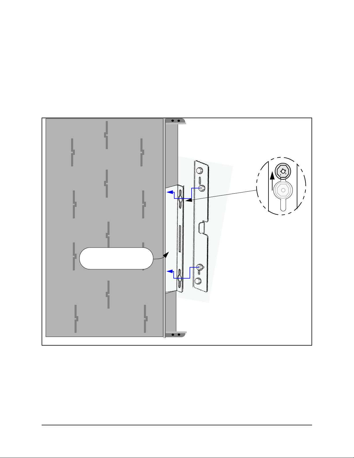
8 This step should be performed with two people supporting the Wi-Fi Switch!
With its connectors and power switch towards the floor, position the Wi-Fi Switch so that the
holes in its pre-installed brackets fit over the flange nuts on the wall brackets. See Figure 6—
Mounting the Wi-Fi Switch to the Flush Mount Wall Brackets.
9 Slide the Wi-Fi Switch down fully into the slots in the brackets.
10 Carefully squeeze the end caps in to expose the flange nuts, and tighten the nuts using a 3/8”
open end wrench.
(End cap not shown)
Pre-installed bracket
on the Wi-Fi Switch.
Figure 6—Mounting the Wi-Fi Switch to the Flush Mount Wall Brackets
Vivato 2.4 GHz Wi-Fi Switch User Guide 13
Indoor Wi-Fi Switch Installation
Mounting the Wi-Fi Switch
Mounting the Wi-Fi Switch Using the Optional Corner Mount Kit
Follow these steps to mount the Wi-Fi Switch in a corner using the optional corner mount kit.
Locating the bracket mounting holes and mounting the Wi-Fi Switch on the bracket is best
performed with two people!
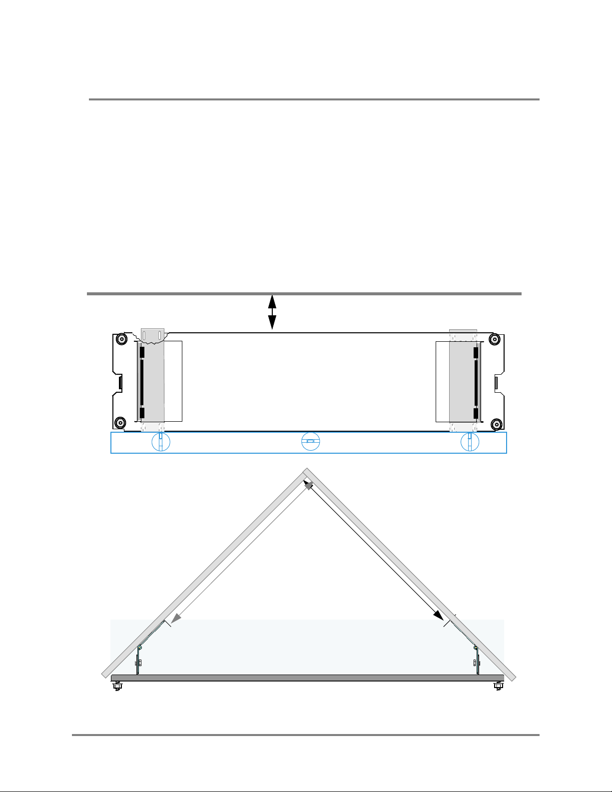
1 Position the bracket in the corner, a minimum of 9 in. (23 cm) below the ceiling. When
positioned squarely between the walls, the distance from the corner to the inside edge of the
hinged mounting plates is 22 7/16 in. (57 cm). See Figure 7— Installing the Corner Mount
Bracket.
2 While holding the bracket in place, scribe a mark through each of the four mounting holes
in both hinged mounting plates.
3 Using the scribe marks as a guide, install anchors or other reinforcements as necessary for
your fasteners.
Ceiling
≥9 in. (23 cm)
22 7/16
in.
Level
c
(57
Front View
m)
Top View
2
2
7
/
1
6
i
n
.
(
5
7
c
m
)
Figure 7—Installing the Corner Mount Bracket
14 Vivato 2.4 GHz Wi-Fi Switch User Guide
 Loading...