

USER MANUAL
GIOVE AC5


Index
1 Important Safety Instructions...........................................................................................................2
2 Product Overview.............................................................................................................................3
2.1 Specifications............................................................................................................................4
3 Package Contents..............................................................................................................................5
4 Functions and Configurations...........................................................................................................5
4.1 Electrical Connection................................................................................................................5
4.1.1 Connection single module.................................................................................................5
4.1.2 Cascading Connection.......................................................................................................6
4.2 User Menu.................................................................................................................................7
4.2.1 Changing Device ID..........................................................................................................7
4.2.2 Changing the Status of Contacts.......................................................................................7
4.2.3 Changing View Contacts...................................................................................................7
4.2.4 Change Communication Mode.........................................................................................8
4.3 Web Server................................................................................................................................9
4.3.1 State...................................................................................................................................9
4.3.2 Configuration Local IP....................................................................................................10
4.3.3 Connection Configuration...............................................................................................11
4.3.4 Control Contacts.............................................................................................................12
4.3.5 System Configuration.....................................................................................................13
4.3.6 Restart.............................................................................................................................14
5 Communication Protocols..............................................................................................................15
5.1 Standard Protocol AC5...........................................................................................................15
5.1.1 Port Settings....................................................................................................................15
5.1.2 ASCII String Description................................................................................................15
5.1.3 Command Example ASCII String...................................................................................15
5.1.4 Response Example ASCII String....................................................................................15
5.2 Protocol ModBus RTU...........................................................................................................16
6 Technical Specifications.................................................................................................................17
1 GIOVE AC5

1 IMPORTANT SAFETY INSTRUCTIONS
This device is designed and manufactured to assure personal safety. Improper use can result in
electric shock or fire hazard. The safeguards incorporated into this unit will protect you if you
observe the following procedures for installation, use, and servicing.
• Follow all warnings and instructions marked on the product.
• Unplug this product from the wall outlet before cleaning. Do not use liquid cleaners or
aerosol cleaners. Use a damp cloth for cleaning.
• Do not use this product near any liquids.
• Do not place this product on an unstable surface. The product may fall, causing serious
damage to the product.
• Do not drop the product.
• Do not block the slots and openings on the top and bottom of the chassis; to ensure proper
ventilation and reliable operation of the product and to protect it from overheating, these
openings must not be blocked or covered.
• Operate this product only from the type of power indicated on the marking label.
• Do not allow anything to rest on the power cord. Do not locate this product where persons
will walk on the cord.
• Never push objects of any kind into this product through the chassis slots as they may touch
dangerous voltage points or short out parts that could result in a fire or electric shock.
• Unplug this product from the wall outlet and refer servicing to qualified service personnel
under the following conditions:
◦ When the power cord or plug is damaged or frayed.
◦ If liquid has been spilled on the product.
◦ If the product has been exposed to rain or water.
◦ If the product does not operate normally when the operating instructions are followed.
Adjust only those controls that are covered by the operating instructions since improper
adjustment may result in damage and require extensive work by a qualified technician to
the product to normal condition.
◦ If the product has been dropped or the chassis has been damaged.
◦ If the product exhibits a distinct change in performance, contact Vivaldi Customer
Support.
Vivaldi S.R.L. it reserves the right to update this document at any time without notice.
GIOVE AC5 2

2 PRODUCT OVERVIEW
The Giove AC5 is a device for remote management with five contacts in deviation with europlug
terminal (Max 5A).
By using the RJ45 port is possible to connect the Giove AC5 to the local network, and manage it
with Vivaldi iControl or a home automation supervisor.
It includes an integrated web server, where you can manually control the contacts and manage
settings.
At the first device connected to the LAN you can be connected, in cascade, four other device using
the europlug connector.
3 GIOVE AC5
2.1 SPECIFICATIONS
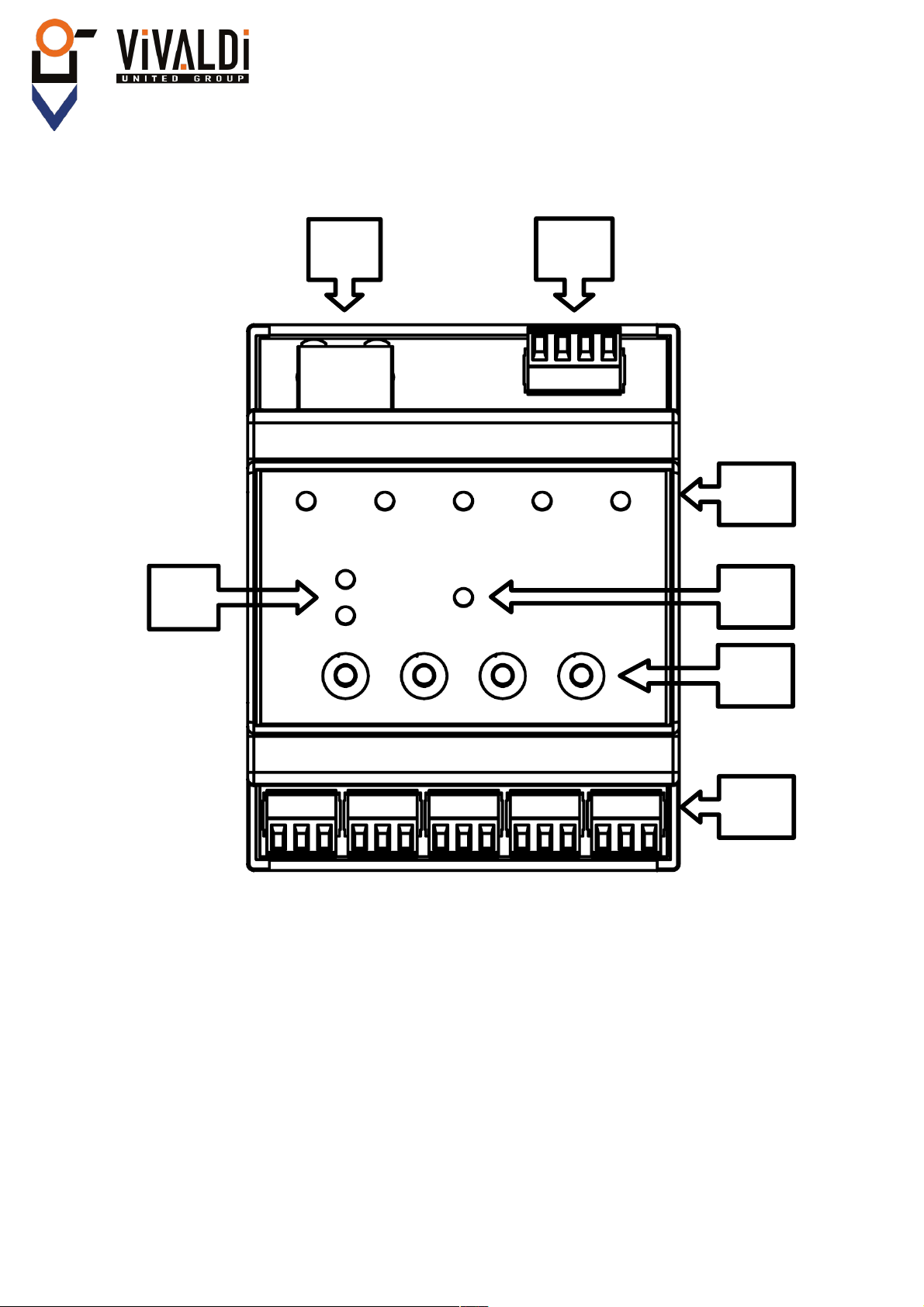
A) Status LED of the Ethernet network: LINK = Green, DATA = Yellow;
B) RJ45 connector, Ethernet connection 10/100Mbps;
C) Europlug connector, | B | A | - | + |, for power supply and RS485 connection with other
devices Giove AC5;
D) Five multicolour LED matching to the relay, used to display relay status;
E) Power ON LED, indicates that the device is turned on;
F) Four button to device management;
G) Five europlug connector 3-way for five contacts in deviation, | NO | COM | NC |.
GIOVE AC5 4
B
C
D
E
F
G
A
Figure 1

3 PACKAGE CONTENTS
• Giove AC5
• Instruction
4 FUNCTIONS AND CONFIGURATIONS
4.1 ELECTRICAL CONNECTION
4.1.1 Connection single module
For proper operation of the device you need to feed it through the connector (Figure 1-C) from 12 to
24 Vdc. Attention to the polarity!
For communication, connecting the LAN to the RJ45 connector (Figure 1-B), using a CAT5e cable.
To contacts can be connected a maximum load of 5A(NO) and 3A(NC).
5 GIOVE AC5

4.1.2 Cascading Connection
For the cascade connection, plug the europlug connector 4-way in parallel (Figure 1-C), and
connect the LAN network cable only to the first device.
It will be necessary then to set a unique ID in the devices, from 1 to 5. (See Section 4.2)
The power supply must be properly sized for 5 devices, it recommends 1.5A 24Vdc.
GIOVE AC5 6

4.2 USER MENU
4.2.1 Changing Device ID
You can connect multiple cascaded devices (Max. 5),ID identifies the unique number of the Giove
AC5 present in the Rs485 Bus.
To change this parameter from the front panel, holding the button P1 (Figure 2) until the LED 1
become red.
You can move within this menu with the P2 and P3 keys, for the ID change you typically carry the
P3 button until the LED 5 and confirm with the button P1.
After confirming the current ID is displayed in green, to change it is sufficient to move from 1 to 5
with the P2 and P3 button, choose the number of ID and confirm with the P1 button.
Protocol Standard AC5:
• LED 1-5 = ID 0-4
Protocol Mod-Bus:
• LED 1-5 = ID 11-15
To confirm the selection , there will be a quick flashing of the five LEDs in red.
To quit the menu either wait or press the button P4.
4.2.2 Changing the Status of Contacts
To perform a manual relay control, you must hold the P1 button until the LED 1 is red.
You can move within this menu with the P2 and P3 buttons, to change the state of the contacts you
select LED 1 and confirm with P1 button.
With the P2 and P3 buttons select the contact, then press the P1 button to change the contact status.
To quit the menu either wait or press the button P4.
4.2.3 Changing View Contacts
When the device is in standby mode you can view the status of contacts.
There are two display types:
1. Active contact, LED is green. Disabled contact, LED is off.
2. Active contact, LED is off. Disabled contact, LED is green.
To switch between them, holding the P2 button in standby mode.
7 GIOVE AC5
Figure 2

4.2.4 Change Communication Mode
You can communicate with Giove AC5 with the standard protocol, either Mod-Bus RTU. To switch
from one mode to another, you must enter the menu by holding down the P1 button and select,
using the P2 and P3 buttons, the LED 4.
Confirming with the P1 button you enter the menu of choice between:
• LED 1 = Protocol Mod-Bus.
• LED 2 = Protocol Standard AC5.
Press P1 to confirm your choice, it will be a quick flashing of the LED for confirmation.
Once configured the protocol, you must change the IP configuration via the web page (See Section
4.3.3).
When using the Mod-Bus protocol, set to “TCP SERVER” the voice “mode of operation”.
Press the SAVE button before leaving the page.
GIOVE AC5 8

4.3 WEB SERVER
The device has a built-in WEB SERVER, for configuration and management of contacts .
The default IP address is 192.168.0.103, then, after have plug the device to the network, simply
open any Internet browser (Firefox, Chrome, Safari, etc...) and enter the Default IP address on the
address-bar.
The authentication window will open, then you can enter the default username and password:
• User: admin (default)
• Password: admin (default)
4.3.1 State
After entered the credentials will open the Home Page of the Giove AC5 (See Figure 3).
On the Status menu you can view the general status of the device.
9 GIOVE AC5
Figure 3

4.3.2 Configuration Local IP
On this page you can change the network parameters of the Giove AC5.
To save the changes made, click on the button Save.
GIOVE AC5 10
Figure 4

4.3.3 Connection Configuration
On this page you can configure the port and the communication protocol with the home automation
controller.
To save the changes made, click on the button Save.
11 GIOVE AC5
Figure 5

4.3.4 Control Contacts
On this page you can perform manual switching of one of the contacts and request information
about the firmware version and hardware of the Giove AC5.
In the drop-down list you can select the destination device ID, connected to the first Giove AC5, for
each is possible to run the switching of contacts.
N.B. IT WORKS ONLY WITH STANDARD PROTOCOL AC5
GIOVE AC5 12
Figure 6

4.3.5 System Configuration
On this page you can change the name of Giove AC5, the ports number of the web server, user
name and password.
To save the changes made, please click on the button Save.
13 GIOVE AC5
Figure 7

4.3.6 Restart
On this page you can restart the device remotely.
GIOVE AC5 14
Figure 8

5 COMMUNICATION PROTOCOLS
For managing the Giove AC5 combined with Vivaldi iControl +, or other home automation systems,
simply send the following command strings.
5.1 STANDARD PROTOCOL AC5
5.1.1 Port Settings
BAUD RATE 19200
DATA BITS 8
PARITY NONE
STOP BITS 1
5.1.2 ASCII String Description
Byte 0 Byte 1 Byte 2 Byte 3 Byte 4 Byte 5 Byte 6 Byte 7 Byte 8
Z 0-4 0-1 0-1 0-1 0-1 0-1 0 <CR>
Byte 0. ‘Z’ START BYTE;
Byte 1. From ‘0’ to ‘4’, is the ID number of the AC5 module;
Byte 2. Relay 1: 0 = Off 1 = On
Byte 3. Relay 2: 0 = Off 1 = On
Byte 4. Relay 3: 0 = Off 1 = On
Byte 5. Relay 4: 0 = Off 1 = On
Byte 6. Relay 5: 0 = Off 1 = On
Byte 7. Byte not used
Byte 8. <CR> String end (equivalent to 13 in decimal or 0x0D in hexadecimal)
5.1.3 Command Example ASCII String
Having 2 Giove AC5 connected , the string for turn On the RELAY 3 on device with ID 2 will be:
“Z1xx1xxx<CR>”
Not to change the status of the relays not interested you can place a neutral character like ‘x’.
In addition there are 3 types of BROADCAST command:
1. Power ON all contacts: “ZÿYYYYYY<CR>”
2. Power Off all contacts: “ZÿXXXXXX<CR>”
3. Custom Broadcast: “Zÿ100100”<CR>”(Example)
5.1.4 Response Example ASCII String
Having 2 Giove AC5 connected, the response string after sending the previous command will be:
“Z1001000”<CR>
15 GIOVE AC5

5.2 PROTOCOL MODBUS RTU
To communicate through the ModBus protocol you must write in the registers, as in the table:
Relay 1 registry 5 0=OFF, 1=ON
Relay 2 registry 6 0=OFF, 1=ON
Relay 3 registry 7 0=OFF, 1=ON
Relay 4 registry 8 0=OFF, 1=ON
Relay 5 registry 9 0=OFF, 1=ON
GIOVE AC5 16

6 TECHNICAL SPECIFICATIONS
Supply Voltage 12-24Vdc
Maximum Current 200mA
Maximum Current of contacts in deviation NO= 5A, NC=3A
Network Connection 10/100Mbps
17 GIOVE AC5

MU_A84_05/16_R90
Vivaldi S.R.L.
Administrative Headquarters
Via E. Fermi, 8 - Z. I. Est – 30020
Noventa di Piave (VE) Italy
tel. +39 0421 307825 fax +39 0421 307845
info@vivaldigroup.it www.vivaldigroup.it
www.vivaldigroup.it info@vivaldigroup.it
 Loading...