

Vivaldi GIADA213HPA Operative Manual
GIADA213HPA
OPERATIVE MANUAL
Please follow the instructions in this manual to get the best results from this product.
We also recommend that keep this manual handy for future reference.
GIADA213HPA OPERATIVE MANUAL A84-03/16 1
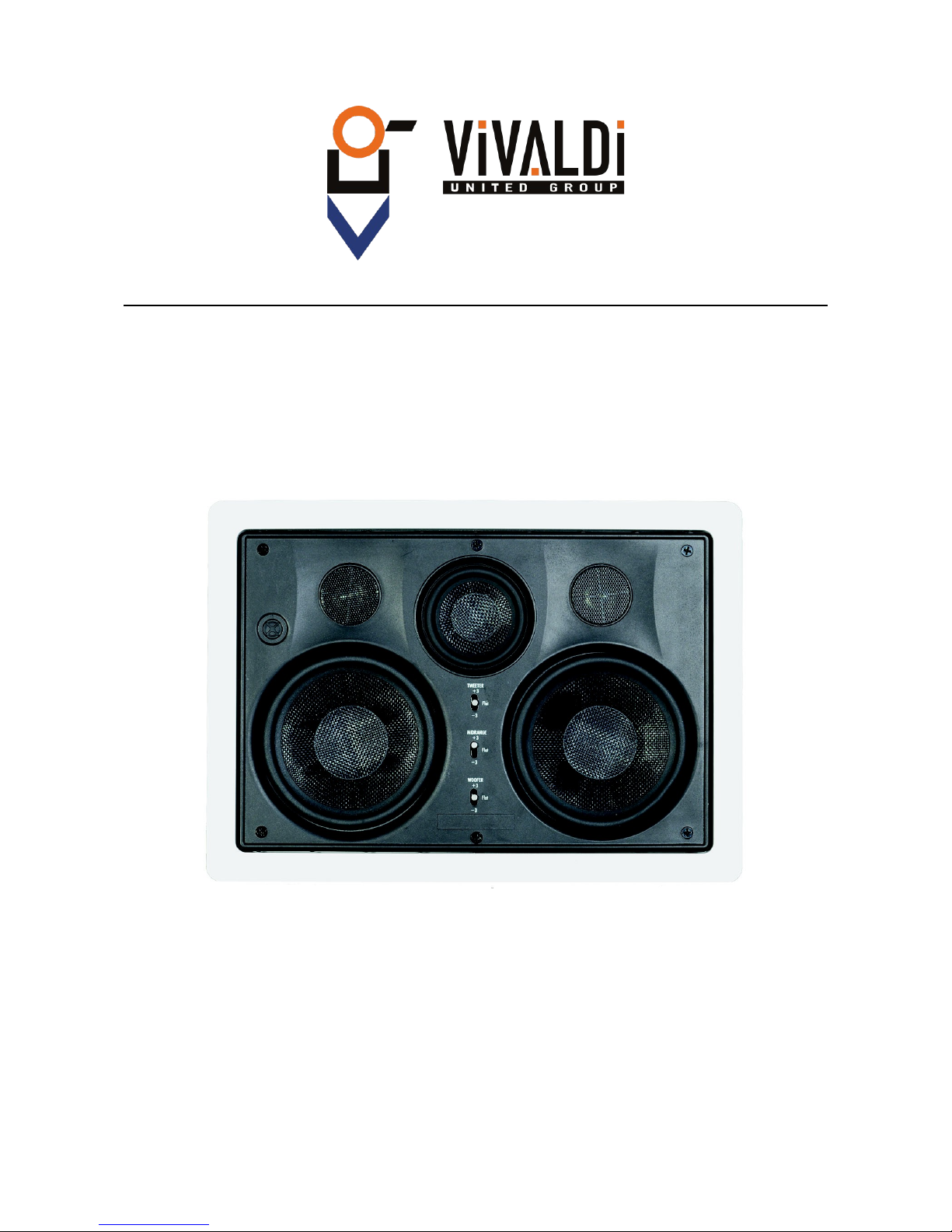
1. MECHANICAL INSTALLATION
For the installation of the speaker simply remove the 6 screws that support the
central part of the same.
Once isolated from the frame main body, it can be fixed to the wall simply by
screwing the 6 screws corresponding to the support hooks.
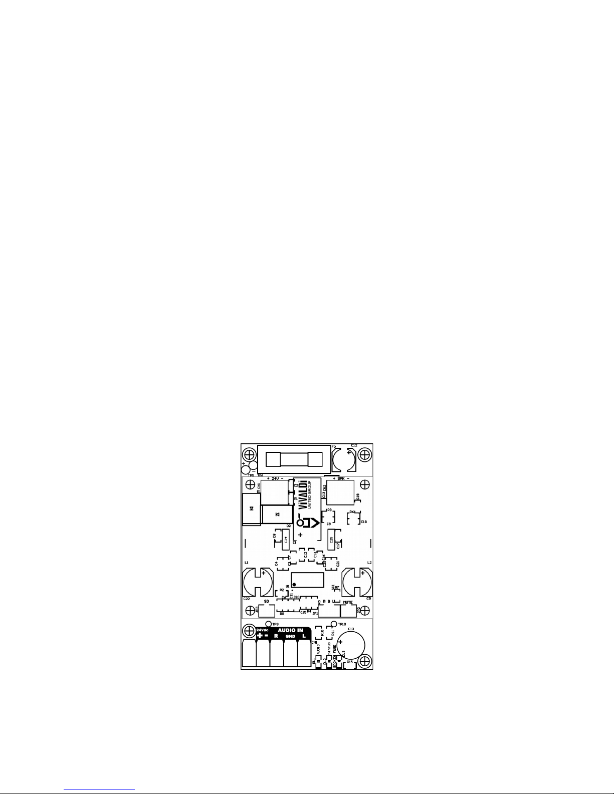
2. ELECTRICAL INSTALLATION
Inside the frame there is the audio amplifier, where will be connected
the following signals (show in Fig. 1):
+24Vdc= Positive power supply;
-24Vdc= Negative power supply;
R= Right channel;
Gnd= Shield audio cable;
L= Left channel;
The 2x0,75 mm cable, already connected, the SPK terminal must be connected to the
speaker respecting the polarity.
FIG. 1
GIADA213HPA OPERATIVE MANUAL A84-03/16 2
 Loading...