

Page 1
INSTALLATION, OPERATION, CONFIGURATION AND MAINTENANCE MANUAL
October/2019
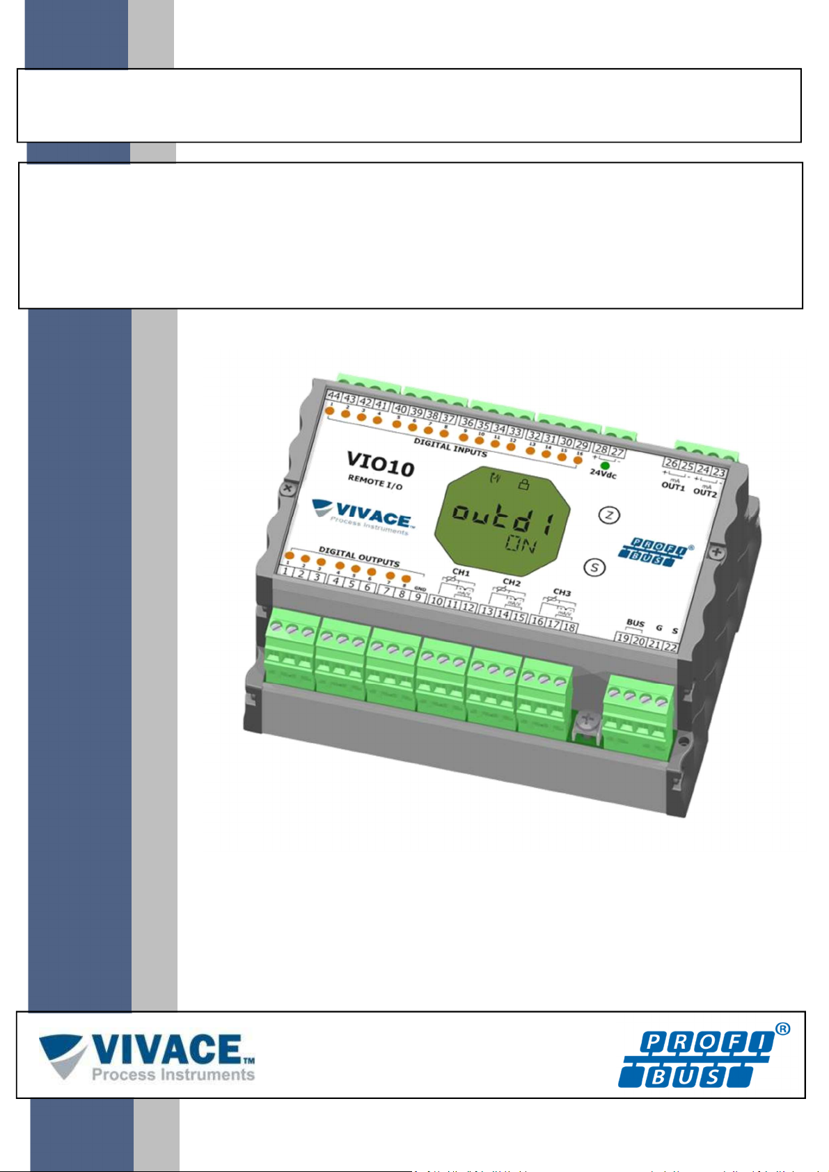
VIO10-P
PROFIBUS-PA REMOTE I/O
Page 2
VIO10-P PROFIBUS-PA REMOTE I/O INSTALLATION, OPERATION, CONFIGURATION AND MAINTENANCE MANUAL
______________________________________________________________________________________________________________________________
COPYRIGHT
All rights reserved, including translations, reprints, complete or partial reproduction of this
manual, patent concession or model register of use/project.
No part of this publication may be reproduced, copied, processed or transmitted on any manner
or any medium (photocopy, scanning, etc.) without the express permission of Vivace Process
Instruments Inc., not even for training or electronic systems.
PROFIBUS ® is a registered mark of PROFIBUS International.
NOTE
We have reviewed this manual with great care to maintain compliance with the hardware and
software versions described herein. However, due to the dynamic development and version upgrades,
the possibility of technical deviations cannot be ruled out. We cannot accept any responsibility for the
full compliance of this material.
Vivace reserves the right to, without notice, make modifications and improvements of any kind
in its products without incurring in any circumstances, the obligation to make those same modifications
to products sold previously.
The information in this manual is frequently updated. Therefore, when using a new product,
please check the latest version of the manual on the Internet through our website
www.vivaceinstruments.com, where it can be downloaded.
You customer is very important for us. We will always be grateful for any suggestions for
improvements as well as new ideas, which can be sent to the e-mail: [email protected]
preferably with the title "Suggestions".
2
Page 3

VIO10-P PROFIBUS-PA REMOTE I/O INSTALLATION, OPERATION, CONFIGURATION AND MAINTENANCE MANUAL
______________________________________________________________________________________________________________________________
SUMMARY
1 EQUIPMENT DESCRIPTION ................................................................................................................................. 7
1.1. BLOCK DIAGRAM ..................................................................................................................................... 7
2 INSTALLATION ..................................................................................................................................................... 9
2.1. MECHANICAL ASSEMBLY ....................................................................................................................... 9
2.2. ELECTRICAL CONNECTION .................................................................................................................. 10
2.3. CONNECTIONS ...................................................................................................................................... 10
2.4. PROFIBUS NETWORK CONNECTION ................................................................................................... 14
3 CONFIGURATION................................................................................................................................................ 15
3.1. LOCAL CONFIGURATION ...................................................................................................................... 15
3.2. JUMPER CONFIGURATION FOR LOCAL ADJUST AND WRITE PROTECTION ................................... 16
3.3. LIQUID CRYSTAL DISPLAY .................................................................................................................... 17
3.4. LOCAL ADJUST CONFIGURATION TREE ............................................................................................. 17
3.5. PROFIBUS PROGRAMMER ................................................................................................................... 18
3.6. PROFIBUS CONFIGURATOR PROGRAMMING TREE .......................................................................... 18
3.7. FDT/DTM CONFIGURATION .................................................................................................................. 21
3.8. CYCLIC CONFIGURATION ..................................................................................................................... 22
4 MAINTENANCE ................................................................................................................................................... 25
4.1. ASSEMBLY AND DISASSEMBLY PROCEDURES ................................................................................. 25
4.2. SPARE PARTS ........................................................................................................................................ 26
5 CERTIFICATION .................................................................................................................................................. 27
6 TECHNICAL CHARACTERISTICS ...................................................................................................................... 28
6.1. IDENTIFICATION .................................................................................................................................... 28
6.2. TECHNICAL SPECIFICATION ................................................................................................................ 29
6.3. TEMPERATURE SENSORS .................................................................................................................... 30
6.4. ORDERING CODE .................................................................................................................................. 31
7 WARRANTY ......................................................................................................................................................... 32
7.1
GENERAL CONDITIONS ........................................................................................................................ 32
7.2
WARRANTY PERIOD ............................................................................................................................. 32
APPENDIX .................................................................................................................................................................... 33
3
Page 4
VIO10-P PROFIBUS-PA REMOTE I/O INSTALLATION, OPERATION, CONFIGURATION AND MAINTENANCE MANUAL
______________________________________________________________________________________________________________________________
WARNING
It is extremely important that all the safety instructions, installation and operation in this manual
are followed faithfully. The manufacturer is not liable for damage or malfunction caused by improper
use of this equipment.
It is recommended to strictly following the rules and good practice relating to installation,
ensuring correct grounding, noise insulation and good quality cables and connections in order to
provide the best performance and durability to the equipment.
Special attention must be considered in relation to installations in hazardous areas, where
applicable.
SAFETY PROCEDURES
• Appoint only skilled people, trained with process and equipment;
• Install equipment only in operation compatible areas, with the proper connections and
protections;
• Use proper safety equipment for any handling device in field;
• Turn area power off before equipment installation.
SYMBOLOGY
Caution - indicates risk or error source
Important Information
General or Specific Risk
Electric Shock Danger
4
Page 5
VIO10-P PROFIBUS-PA REMOTE I/O INSTALLATION, OPERATION, CONFIGURATION AND MAINTENANCE MANUAL
______________________________________________________________________________________________________________________________
1
GENERAL INFORMATION
Vivace Process Instruments ensures the operation of this equipment, according to the
descriptions contained in its manual, as well as technical characteristics, not
guaranteeing its full performance in particular applications.
The operator of this equipment is responsible for observing all aspects of safety and
prevention of accidents applicable during the execution of the tasks in this manual.
Failures that might occur in the system, causing damage to property or injury to
persons, shall additionally be prevented by external means to a safe outlet for the
system.
This equipment must be used only for the purposes and methods proposed in this
manual.
DATA SAVING
Whenever static data is changed via configuration, LCD will display icon, which will
be blinking until the save process is complete.
If user wishes to shut down the equipment, he must wait for the process to be finished.
If the equipment is shut down during saving process, a default will be performed, setting
default values in device parameters and the user must subsequently check and configure
those parameters according to his needs.
ERROR ON SAVING DATA
If a data execution or saving operation was incorrectly performed, message "BlkEr" will
be displayed when the equipment is powered up.
In this case, user must perform factory initialization using two magnetic tool units as
described below. Application-specific settings should be performed again after this
procedure (except for the physical address and the "GSD Identifier Number Selector"
parameter).
- With the equipment off, access "Z" and "S" holes of local adjustment, located under the
equipment nameplate;
- Insert one of the tools inside "Z" hole and the other inside "S" hole;
- Energize the equipment and keep both magnetic tool units until icon is displayed;
- Do not turn off power while icon is displayed. If this happens, restart the procedure.
5
Page 6

VIO10-P PROFIBUS-PA REMOTE I/O INSTALLATION, OPERATION, CONFIGURATION AND MAINTENANCE MANUAL
______________________________________________________________________________________________________________________________
SIMATIC PDM CONFIGURATION
When using SIMATIC PDM tool for configuration/parameterization of this equipment, do
not use "Download to Device" option. This function could incorrectly configure the
equipment.
It is recommended for user to use "Download to PG/PC" option, to read the equipment
parameters and then access the "Menu Device" option, where one can find specific
menus for transducers, functional and LCD blocks, plus calibration, maintenance, factory
etc. According to each menu, user will then be able to change the parameter or function
as desired, in a fast and direct form.
6
Page 7
VIO10-P PROFIBUS-PA REMOTE I/O INSTALLATION, OPERATION, CONFIGURATION AND MAINTENANCE MANUAL
______________________________________________________________________________________________________________________________
1 EQUIPMENT DESCRIPTION
VIO10-P remote I/O is a member of Vivace Process Instruments Profibus-PA family, designed for
field installation or DIN rail panel.
The equipment is powered by a voltage of 9 to 32 Vdc, offers 16 inputs and 8 open-collector discrete
outputs, plus 3 inputs for two or three-wire temperature sensors (several sensor types such as
thermocouples and RTDs), as well as voltage signals (0 - 5 Vdc) or current (4 - 20 mA), configured by the
user. In addition, it offers two analog 4 - 20 mA outputs or open-collector for actuation, according to user
settings.
Through a Profibus-PA configurator, user can configure the remote I/O parameters as well as the
input and output channels, check calibrations, diagnostics and monitoring. In addition, it is possible to
configure VIO10-P via local adjustment using a magnetic screwdriver.
VIO10-P is connected to the Profibus-DP network via a DP/PA coupler, using a pair of twisted and
shielded wires. Profibus-PA technology allows the interconnection of several equipment in a single network,
allowing the construction of large control systems. VIO10-P works with the concept of functional blocks such
as Discrete Input and Output, Analog Input and Output, and Transducer.
Prioritizing its high performance and robustness, VIO10-P was designed with the latest electronics
and materials technologies, ensuring long-term reliability for systems of any scale.
1.1. BLOCK DIAGRAM
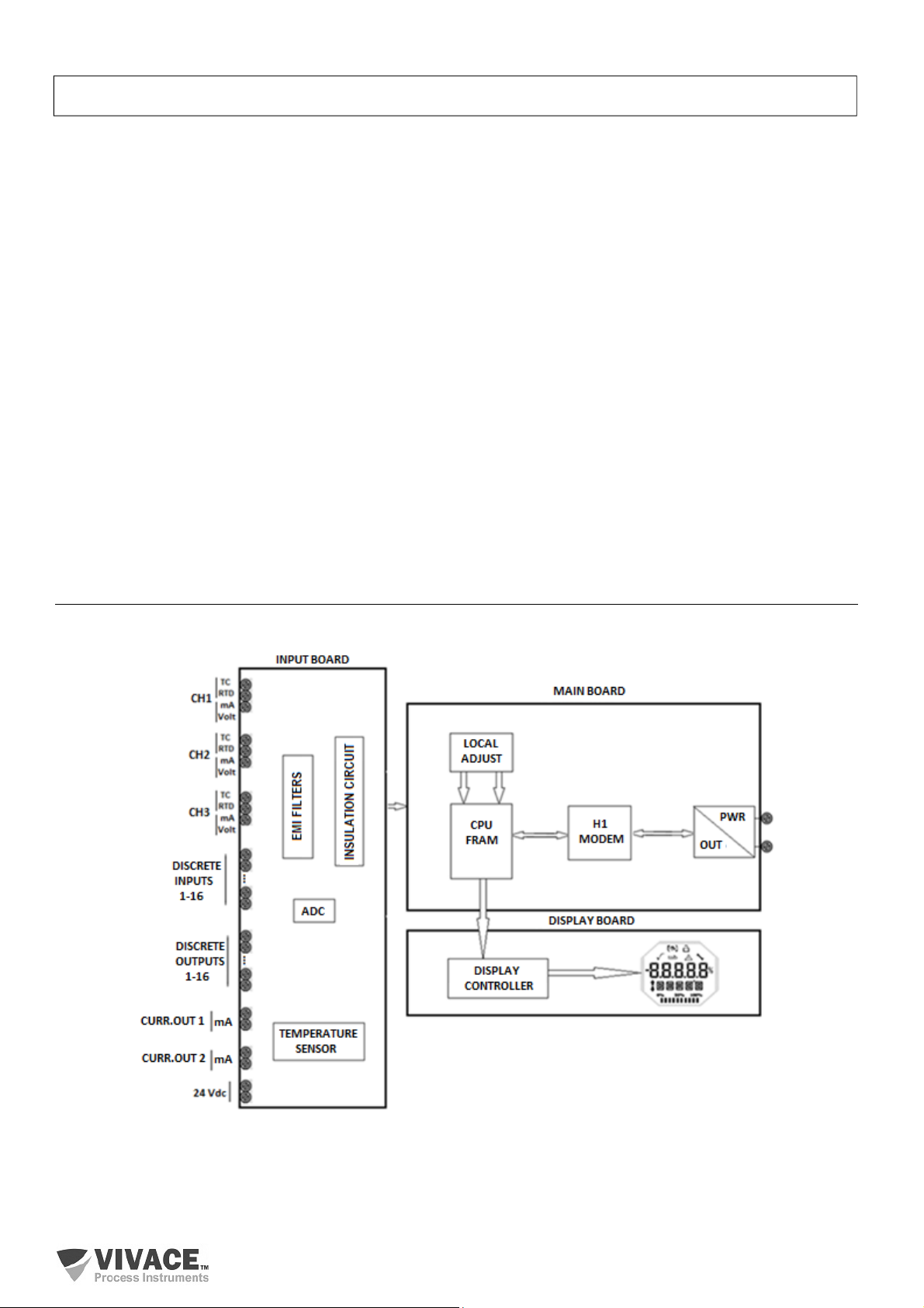
The modularization for VIO10-P componentes is described in the following block diagram.
Figure 1.1 – Block diagram for VIO10-P.
The signals from the temperature sensors or 4-20 mA inputs pass through the RF filter and follow to
the ADC converter, where they are converted into digital values. These values are converted to temperature
or current, according to the selected channel. The 4-20 mA outputs are generated according to user settings.
7
Page 8
VIO10-P PROFIBUS-PA REMOTE I/O INSTALLATION, OPERATION, CONFIGURATION AND MAINTENANCE MANUAL
NOT
E
______________________________________________________________________________________________________________________________
The sensor signals are galvanically isolated from the power supply, but are not insulated from each
other.
Digital inputs and outputs have latches that store their logic states. They are isolated, guaranteeing
the integration of the signals. The outputs use open-collector NPN transistors. User must work with relays,
solenoids and other loads DCs with maximum current of 0.5 A per output. All outputs share the same ground
and are isolated from each other, as well as from Profibus-PA network. The digital inputs and outputs share
the same DC source.
The H1 Modem Block interfaces the microcontroller signals with the Profibus-PA network to which
the equipment is connected.
The display board has the controller module responsible for adapting the messages to be displayed
on the LCD.
Finally, the microcontroller block can be related to the brain of the equipment, where all the time
controls, communication control, plus routines common to the equipment such as configuration, calibration
and monitoring take place.
The sensor signals are galvanically isolated from the power supply, but are not insulated from
each other. Therefore, isolated sensors must be used to prevent noise from one sensor from
interfering with the other. There is also no insulation between the temperature channels and the
output current channels.
8
Page 9
VIO10-P PROFIBUS-PA REMOTE I/O INSTALLATION, OPERATION, CONFIGURATION AND MAINTENANCE MANUAL
______________________________________________________________________________________________________________________________
2 INSTALLATION
2.1. MECHANICAL ASSEMBLY
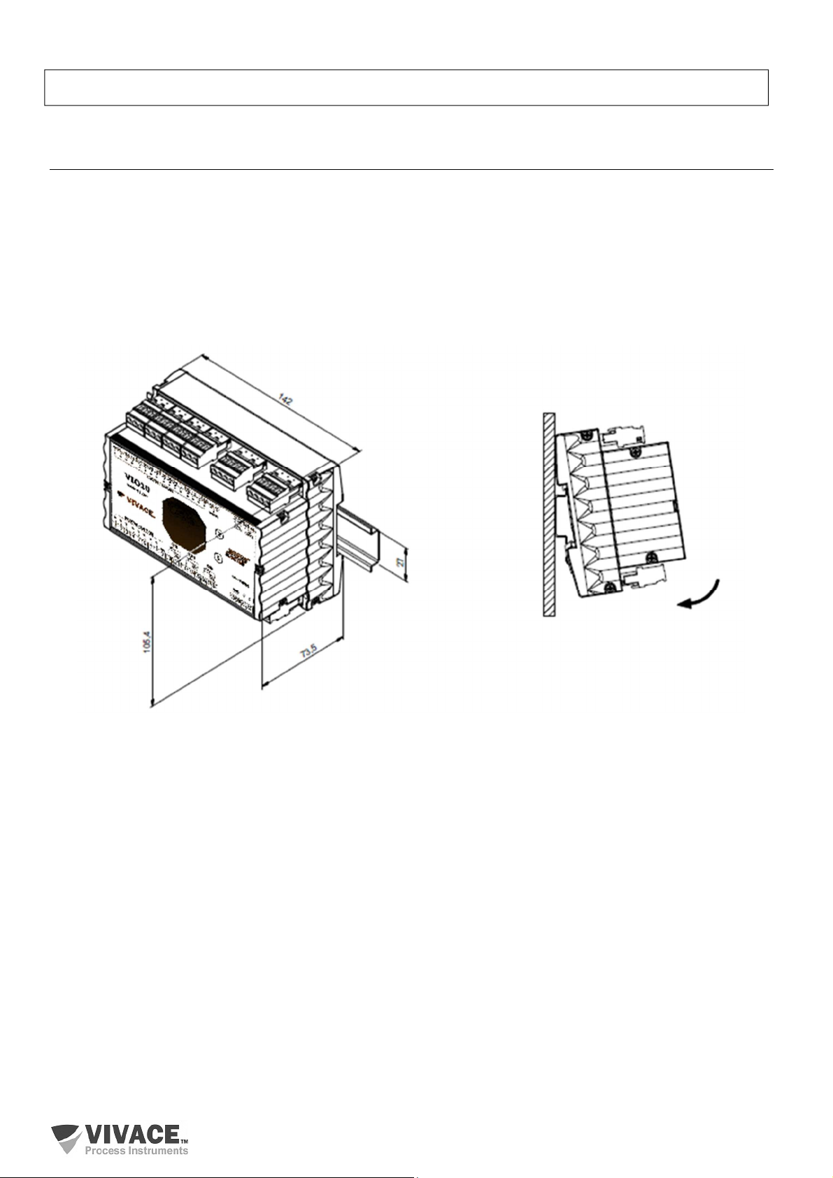
Profibus-PA VIO10-P remote I/O is designed for panel mounting with DIN rail, but maintains good
performance in temperature, humidity and vibration variations.
The electronic circuit is coated with a moisture-proof varnish, but constant exposures to moisture or
corrosive media can compromise its protection and damage the electronic components.
Figure 2.1 shows the dimensional design and mounting forms for VIO10-P.
Figure 2.1 – Dimensional drawing and assembly for VIO10-P.
When mounting VIO10-P on the DIN rail, the upper part of the rail must be attached to the rail bracket
and lightly pressed down on the bottom until it clicks into place.
To remove VIO10-P from the DIN rail, press it up and tilt its top side out of the rail bracket.
9
Page 10
VIO10-P PROFIBUS-PA REMOTE I/O INSTALLATION, OPERATION, CONFIGURATION AND MAINTENANCE MANUAL
NOT
E
Termina
l
Description
Power Supply
Termina
ls –
PWR BUS
– 9 - 32 Vdc not polarized
Grounding
Termina
ls – G
Shield
Terminals
– S
Discrtete Input
Termina
ls –
DI1 to
DI16
Discrete Output
Termina
ls – DO1 to DO8
Output Current
4–20 mA
Termina
ls – OUT1
and OUT2
Sensor
Termina
ls – temperature sensor
or 4-20 mA/0-5 Vdc signal connections
, CH1 to CH3
NOTE
NOT
E: SWITCHING INDUCTIVE LOAD
______________________________________________________________________________________________________________________________
2.2. ELECTRICAL CONNECTION
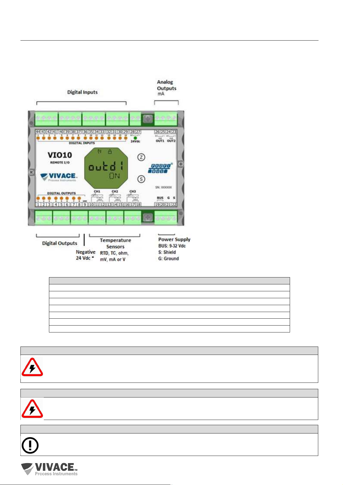
The electrical connection for VIO10-P occurs through its side connectors, reserved for discrete inputs
and outputs, sensors, analog outputs and electrical powering of the equipment.
The following figure identifies VIO10-P connectors.
* When using 24 Vdc external power for digital
outputs (DO1 to DO8), connect the source
negative to terminal 9.
If the same source is connected to terminals 27
and 28, it will not be necessary to connect
terminal 9, since this connection is already made
internally in the VIO10 circuit.
Figure 2.2 – Connection and terminal description for VIO10-P.
All cables used to connect VIO10-P to Profibus-PA sensors and network must be shielded to avoid
interference and noise.
All temperature sensors shall be isolated from the process to avoid interference or noise between the
channels.
It is extremely important to ground the equipment for complete eletromagnetic protection and also to
ensure the correct performance of transmitter on Profibus-PA network.
For inductive DC load, it is recommended to insert a 1N4148 diode in reverse mode for close-load protection
to avoid noise coupling to other cables in the same conduit.
Table 2.1 – Terminal description for VIO10-P.
10
Page 11
VIO10-P PROFIBUS-PA REMOTE I/O INSTALLATION, OPERATION, CONFIGURATION AND MAINTENANCE MANUAL
NOT
E
______________________________________________________________________________________________________________________________
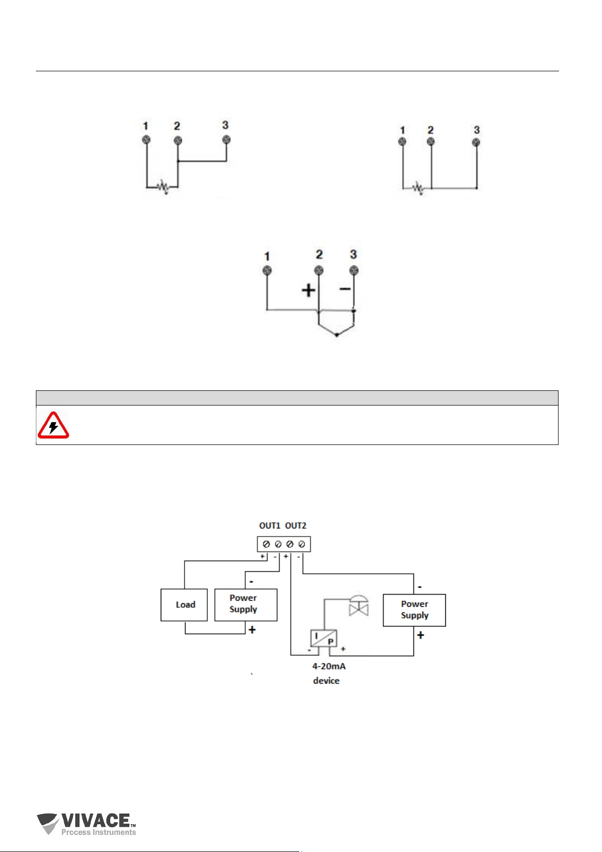
2.3. CONNECTIONS
Following are the VIO10-P connections to several sensor types:
Figure 2.3 - RTD or 2-wire resistive connection. Figure 2.4 - RTD or 3-wire resistive connection.
Figure 2.5 - TC or millivoltage connection.
The unused temperature sensor channels should be short-circuited to avoid the induction of noise.
For control of equipment using the 4-20 mA generation or discrete drive, the connection must be
made according to the following diagram.
Figure 2.6 – Connection between 4-20 mA output and I/P device or discrete action.
11
Page 12
VIO10-P PROFIBUS-PA REMOTE I/O INSTALLATION, OPERATION, CONFIGURATION AND MAINTENANCE MANUAL
______________________________________________________________________________________________________________________________
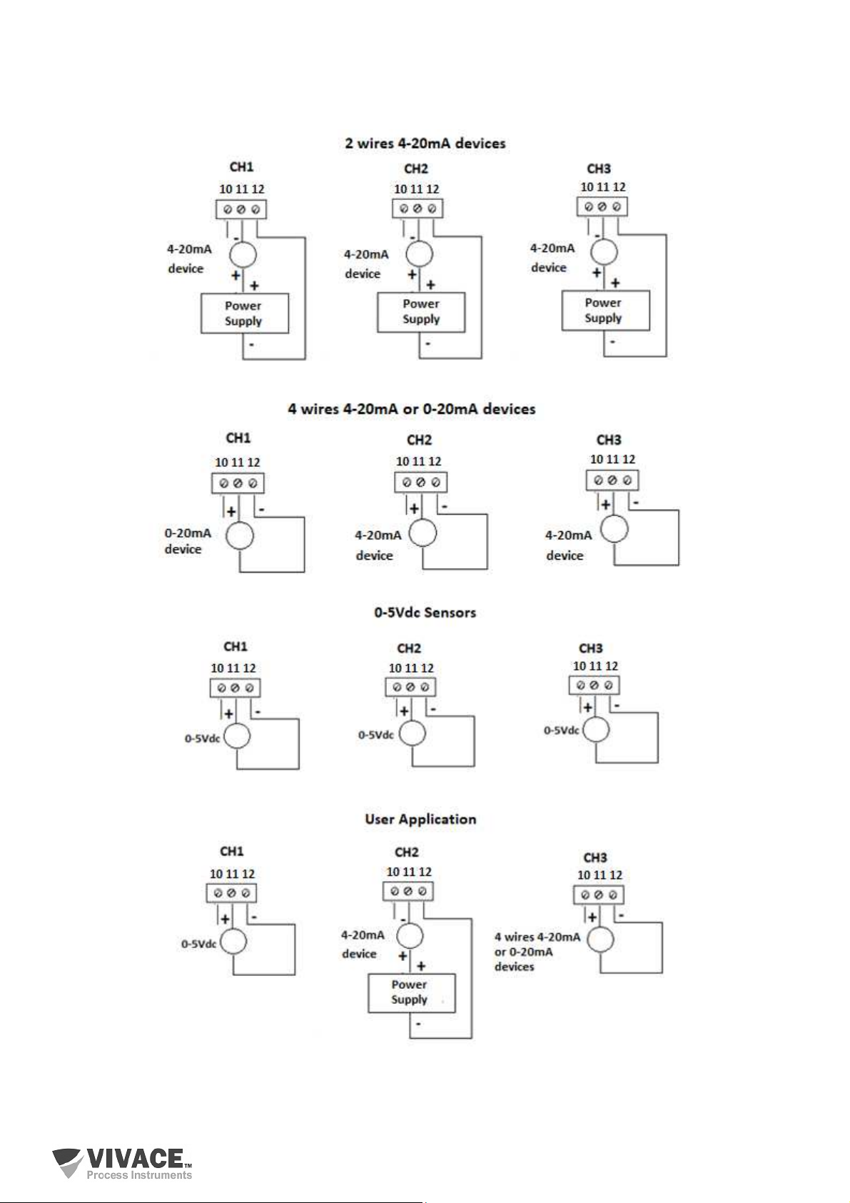
For 4-20 mA or 0-5 Vdc measurement, the connection must be made according to the following
figures.
Figure 2.7 - 4-20 mA or 0-5 Vdc input connections.
12
Page 13
VIO10-P PROFIBUS-PA REMOTE I/O INSTALLATION, OPERATION, CONFIGURATION AND MAINTENANCE MANUAL
______________________________________________________________________________________________________________________________
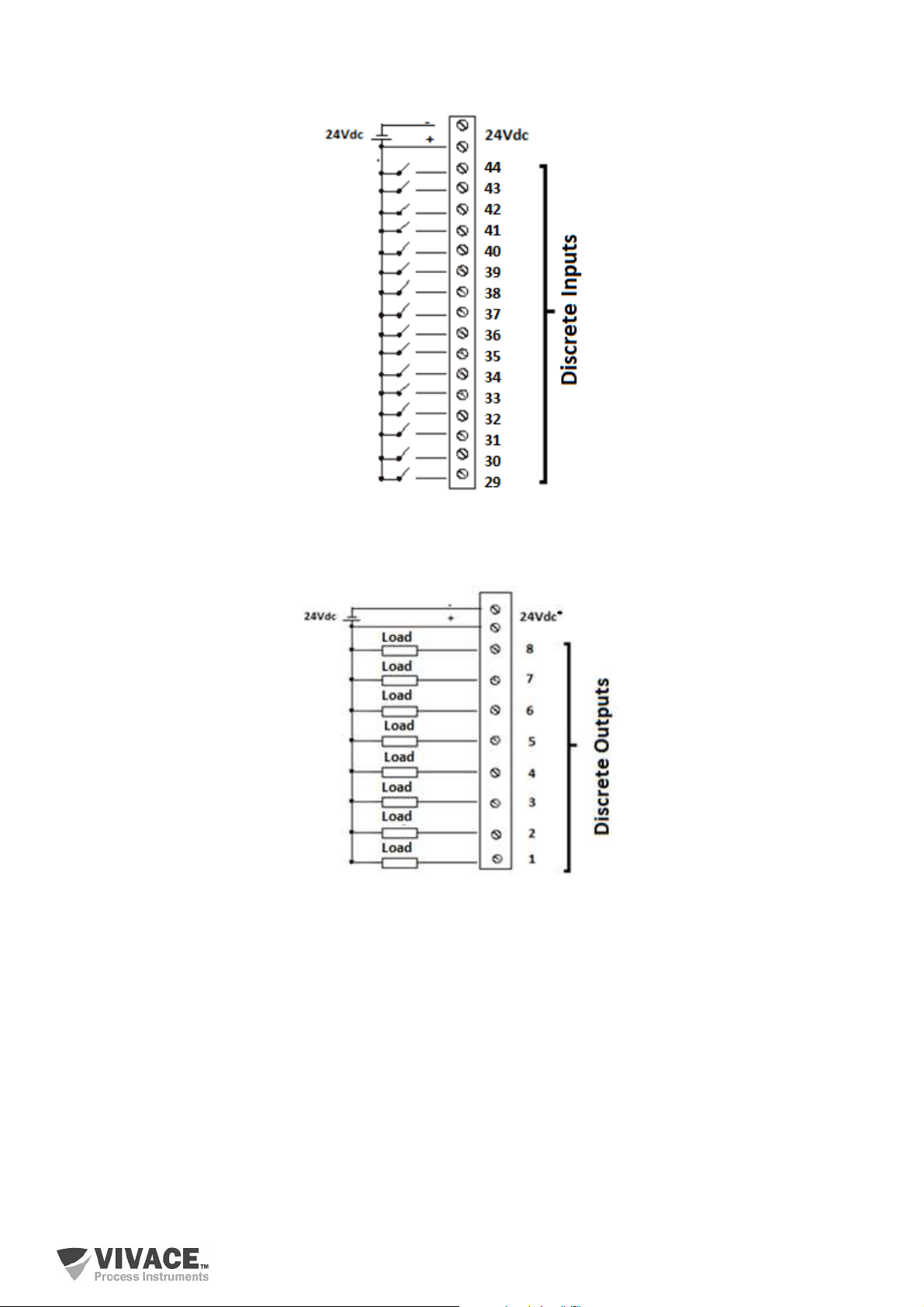
Discrete Input Connections
Figure 2.8 – Discrete input connections.
Discrete Output Connections (Open-Collector)
Figure 2.9 – Discrete output connections.
* When using 24 Vdc external power for digital outputs (DO1 to DO8), connect the source negative to terminal 9.
If the same source is connected to terminals 27 and 28, it will not be necessary to connect terminal 9, since this
connection is already made internally in the VIO10 circuit.
13
Page 14
VIO10-P PROFIBUS-PA REMOTE I/O INSTALLATION, OPERATION, CONFIGURATION AND MAINTENANCE MANUAL
______________________________________________________________________________________________________________________________
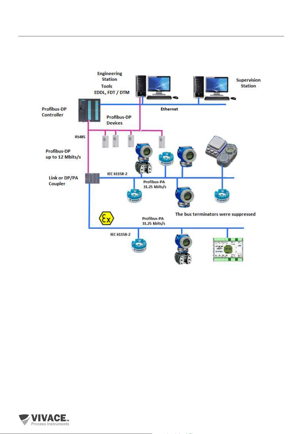
2.4. PROFIBUS NETWORK CONNECTION
Figure 2.10 illustrates the installation of a number of Profibus network elements and the connection
of Profibus PA devices to the Profibus network.
Figure 2.10 – Connection of Profibus-PA devices on the Profibus network.
14
Page 15
VIO10-P PROFIBUS-PA REMOTE I/O INSTALLATION, OPERATION, CONFIGURATION AND MAINTENANCE MANUAL
______________________________________________________________________________________________________________________________
3 CONFIGURATION
Configuration of VIO10-P Profibus-PA remote I/O can be performed with tools based on EDDL
(SIMATIC PDM) and FDT/DTM (eg PACTware). Vivace offers VMT-PROFIBUS configurator to be used on
an Android tablet or mobile phone. Another way to configure VIO10-P is through local adjustment using a
magnetic tool.
3.1. LOCAL CONFIGURATION
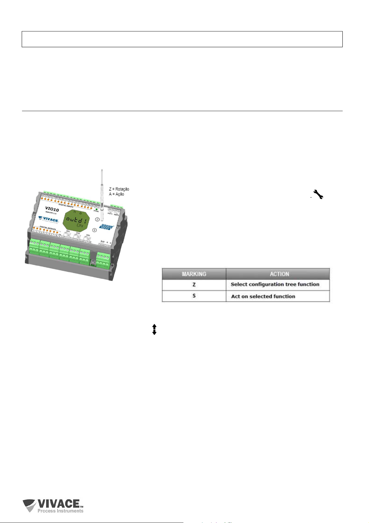
The local configuration of the equipment is realized by actuating the magnetic tool in the marks Z and S,
located in the top of the box. Acting on letter Z starts the local configuration and switches the fields to be
configured. The marking with the letter S is responsible for changing and saving the values for selected
fields. Saving when changing the value on the LCD is automatic.
Figure 3.1 shows Z and S markings for local configuration,
stamped on device enclosure tag and their functions on magnetic
screwdriver actuation.
Touch the magnetic screwdriver on Zero marking (Z). icon
appears to indicate that device has recognized the screwdriver
action. Keep the magnetic screwdriver until “LOCAL ADJST”
message is shown on display, then remove it for 3 seconds. Touch
the magnetic screwdriver on Z marking again, so user can
navigate through local adjust parameters.
Table 3.1 indicates actions executed by magnetic screwdriver
when acting on Z and S orifices.
Figure 3.1 – Z and S markings and
magnetic screwdriver.
Table 3.1 – Z and S marking actions.
Some parameters show the icon to allow user configuration on it by touching the magnetic
screwdriver into Span marking (S). In case the parameter has pre-defined values, those will be rotated on
display, while the magnetic screwdriver remains on Span marking (S).
If the parameter is numerical, this field will enter on edition mode and decimal point will start blinking
and shifting to left. When user removes magnetic screwdriver from S, the least significant digit (in the right)
starts blinking, indicating it is ready for edition. By touching magnetic screwdriver on S, user is enabled to
increase the digit value, from 0 to 9.
After the least significant digit edition, user should remove magnetic screwdriver from S to start the
edition of the next digit (in the left). User will be able to edit each digit independently, until the most significant
digit (5th digit on the left) is complete. After the 5th digit edition, user can also change the signal for the
numerical value still on S orifice.
During each step of edition, user can return to the previous digit (to the right) by touching the
magnetic screwdriver on Z marking, so corrections can be made. By removing the magnetic screwdriver at
any time, user will see the digits blinking until the final step, where the edition mode will be finished, saving
the numerical value configured by user.
15
Page 16
VIO10-P PROFIBUS-PA REMOTE I/O INSTALLATION, OPERATION, CONFIGURATION AND MAINTENANCE MANUAL
______________________________________________________________________________________________________________________________
If the configured value is not acceptable by that device parameter (invalid value), it will be returned
to the last valid value before edition. Depending on the parameter, some values can be shown on numerical
or alphanumerical fields, adjusting the best option view to user.
With the magnetic screwdriver out of Z and S markings, device will leave local adjust mode after
some seconds and monitoring mode will be shown.
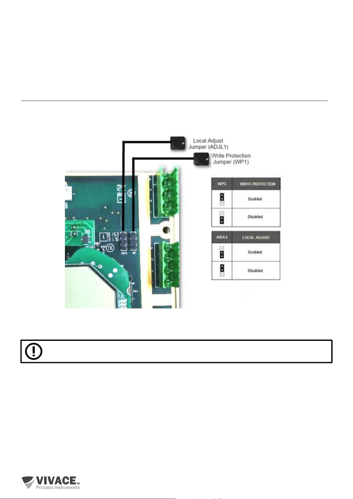
3.2. JUMPER CONFIGURATION FOR LOCAL ADJUST AND WRITE PROTECTION
Figure 3.2 shows jumper positions on main board for enabling/disabling write protection and local
adjustment.
Figure 3.2 – Main board detailing jumpers.
The default positions for jumpers are write protection DISABLED and local adjust ENABLED.
16
Page 17
VIO10-P PROFIBUS-PA REMOTE I/O INSTALLATION, OPERATION, CONFIGURATION AND MAINTENANCE MANUAL
______________________________________________________________________________________________________________________________
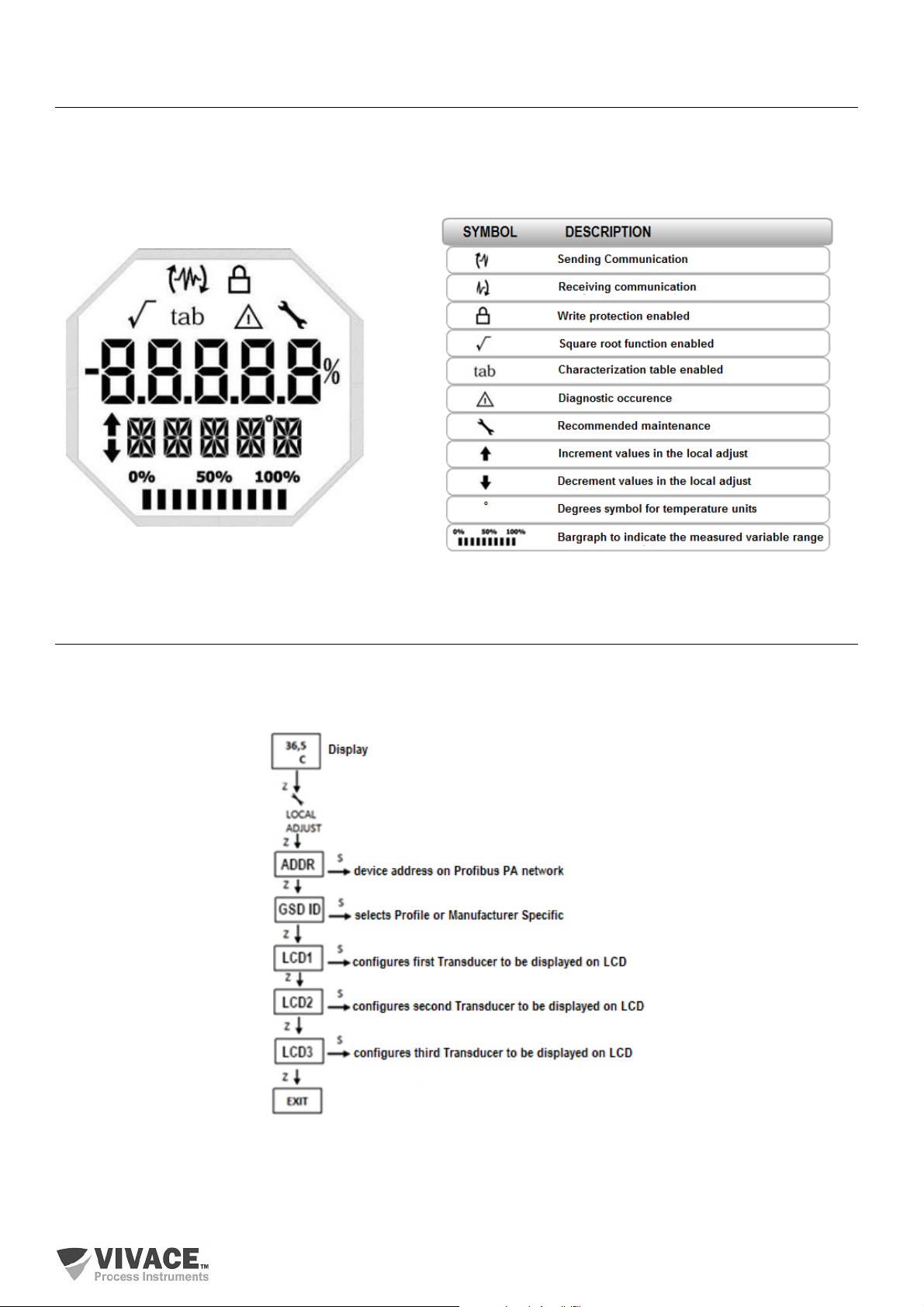
3.3. LIQUID CRYSTAL DISPLAY
The main information regarding the equipment is available on the LCD display. Figure 3.3 shows the
LCD with all its display fields. The numerical field is mainly used to indicate the values of the monitored
variables. The alphanumeric indicates the currently monitored variable, units, or auxiliary messages. The
meanings of each of the icons are described in table 3.2.
Figure 3.3 – LCD fields and icons.
Tabela 3.2 - Descrição dos ícones do display.
3.4. LOCAL ADJUST CONFIGURATION TREE
Figure 3.4 shows available fields for local configuration and the sequence they are presented by
magnetic screwdriver actuation on Z and S markings.
Figure 3.4 – Local adjust configuration tree.
17
Page 18
VIO10-P PROFIBUS-PA REMOTE I/O INSTALLATION, OPERATION, CONFIGURATION AND MAINTENANCE MANUAL
______________________________________________________________________________________________________________________________
3.5. PROFIBUS PROGRAMMER
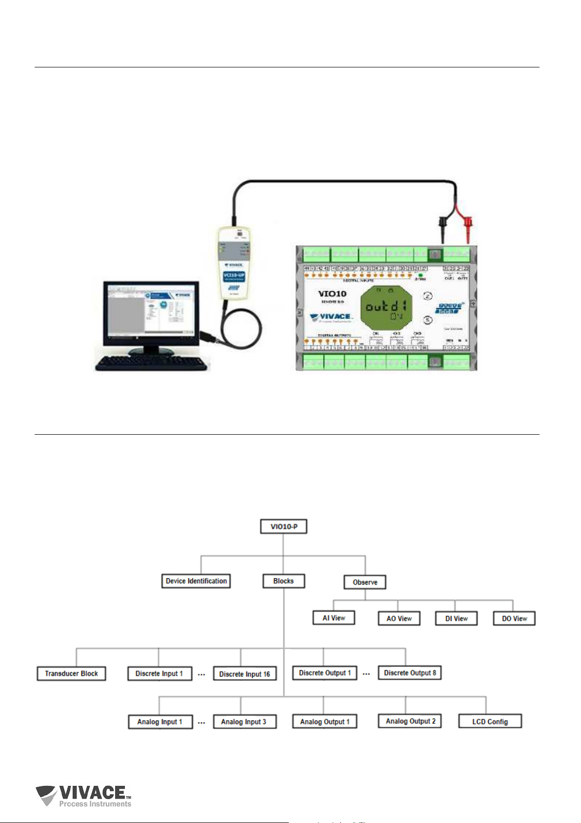
The configuration of the equipment can be made through a programmer compatible with Profibus
PA technology. Vivace offers the interfaces VCI10-P (USB and Bluetooth) as a solution for the identification,
configuration and monitoring of the equipment of the Profibus PA line.
Figure 3.5 shows the connection diagram for configuring the VIO10-P via Vivace VCI10-UP USB
interface, which feeds the device in local mode, with a personal computer that has the PACTware
configuration software installed.
Figure 3.5 – Connection of VCI10-UP to VIO10-P.
3.6. PROFIBUS CONFIGURATOR PROGRAMMING TREE
The configuration tree is a tree-shaped structure with the menus for all software resources available,
as shown on figure 3.6.
For online configuration of the equipment, check it is correctly installed and powered by the adequate
voltage necessary for communication.
Figure 3.6 – VIO10-P programming tree.
18
Page 19

VIO10-P PROFIBUS-PA REMOTE I/O INSTALLATION, OPERATION, CONFIGURATION AND MAINTENANCE MANUAL
______________________________________________________________________________________________________________________________
Device Identification – Main information regarding to the equipment can be found here, such as: Tag,
Device ID, Ordering Code and Firmware Version.
Transducer Block – Menu to configure Transducer Block.
• Basic Settings – Parameters to configure basic adjustments: Sensor Type and Connection Type,
for instance.
Analog Input 1 to 3 – Menu to configure the parameters from 4-20 mA/0-5 Vdc Analog Input Block and
temperature measurement.
• Basic Settings – Parameters to configure Operation Mode, Output Scale (EU0% and EU100%),
Unit, Channel and Damping.
Damping is an electronic pressure reading filter that changes the response time of the transmitter to
smooth the variations in the output readings caused by rapid variations in the input. The damping value can
be set between 0 and 60 seconds and its appropriate value must be based on the process response time,
the stability of the output signal and other system requirements. The default damping value is 0 s.
The value chosen for damping affects the response time of the transmitter. When this value is set to
zero, the damping function will be disabled and the output of the transmitter will immediately react to
changes in its input, so the response time will be as short as possible.
Increasing the damping value leads to an increase in the transmitter response time. At the time the
damping time constant is defined, the output of the transmitter will go to 63% of the value of the change in
the input and the transmitter will continue to approach the input value according to the damping equation.
• Alarm/Warning - This menu sets the Upper and Lower Warning and Alarms Limits. The Hysteresis
Limit is also configured. The measuring unit selected in "Basic Settings" is indicated in this menu, in
addition to checking the current alarm status. The standard graphic of the process variable limits is
also displayed.
• Fail Safe - This menu sets the fault safety type, the fault safety value and displays the unit of
measure selected in "Basic Settings".
• Simulate - This menu enables or disables the Simulation function, sets the value of the position,
shows the unit selected in "Basic Settings" and status.
• Mode Block - This menu shows Target operation mode (manual, automatic or out of service) and
Real, the value of the output variable is set to the unit selected in "Basic Settings" and status. The
alarm status of the position is also observed.
Analog Output 1/2 – Menu to configure the parameters from Analog Output Blocks 1 or 2.
• Basic Settings – Parameters to configure Operation Mode, Input Scale (EU0% and EU100%) and
Unit.
Discrete Input 1/16 – Menu to configure the parameters from Discrete Input Block.
The DI block receives a digital value of the process through the transducer block (TRD) in its channel
and processes it according to its configuration, making the Profibus Class 1 Master available via the OUT_D
parameter.
It has operating mode, inversion, simulation and error handling. The DI block also allows user to
simulate a digital process value via the SIMULATE_D parameter. This parameter is used to facilitate testing,
for example, when doing the control plant startup. When active, the transducer block value and status will
be superimposed by the simulated value and status. When disabled, the process value will be provided by
the transducer block to the DI block.
The DI block also allows the input logic level to be inverted through the INVERT parameter, which
also happens during the simulation. With INVERT active, the parameter PV_D will be inverted before the
output OUT_D is updated. The algorithm of the DI block includes the handling of errors and faults as well
as seen for the previous blocks.
19
Page 20

VIO10-P PROFIBUS-PA REMOTE I/O INSTALLATION, OPERATION, CONFIGURATION AND MAINTENANCE MANUAL
______________________________________________________________________________________________________________________________
Discrete Output 1/8 – Menu to configure the parameters from Discrete Output Blocks.
The DO block can receive a discrete setpoint value (SP_D) via cyclic communication or via user,
when its operation mode is automatic (Auto). In this case, it receives value and status through SP_D
parameter. In this condition it is important to note that the status must be greater than or equal to Good
(0x80).
When its operating mode is in cascade (RCas), setpoint value and status are supplied via parameter
RCAS_IN_D by the Profibus Class 1 master, through cyclic communication. In this condition, the status
must equal Initialization Acknowledge (0xC4). This setpoint value is processed according to the algorithm
of the block and made available to the transducer block (TRD) that will act on the final control element, such
as by actuating an on/off valve.
Similar to the AO block, the DO block supports the following operating modes: O/S, MAN, RCAS,
LO and AUTO. As the other blocks, DO allows simulation. This parameter is used to facilitate testing, for
example, when doing the control plant startup. The DO block provides the discrete value as well as the
status to the TRD block through the READBACK_D parameter.
Similarly to the DI block, it has the parameter INVERT, where you can invert the discrete value of
the setpoint, either in Auto or RCas mode. The DO block also has error and fault handling. If there is a loss
of cyclic communication with the Profibus Class 1 master and the discrete setpoint is no longer up-to-date,
you can configure the type of treatment that should happen with the output of the DO block.
LCD Config – Menu to configure LCD for up to 3 variables: Monit 1, Monit 2 and Monit 3.
• Monit x – On these menus user can configure Function Blocks (Physical, Transducer, Analog Input
1 to 3 or Analog Output 1 to 2), Relative Index, Structure Element, Mnemonic, decimal point number
(1, 2, 3 or 4) and enable/disable the alphanumeric field.
Observe - In this menu, the values and the status of the parameters of the TRD, AI, AO, DI and DO blocks
are monitored.
20
Page 21
VIO10-P PROFIBUS-PA REMOTE I/O INSTALLATION, OPERATION, CONFIGURATION AND MAINTENANCE MANUAL
______________________________________________________________________________________________________________________________
3.7. FDT/DTM CONFIGURATION
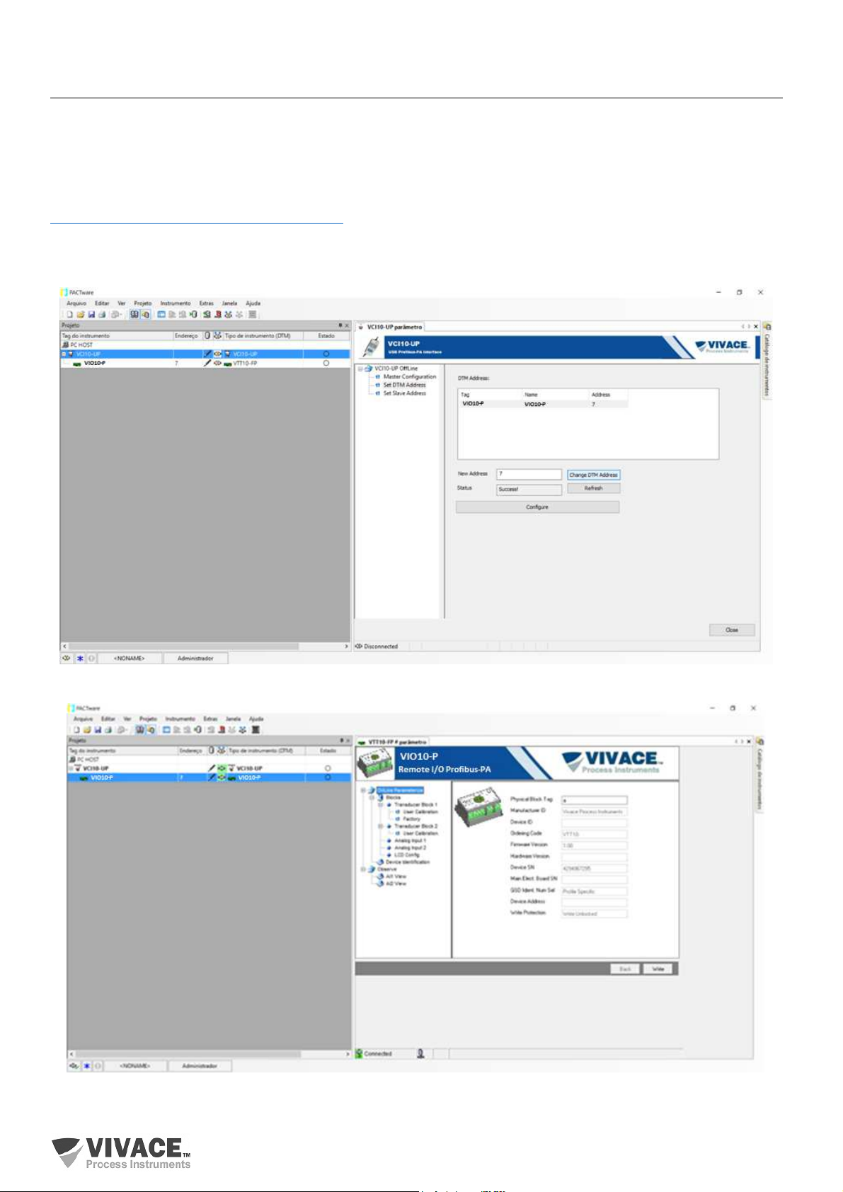
FDT/DTM-based tools (Ex. PACTware®, FieldCare®) can be used for device information,
configuration, monitoring, calibration and diagnosis with Profibus PA technology. Vivace offers the DTM files
for all of its devices (HART® and Profibus PA).
PACTware® is property of PACTware Consortium and can be found on
http://www.vega.com/en/home_br/Downloads.
The following figures exemplify DTM configuration screens for VIO10-P using Vivace’s VCI10-UP
interface and PACTware®.
Figure 3.7 – Configuration for communication interface using PACTware.
Figure 3.8 – Screen for VIO10-P information view on PACTware.
21
Page 22

VIO10-P PROFIBUS-PA REMOTE I/O INSTALLATION, OPERATION, CONFIGURATION AND MAINTENANCE MANUAL
______________________________________________________________________________________________________________________________
3.8. CYCLIC CONFIGURATION
VIO10-P has 16 function blocks for discrete input (16 DI – Discrete Input), 8 blocks for discrete output
(8 DO – Discrete Output), 3 function blocks for analog input (3 AI - Analog Input Block) and 2 blocks for
analog output (2 AO - Analog Output Block). It also has na Empty Module for applications where only some
of the blocks will be configured.
The 3 input blocks (AI) are destinated to temperature or current/voltage input measurement (0–20 mA;
4–20 mA; 0–5 Vdc). The 2 output blocks (AO) are used to generate the analog current outputs: 4–20 mA.
The following ciclic block order must be respected: AO1, AO2, AI1 to AI3, DO1 to DO8, DI1 to DI16.
When any block is not used, user must fill it with the Empty Module.
Most Profibus configurators use two directories where the GSD and BITMAP files from the various
manufacturers are located. The GSD and BITMAPS for Vivace equipments are available on the website
(www.vivaceinstruments.com.br).
Follow the procedure below to integrate the VIO10-P into a Profibus system (these steps apply to all
Profibus PA Vivace line devices).
• Copy the GSD file of the VIO10-P to the directory where all the GSD files of the Profibus configurator,
usually called "GSD" are located;
• Copy the BITMAP file of the VIO10-P to the directory where all the BMP files of equipment of the
Profibus configurator, usually called "BMP";
• After choosing the PROFIBUS-DP master, set the communication rate. Do not forget that DP/PA
couplers can have the following communication rates: 45.45 kbits/s (Siemens), 93.75 kbits/s (P+F)
and 12 Mbit/s), SK3). The IM157 device link can have up to 12 Mbits/s;
• Add the VIO10-P and specify its address on the bus;
• Select the cyclic configuration through the parameterization, according to the GSD file, which
depends on the application, as seen previously. For the AI block, the VIO10-P provides master the
value of the process variable in 5 bytes, the first four in the floating point format (IEEE-754) and the
fifth byte forming the status that the information of the quality of this measurement.
• Some devices support the cyclic modules in the "long" and "short" formats. If there is a failure in the
cyclic communication, check if by changing the chosen format, the communication is established
successfully.
For Block AO, it is possible to have several options, according to GSD file. Through analog output
block (AO) Class 1 master executes ciclic services. User must choose the most adequate configuration for
his application.
If VIO10-P Block AO is in AUTO, it will receive value and status from Class 1 master setpoint. In
addition, user may change this value via Class 2 master, if setpoint status is 0x80 (“Good”), where the
following configurations can be chosen:
SP;
SP/CHECKBACK;
SP/READBACK/POSD;
SP/READBACK/POSD/CHECKBACK
If Block AO is in RCAS, VIO10-P will receive value and statusreceberá valor e status from setpoint
(RCAS_IN) only via Class 1 master, where status will equals 0xC4 (“IA”). The following configurations can
be chosen:
SP;
SP/CHECKBACK;
SP/READBACK/POSD;
SP/READBACK/POSD/CHECKBACK;
RCASIN/RCASOUT;
RCASIN/RCASOUT/CHECKBACK;
SP/READBACK/RCASIN/RCASOUT/POSD/CHECKBACK
22
Page 23
VIO10-P PROFIBUS-PA REMOTE I/O INSTALLATION, OPERATION, CONFIGURATION AND MAINTENANCE MANUAL
NOTE
______________________________________________________________________________________________________________________________
• On DO and DI Blocks, user can choose the following options, where for DO Block, only one of
them is allowed per block.
If DO Blocks are in AUTO mode, VIO10-P will receive value and status from Profibus Class 1 master
discrete setpoint. User can write this value through Class 2 master. In this case, setpoint status must equals
0x80 (“Good”) andu ser can choose any of the following options:
• SP_D
• SP_D+RB_D
• SP_D+RB_D+CB_D
If DO Blocks are in RCAS, the equipment will receive value and status from discrete setpoint only
via Class 1 master, where status equals 0xc4 (“IA”). User can choose any of the following configurations:
• SP_D
• SP_D+RB_D
• SP_D+RB_D+CB_D
• RIN_D+ROUT_D
• RIN_D+ROUT_D+CB_D
• SP_D+RB_D+RIN_D+ROUT_D+CB_D
• If necessary, activate the watchdog condition, which causes the equipment to assume a safe fault
condition upon detection of a loss of communication between the slave device and the Profibus-DP
master.
Check byte swap condition (MSB with LSB inversion and, in some cases, nibble inversion), as for
some systems it will be necessary on handling cyclic data.
VIO10-P has the GSD identifier number equal to 0x0FF9 (Manufacturer Specific) and can still work
with the value 0x9760 (Profile Specific).
DD, DTM and GSD for VIO10-P can be found on the website: www.vivaceinstruments.com.br
For further information on the Profibus PA technology, refer to the Vivace website in the Installation,
Operation and Configuration Manual - Profibus PA - blocks, parameters and structure.
This equipment has several functional blocks, so it is recommended to set the number of retries
to 3 or more, in addition to increasing the slot time (indicates how long the PROFIBUS-DP master
will wait for a response from the slave before resending a frame) in order to avoid retransmissions.
23
Page 24

VIO10-P PROFIBUS-PA REMOTE I/O INSTALLATION, OPERATION, CONFIGURATION AND MAINTENANCE MANUAL
______________________________________________________________________________________________________________________________
DP/PA Link
In a Profibus DP network it is common to have Link Devices DP/PA to provide an increase of the
communication rate up to 12 Mbits/s and even increase the addressing capacity, since these devices are
slaves in the Profibus-DP network and teachers in the Red Profibus PA network. Each Link Device may
have connected several DP/PA couplers.
Siemens has a Link device DP/PA which is the model IM157. This device works with a DP/PA
adapter at a communication speed of 31.25 kbits/s and in the Profibus-DP network from 9.6 kbits/s to 12
Mbits/s. The IM157 and each coupler are powered with 24 Vdc. The maximum number of field devices per
link is limited to 30 or 64 computers, but this depends on the model and the number of bytes exchanged
cyclically.
When using the Link Device it is necessary to verify that the cyclic modules for Vivace Process
Instruments equipment are included in your GSD file.
If not, these should be included. To do so, access the Siemens website and download the GSD tool. This
is a tool that allows you to extend the GSD file of Siemens link devices (IM157, IM53) by adding the modules
of new Profibus PA devices that are not in the GSD file. You must have the GSD of the link device and
Vivace team in the directory where the GSD Tool was installed and when running, choose the option to
extend the GSD file of the link device, choose the link template and the GSD of the team and run. After
execution, note that a section has been created for the Vivace device with its cyclic modules.
24
Page 25
VIO10-P PROFIBUS-PA REMOTE I/O INSTALLATION, OPERATION, CONFIGURATION AND MAINTENANCE MANUAL
______________________________________________________________________________________________________________________________
4 MAINTENANCE
VIO10-P remote I/O, like all Vivace products, is rigorously evaluated and inspected before being
sent to the customer. However, in case of a malfunction, a diagnosis can be made to check whether the
problem is located in the installation, in the configuration of the equipment or if there is a problem with the
device.
4.1. ASSEMBLY AND DISASSEMBLY PROCEDURES
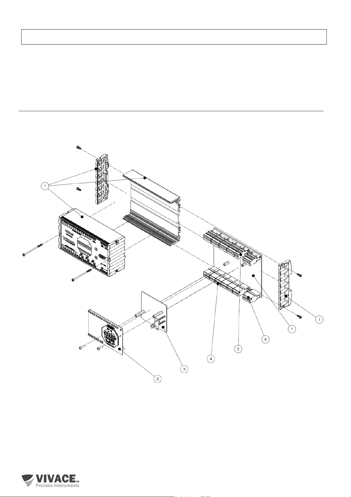
Figure 4.1 shows in detail all components of the VIO10-P. Before disassembling the equipment, it
must be switched off. Maintenance of electronic boards should not be performed under penalty of loss of
equipment warranty.
Figure 4.1 – Explosion view for VIO10-P.
25
Page 26
VIO10-P PROFIBUS-PA REMOTE I/O INSTALLATION, OPERATION, CONFIGURATION AND MAINTENANCE MANUAL
______________________________________________________________________________________________________________________________
4.2. SPARE PARTS
VIO10-P spare parts that can be purchased directly from Vivace Process Instruments are listed in
table 4.1.
VIO10-P - SPARE PARTS CODES
DESCRIPTION
ENCLOSURE (includes screws) 1 2-10092
DISPLAY WITH LED BOARD (includes screws) 2 2-10093
MAIN BOARD (includes spacers) 3 2-10094
TERMINAL BLOCK PLUG 3 BORNES 4 1-10013
TERMINAL BLOCK PLUG 2 BORNES 5 1-10022
TERMINAL BLOCK PLUG 4 BORNES 6 1-10012
ANALOG BOARD (includes headers, spacers and grounding terminals) 7 2-10091
Table 4.1 – List of spare parts for VIO10-P.
REFERENCE
FIG. 4.1
CODE
26
Page 27

VIO10-P PROFIBUS-PA REMOTE I/O INSTALLATION, OPERATION, CONFIGURATION AND MAINTENANCE MANUAL
______________________________________________________________________________________________________________________________
5 CERTIFICATION
VIO10-P was projected to attend national and international regulation for intrinsic safety.
Certificates are pending.
27
Page 28
VIO10-P PROFIBUS-PA REMOTE I/O INSTALLATION, OPERATION, CONFIGURATION AND MAINTENANCE MANUAL
______________________________________________________________________________________________________________________________
6 TECHNICAL CHARACTERISTICS
6.1. IDENTIFICATION
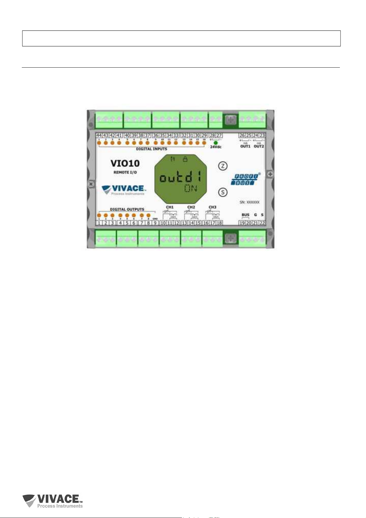
VIO10-P has a label that identifies the equipment connections, its model and serial number, as well
as showing the Z and S positions where the magnetic switch must be positioned to carry out the local
adjustment, as shown in figure 6.1.
Figure 6.1 – Identification label for VIO10-P.
28
Page 29
VIO10-P PROFIBUS-PA REMOTE I/O INSTALLATION, OPERATION, CONFIGURATION AND MAINTENANCE MANUAL
______________________________________________________________________________________________________________________________
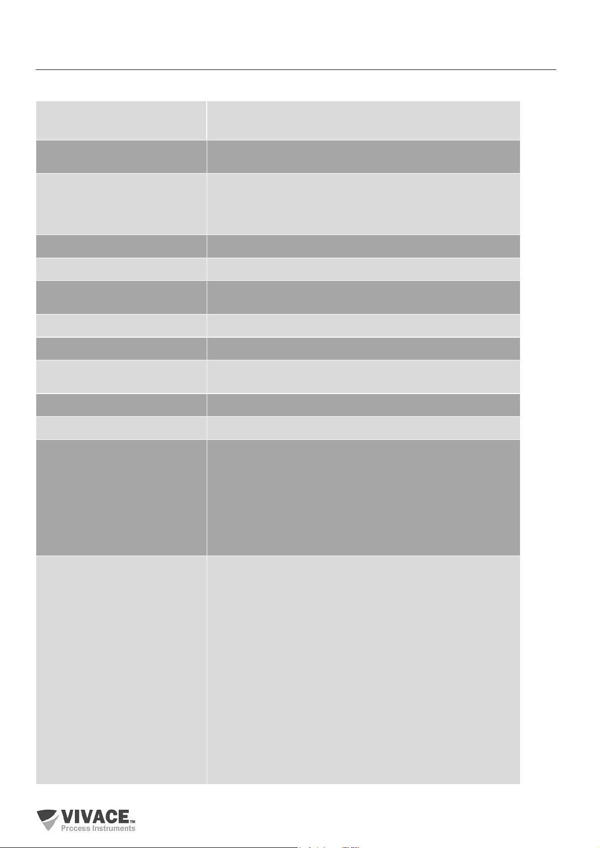
6.2. TECHNICAL SPECIFICATION
The table below shows Technical specifications for VIO10-P.
Accuracy Temperature: According to Tables 6.2, 6.3 and 6.4
Inputs/Outputs: ± 0.1% Calibrated Span
Supply Voltage / Quiescent Current
Output Load Limit
Protocol of Communication / Function
Block
9 to 32 Vcc, no polarity / 12 mA
Profibus-PA /
16 Discrete Input (DI)
08 Discrete Output (DO)
03 Analog Input (AI)
02 Analog Output (AO)
Certification in Hazardous Area Intrinsically Safe (pending)
Ambient Temperature Limit -20 to 70°C
Configuration Remote configuration through tools based on EDDL or FDT / DTM. Local
configuration via magnetic key.
Mounting In field or panel, using DIN rail
Degree of Protection IP20
Type of Electrical Insulation (between
Profibus-PA bus, inputs and outputs)
Housing Material Aluminum / Plastic
Approximate weight 500 g
Discrete Inputs 16 Inputs
Discrete Outputs 8 Outputs: NPN transistors, open collector. They work with relays, solenoids
Galvanic Isolation, 1,5 kVac
Typical external power supply: 24 Vdc (18 to 30 Vdc, maximum consumption
120mA)
Optical Isolation of 5,000 Vac.
Level in ON state (True Logical) 15 - 30 Vdc.
Level in OFF state (Logical False) 0 - 5 Vdc
Typical Impedance 3.9 kΩ.
and other DC loads with maximum current of 0.5 A per output. All outputs
share the same ground and are isolated from each other, as well as from the
Profibus-PA network.
Typical external power supply 24 Vdc (18 to 30 Vdc, max. 40mA) - same
source of inputs, 24Vdc
Optical Isolation of 5,000 Vac
Maximum switching voltage: 30 Vdc
Maximum Saturation Voltage: 0.55 V at 0.5 A
Maximum Output Current: 0.6 A
Indication logic: ON when the transistor is on.
Power-Up Condition: OFF
Thermal Protection: Thermal Shutdown: 150-200 ° C; Thermal Hysteresis 10
at 25 ° C; Over current protection: 1.3 A at 24 Vdc maximum
* With inductive loads use RC filters or diode in reverse mode as filter.
Table 6.1 – Technical specifications for VIO10-P.
29
Page 30
VIO10-P PROFIBUS-PA REMOTE I/O INSTALLATION, OPERATION, CONFIGURATION AND MAINTENANCE MANUAL
______________________________________________________________________________________________________________________________
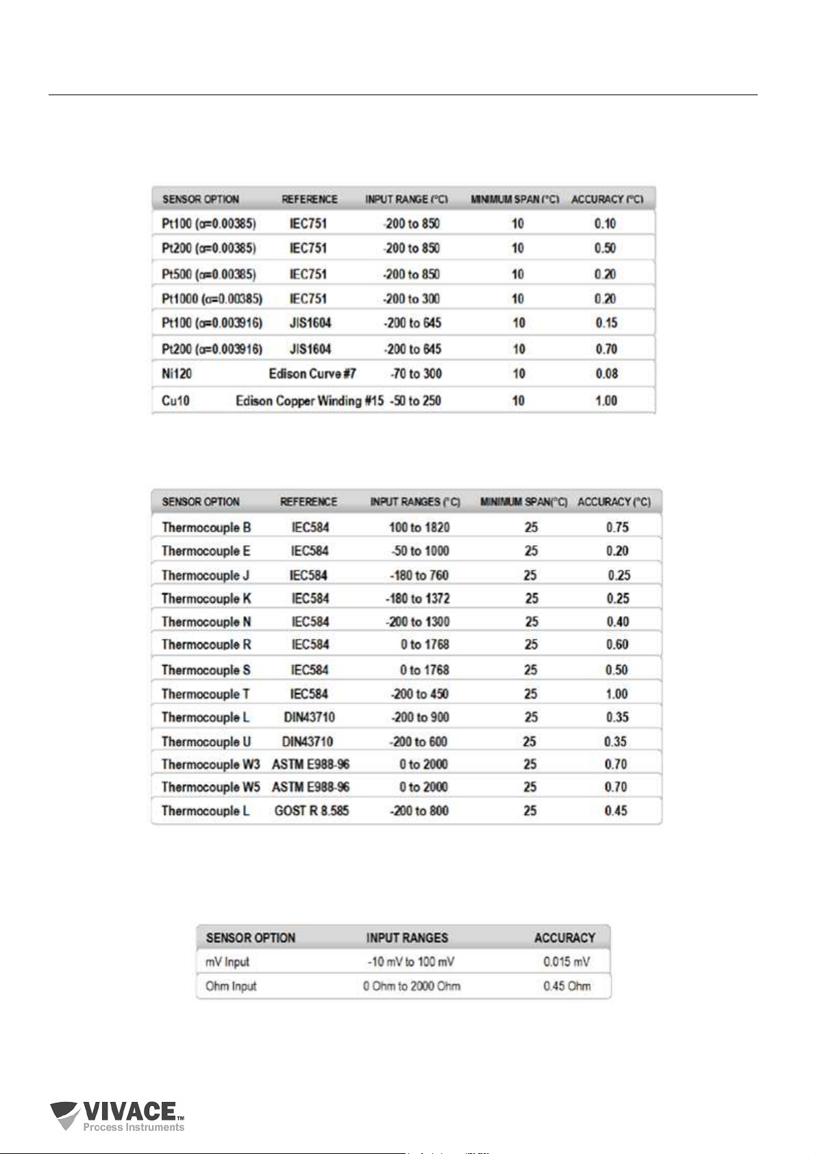
6.3. TEMPERATURE SENSORS
The following tables list the sensor types and their proper working ranges, plus minimum range for
correct operation and accuracy.
RTD – Temperature sensor based on resistance for 2 or 3-wire connection:
Table 6.2 – RTD’s technical characteristics.
TC – Temperature sensor based on milivoltage for 2-wire connection:
Table 6.3 – TC’s technical characteristics.
Ohm or mV – Linear resistive or milivoltage sensor for 2 or 3-wire connection:
Table 6.4 – Technical characteristics for resistive or mV sensors.
30
Page 31
VIO10-P PROFIBUS-PA REMOTE I/O INSTALLATION, OPERATION, CONFIGURATION AND MAINTENANCE MANUAL
______________________________________________________________________________________________________________________________
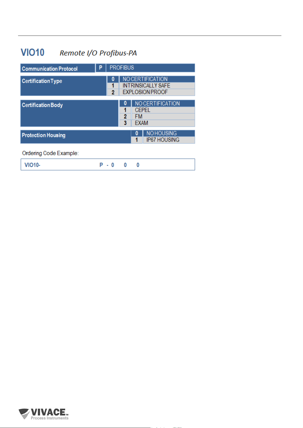
6.4. ORDERING CODE
31
Page 32
VIO10-P PROFIBUS-PA REMOTE I/O INSTALLATION, OPERATION, CONFIGURATION AND MAINTENANCE MANUAL
______________________________________________________________________________________________________________________________
7 WARRANTY
7.1 GENERAL CONDITIONS
Vivace ensures its equipment from any defect on manufacturing or component quality. Problems
caused by misuse, improper installation or exposure to extreme conditions are not covered by this warranty.
The user can repair some equipment by replacing spare parts, but it is strongly recommended to
forward it to Vivace for diagnosis and maintenance in cases of doubt or impossibility of correction by the
user.
For details about the product warranty, see the general term warranty on Vivace website:
www.vivaceinstruments.com.br.
7.2 WARRANTY PERIOD
Vivace ensures the ideal operating conditions of their equipment by a period of two years, with full
customer support regarding to installation, operation and maintenance for the best use of the equipment.
It is important to note that even after warranty period expires, Vivace assistance team is ready to
assist customer with the best support service, offering the best solutions for the installed system.
32
Page 33
VIO10-P PROFIBUS-PA REMOTE I/O INSTALLATION, OPERATION, CONFIGURATION AND MAINTENANCE MANUAL
______________________________________________________________________________________________________________________________
APPENDIX
Technical Analysis Solicitation Form
Company: Unit/Department: Shipping Invoice nº:
Standard Warranty: ( )Yes ( )No Extended Warranty: ( )Yes ( )No Buying Invoice nº:
COMMERCIAL CONTACT
Complete Name: Position:
Phone and Extension: Fax:
e-mail:
TECHNICAL CONTACT
Complete Name: Position:
Phone and Extension: Fax:
e-mail:
EQUIPMENT DATA
Model: Serial Num.:
PROCESS INFORMATION
Environment Temperature (ºC) Work Temperature (ºC)
FSAT
Min: Max: Min: Max:
Operation Time: Fail Date:
FAIL DESCRIPTION: Here user should describe in detail the observed behaviour of product, frequency of fail occurence and
repeatability. Also, should inform operational system version and a quick description of control system architecture where the
equipment was installed.
ADDITIONAL OBSERVATION:
33
Page 34

VIO10-P PROFIBUS-PA REMOTE I/O INSTALLATION, OPERATION, CONFIGURATION AND MAINTENANCE MANUAL
______________________________________________________________________________________________________________________________
34
 Loading...