


MP-I201
Owner’s Manual

2
MP-S201 | Version 1
All rights reserved. No part
of this publication may be
reproduced, stored in or
introduced into a retrieval
system, or transmitted in
any form, or by any means
(electronic, mechanical,
photocopying, recording
or otherwise) without the
prior written permission of
Vitus Audio. Any person who
does any unauthorized act
in relation to this publication
may be liable to criminal
prosecution and civil claims for
damages.
Information contained in this
manual is subject to change
without notice, and whilst it
is checked for accuracy, no
liabilities can be accepted for
errors.

3
MP-S201| Version 1
table of contents
on a personal note
Certificate . . . . . . . . . . . . 4
from the creator
Foreword . . . . . . . . . . . . . 5
introduction
About this manual . . . . . . . . 6
Introduction to the Masterpiece
Series . . . . . . . . . . . . . . . 6
Differences in temperature . . . 7
Handling the unit . . . . . . . . 7
1. getting started
Unpacking the box . . . . . . . . 8
What’s in the box . . . . . . . . . 8
The topology of
the volume control. . . . . . . . 9
2. connecting
Connecting the MP-I201 . . . . . 10
Turning the MP-I201 on and off. 11
Moving and transporting
the MP-I201 . . . . . . . . . . . . 11
MP-I201 rear panel: Plugs . . . . 12
MP-I201 rear panel Picture . . . . 13
3. operation
Operation modes . . . . . . . .15
Functions – left front panel . . .16
Functions – right front panel . .17
MP-I201 discription of
the elements in the menu. . . . . 18
MP-I201 menu structure . . . . . 19
4. operation & service
Safety notice . . . . . . . . . . . 20
Mains supply voltage . . . . . .20
Maintenance . . . . . . . . . . . 20
Mains fuse . . . . . . . . . . . .21
Replacing a blown fuse . . . . .22
5. warranty
Warranty . . . . . . . . . . . . .23
6. specifications
MP-I201 Specifications . . . . . . 26
7. examples operation
Example 1 . . . . . . . . . . . .28
Example 2 . . . . . . . . . . . . . 29
Example 3 . . . . . . . . . . . .30
Example 4 . . . . . . . . . . . .31
Example 5 . . . . . . . . . . . .32
Example 6 . . . . . . . . . . . .33
Example 7 . . . . . . . . . . . .34
Example 8 . . . . . . . . . . . . . 35
Example 9 . . . . . . . . . . . .36
Example 10 . . . . . . . . . . . . 37
Example 11 . . . . . . . . . . . . 38
Example 12 . . . . . . . . . . . . 39
Connecting devices 1 . . . . . . 40
Connecting devices 2 . . . . . . 41
8. pictures
MP-I201 Front. . . . . . . . . . . 42
MP-I201 Inside . . . . . . . . . . 43

4
MP-S201 | Version 1
on a personal note
Certificate
Model: MP-I201
Product ID/Serial
__________________________________
Product Build Date
__________________________________
Signed
__________________________________
All products details, specifications and
measurements are recorded for your MPI201 and kept by Vitus Audio.

5
MP-S201| Version 1
from the creator
Foreword
First of all, thank you for
choosing the Vitus Audio
MP-I201 integrated amplifier,
we are sure you will enjoy it
for many years to come. When
purchasing a Vitus Audio
product, you are guaranteed a
musical performance,
which exceeds the current
musical standards. Vitus
Audio is dedicated to musical
performance rather than
technical details and high
performance measures.
We believe that many
manufactures are blinded by
the current available theory,
instead of looking for new
answers.
At Vitus Audio everything
works until proven not to.
This way we always try to
push the limits and explore
the unexplored. As a result
of this, many of the solutions
we use today are considered
to be “impossible to ever
get working”,however they
have convinced many people
and reviewers world wide
of the opposite. Before any
of our new topologies are
implemented in our products,
they are carefully reviewed by
our dedicated listening panel.
This way we can guarantee
the correct level of musically
performance and robustness.
Generally we’re after super
neutral, super detailed and
super dynamic reproduction
without “loosing” the nerve
in the music which often is
a drawback of many high
end amplifiers. Our real
strongholds are complete
silence, unbelievable depth
and width in the soundstage
resulting in a far more open
sound with higher resolution
-you could say, closer to the
artist. As a result of the above,
our amps do not “focus” on
any specific frequencies - i.e.
no extension of top or bas,
which of course results in high
clarity of the midrange since
it’s “naturally present”!
Hans Ole Vitus

6
MP-S201 | Version 1
introduction
About this manual
This is your MP-I201 owner’s
manual. The following pages
will describe, as clearly as
possible, how to get your MPI201 operating fast and simple.
Although some operations are
self-explanatory, we strongly
suggest you read this manual
to avoid any damage to the
unit. The manual is designed
to be helpful. If there are
points you feel we could cover
better, or that we have missed
out – please tell us.
Important
information is
presented like
this. Ignoring this
information may cause
damage to you or the
unit. Damage caused
to the unit by ignoring
this information might
invalidate the warranty.
Introduction to the
Masterpiece Series
The Vitus Audio Masterpiece
Series is a true high-end series
of products, which is build on
our true dedication to neutral
music reproduction. Every
detail is carefully thought
through, and all choices made
during development, where
based purely on listening, and
not measuring. Only the best
available materials are used to
ensure an overall quality which
will last for many years, when
treated right.

7
MP-S201| Version 1
introduction
F
120
100
80
60
40
- 40
20
- 20
0
C
50
40
30
- 20
20
10
- 10
- 40
- 30
0
Handling the unit
This unit is VERY
heavy – make sure
to be at least two
people to unpack the
unit. You might damage
both your back and
the unit if extra care
is not applied. Vitus
Audio A/S cannot
be held responsible
for any damage that
is a consequence of
uncareful handling of
the unit.
Differences in
temperature
After unpacking
allow 24 hours
for the product
to reach room
temperature before
connecting up and
switching on. This is
to allow condensation
to dissipate, which
might otherwise
cause damage to the
electronics. Remember
also that condensation
can form when you
move the unit from a
cold place to a warm
place.
CAUTION
1. getting started

8
MP-S201 | Version 1
Crate Top
Crate Bottom
Crate
MP-I201
Andromeda
Power Cable
Andromeda
Power Cable
Standard
Power Cable
Unpacking the box
After you have removed the
top, it is possible to remove
the top foam corners. Next
to the ampifier you will find
the power cord, brochure and
manual. Now remove the sides
Two people carefully lift the
amplifier of the box bottom
and put it directly onto the
floor.
Store the empty box and the
protective foam for later use.
What’s in the box
MP-I201
2x Andromeda Power Cable
Standard Power Cable
CD containing Manual and
Brochure
Foam Top
Foam Bottom
Crate Top
Crate
Crate Bottom
1. getting started
CD containing
Manual and
Brochure
Foam Corners
Bottom
Foam Bottom
Foam Top
Foam Corners
Top

9
MP-S201| Version 1
1. getting started
1. getting started
The topology of the volume
control used in the MP-I201
is very different compared
to the “standard”. The MPI201 uses a series of fixed
resistor networks to control
the volume. Relays are used
to switch between the resistor
networks. Across all volume
steps, a fixed resistor is in
series with the signal path. This
gives the best performance
possible. When you change
volume, a different number of
shunt resistors are used.
To prevent pop in the output,
we have chosen to first add
the new shunt resistors, and
then wait a short time, before
removing the unused shunt
resistors at the new volume
step. This will give a minor fall
in volume before settling at
the new volume step. It takes
only very little time to get
used to this type of operation
of the volume, and it will give
you superior sound quality
over the traditional digital and
analogue potentio meters.
The topology of the volume control.

10
MP-S201 | Version 1
1. Place the MP-I201 on the floor.
2. Allow 24 hours for the
product to reach room
temperature
3. Connect all the sources to the
inputs of the MP-I201.
4. Connect the Speaker output of
the MP-I201.
5. Connect the MP-I201 with the
PSU power cable.
6. Connect the mains to the MPPSU.
”-“output
Connecting the MP-I201
This is a true balanced amplifier,
DO NOT connect the ”-“output
(Figure 3) to any ground source,
including chassis or signal
ground, this will damage the
amplifier.
Not following this procedure,
may cause damage to any
of your products/speakers.
Damage caused to any of
your products/speakers by not
following this procedure will
invalidate the warranty.
2. connecting

11
MP-S201| Version 1
Turning the MP-I201 on and off.
Always turn on the products beginning from the source:
CD player a power amplifier.
Always turn off your products in reverse order:
Power amplifier a CD player.
Always follow this procedure.
1. Turn the MP-I201 off.
2. Disconnect the mains power supply
(take the power cables out).
3. Wait 15 minutes to allow the MP-I201 to
discharge.
4. Move/Transport the MP-I201
5. Allow 24 hours for the MP-I201 to reach
room temperature.
6. Connect the MP-I201.
Moving and transporting
the MP-I201
2. connecting
2. connecting
12
MP-S201 | Version 1
2. connecting
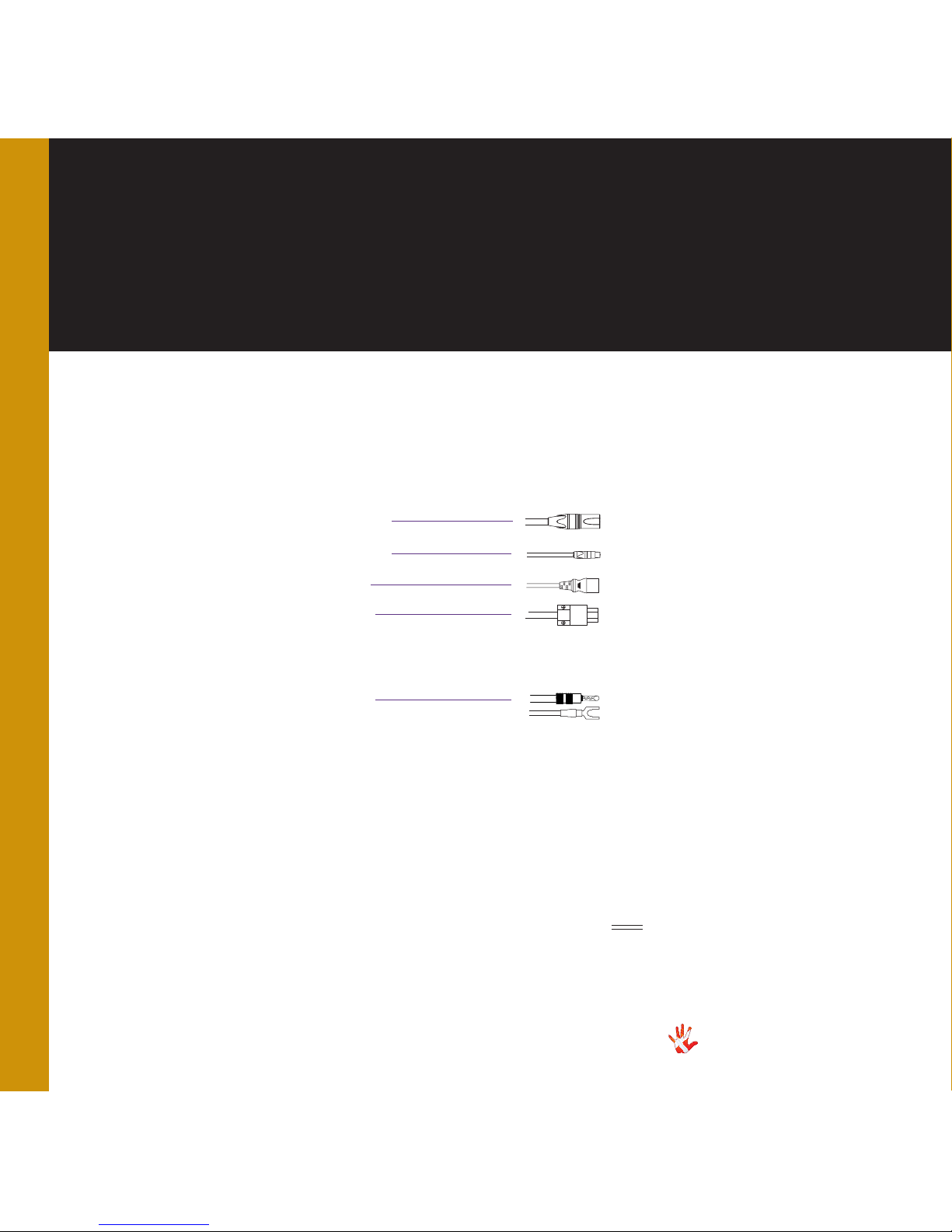
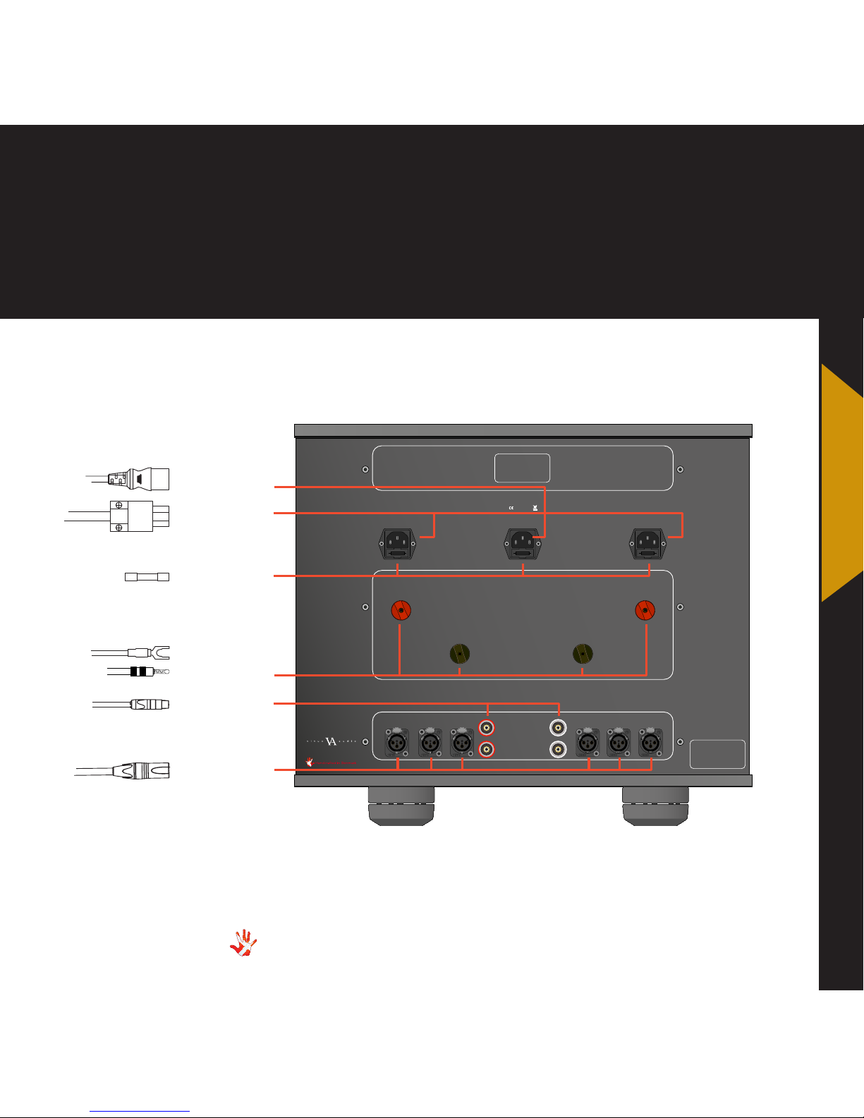
MP-I201 rear panel: Plugs
MP-I201 Inputs.
Input 1,2,3. XLR
Input 4,5. RCA
Digital Power
Analog Power
MP-I201 Outputs
Speakers
Speaker out
Standard Power Cable
Andromeda Power Cable
XLR in
RCA in
Master Piece Series
MP-I201
NEUTRIK
PUSH
NEUTRIK
PUSH
NEUTRIK
PUSH
NEUTRIK
PUSH
NEUTRIK
PUSH
NEUTRIK
PUSH
Right Channel
HQ PC should be used
Left Channel
HQ PC should be used
Digital Control
Standard PC should be used
Input 5 Input 5Input 4 Input 4Input 3 Input 3
Input 2
Input 1
Input 2
Input 1
Preamplier Input
- -
+ +
Serienummer
her
This is a true balanced
poweramplier. DO NOT
under any circumstance
connect (-) speaker output
to ground.
Caution
Warning
To prevent re and shock
hazard, do not expose this device
to rain and moisture
Warning
Risk of electrical shock
DO NOT OPEN
No user serviceable parts inside
MAINS
RCA in
MP-I201 Rearpanel.
Speakers
Digital Power
Analog Power
XLR
13
MP-S201| Version 1
2. connecting
Fuse
2. connecting
MP-I201 rear panel Picture

14
MP-S201 | Version 1
3. operation
MP-I201 Front panel.
Class A/AB
MENU SELECT
STANDBY
MUTE
MP-I O

15
MP-S201| Version 1
3. operation
The MP-I201 has 3
operation modes
1.Normal mode.
This is the mode you use when
listening to music.
2. Menu mode
In this mode you can alter the
settings of the MP-I201.
3. Standby mode.
In this mode the controls of
the MP-I201 are deactivated.
The MP-I201 does not shut
down in Standby Mode in
order to maintain an optimal
working temperature
Operation modes
3. operation

16
MP-S201 | Version 1
Normal mode
In normal mode there are
3 basic functions/buttons
available on the left front.
1. CLASS A/AB
Selects between
the 5 inputs..
2. MENU Switches to
Menu mode.
3. STANDBY Switches in and
out of Standby
Mode
Menu mode
You enter menu mode, by
pushing the ”MENU” button
once in Normal mode. In the
Menu mode there are 3 basic
functions/buttons:
1. Scroll forward in the
menu.
2. MENU/ Enter & Exit
SELECT submenus and
select settings.
3. Scroll backward in the
menu.
Functions – left front panel
Class A/AB
MENU SELECT
STANDBY
MUTE
MP-I O
MP-I201 Left Front panel.

17
MP-S201| Version 1
Functions – right front panel
Class A/AB
MENU SELECT
STANDBY
MUTE
MP-I O
MP-I201 Right front panel.
Normal mode
In normal mode there are
3 basic functions/buttons
available on the right front:
1. Turns volume UP.
2. MUTE Mutes the output.
3. Turns volume DOWN.
Menu mode
In the text-menu it is possible
to change the name of the
input. This is done by using
the following buttons from the
right front:
1. Change selected
character.
2. MUTE Go to the next
character
in the display.
3. Change selected
character.
3. operation

18
MP-S201 | Version 1
3. operation
SETUP
Change the settings of the MP-I201.
CLASS
Select if the MP-I201 should
operate as a Class A or Class AB
amplifier.
OUT.M
Choose between output modus
CLASSIC and ROCK
TEMP.M
Shows the temperature inside the
MP-I201. LT1 LT2
DATA
Shows information about this
MP-D201.
RESET
Restore the settings of the MP-I201
to its default settings.
V.INIT
Change the initial dB step of the
volume in the MP-I201 to any step
between -99 and12.dB
VOL.STEP
The MP-I201 has a standard volume
step of -42 dB. You can set the volume
step to a step, between -99.0 dB
to +6dB.This step will be the new
volume step. Even when after the
power cord has been disconnected
the MP-I201 still starts up in the new
volume step.
REMEMBER
Set the MP-I201 to remember the
current volume step. The MP-I201
will start up in this volume step when
it leaves standby. This volume step
however is not remembered when the
power cord is removed. Then the MPI201 will initiate in the volume step as
it is defined in the V.INIT sub-menu.
BRIGHT
Change the brightness of the display
any step between 0 and 3.
OUT.M
Select between STEREO or MONO
output.
INPUTS
Change settings for each input.
INPUT X
Change the settings of input X.
USED
Select whether input X has to be
USED or not NOT USED.When you
select NOT USED input X will not be
shown in the list of inputs.
FIXED
Lock and unlock the volume by switching
between FIX ON/FIX OFF.
SET FIX
Set the volume of input X to a fixed
dB step. (Input X is now locked to a dB
step and can not be adjusted with the
volume control)
ADJUST
Adjust the fixed dB step to any
step between -99 and +12 dB. This
function is only available when FIX ON
is selected.
OFFSET
Select an offset- gain, between -12
and 12 dB, for input X. This function
is only available when FIX OFF is
selected
SENS
Change the sensitivity of the input.
Select between ≤ 2 Vrms, ≤ 4 Vrms
and ≤ 8 Vrms. The sensitivity level
needs to be higher then the input
level. To prevent clipping of the input
TEXT
Choose a name for input X.
MP-I201 discription of the elements in the menu.

19
MP-S201| Version 1
3. operation
3. operation
MP-I201 menu structure
RESET NO / RESET YES
Right CH
Left CH
RESET
BACK
SETUP
0 / 1 / 2 / 3BRIGHT
OUT.M
BACK
BACK
CLASSIC / ROCK
CLASSIC / ROCK
TEMP.M
Change the
temperature scale
by pressing the
MUTE button
The MP-I201
will count down
from 60 to 0 and
restart, after
modus change
from CLASSIC to
ROCK or ROCK
to CLASSIC.
**
**
*
*
*
ºF/ ºC
LT1 / LT2 / RT1 / RT2
DATA
LEAVE
A / AB
CLASS
INPUT 2
INPUT 3
INPUT 4
INPUT 5
BACK
USED / NOT USED
USED
BACK
INPUT 1
-99 dB / +12 dB
ADJUST
FIX ON / FIX OFF
SET FIX
BACK
-12 dB / +12 dB
8 Vmrs / 2 Vmrs
OFFSET
SENS
TEXT
FIXED
INPUTS
****
****
***
***
BACK
REMEMBER
VOL.STEPV.INIT
-99 dB / +6 dB
With FIX OFF
With FIX ON

20
MP-S201 | Version 1
4. operation & service
Safety notice
The Vitus Audio MP-I201
contains no user serviceable
parts except from the mains
fuse. Do not attempt to open
the case. There are potentially
dangerous voltages present
inside. Should your MP-I201
show signs of malfunction,
then please contact your
dealer or Vitus Audio.
Mains supply voltage
Any unit may be set for
operation in 100V, 115V or
230V A.C. Units are shipped
set for the mains supply
voltage according to the
destination. The voltage
setting can be updated later
by your dealer, if necessary.
Maintenance
Vitus Audio products are
designed to run for many years
without the need for regular
maintenance. Our products
contain no user serviceable
parts except from the mains
fuse. Should your MP-I201
show signs of malfunction,
please contact your dealer or
Vitus Audio.

21
MP-S201| Version 1
4. operation & service
Mains fuse
The mains fuse is accessible
from the outside of the
amplifier. You will find the
mains fuse, just below the
power inlet. If the fuse blows,
then you can easily replace
it. The fuse only blows on the
occurrence of power surges
or if there is a fault in the
unit. Normally power surges
cause no other damage other
than blowing the fuse. When
the fuse blows repeatedly on
replacement, then the unit
most likely has a malfunction.
In case of malfunction the
unit must be returned to Vitus
Audio for repair.
Fuse type:
Left and Right Channel:
230V : 20x5mm 6,3A T
115V : 20x5mm 10A T
100V : 20x5mm 12A T
HRC fuse
Digital Control:
230V : 20 x 5mm – 500mA – T
LBC fuse (Time lag fuse)
100-120V : 20 x 5mm – 1 A – T
- LBC fuse (Time lag fuse)
Replacing the fuse with a fuse
of a type and rating different
from the original fuse, might
result in damage to the unit
and injury to you (the user).
Damage to the unit as a result
of wrongly replacing the
mains fuse, will invalidate the
guarantee.
For an explanation of how to
replace the fuse see chapter 4
“replacing a blown fuse”.
4. operation &
service

22
MP-S201 | Version 1
4. operation & service
REMOVE THE POWER CABLE
In the following steps we will
show you how to replace a
blown fuse.
Different fuse types
The fuses in the Left (L) and
Right (R) Channel are stronger
than the fuse in the digital(D)
control. Do not replace the L
and R fuses with a D fuse, or
the other way around.
See ‘Fuse Type’ for the correct
fuse.
4 Remove the blown fuse and
take the spare fuse.
6 Click the fuse in place.
7 Push the fuse carrier in place.
Replacing a blown fuse
3 There is a spare fuse
available in the fuse carrier.
spare fuse
blown fuse
2 Take a small flat bladed
screwdriver and place it over
the fuse carrier.
1 The fuse carriers are placed
on the back under the power
connectors.
5 Place the spare fuse in the
fuse carrier after you removed
the blown fuse.
L
R
D

23
MP-S201| Version 1
5. warranty
Warranty
Warranty Statement
(modified to fit Vitus Audio)
1. TERMS AND CONDITIONS
LIMITED WARRANTY
Vitus Audio warrants the
product designated herein
to be free of manufacturing
defects in material and
workmanship, subject to the
conditions hereinafter set
forth, for a period of three
(3) years from the date of
purchase by the original
purchaser or no later than
five (5) years from the date of
shipment to the authorized
Vitus Audio cooperating
partner, whichever comes first,
excepting
any cosmetic damage to
chassis parts. (See 6)
2. CONDITIONS
This Warranty is subject to
the following conditions and
limitations. The Warranty
is void and inapplicable
if the product has been
used or handled other than
in accordance with the
instructions in the owner’s
manual, abused, or misused,
damaged by accident
or neglect or in being
transported, or the defect
is due to the product being
repaired or tampered with by
anyone other than Vitus Audio
or authorized Vitus Audio
repair center. The product
must be packed in its original
box and returned to Vitus
Audio or an authorized repair
center by the customer at his
or her sole expense. Vitus
Audio will pay return freight of
its choice.
IMPORTANT!
A returned product MUST
be accompanied by a written
description of the defect
and a photocopy of the
original purchase receipt.
This receipt must clearly list
model and serial number,
date of purchase, the name
and address of the purchaser
and authorized dealer and the
price paid by the purchaser.
Vitus Audio reserves the right
to modify the design of any
product without obligation
to purchasers of previously
manufactured products
and to change the prices or
specifications of any product
without notice or obligation to
any person.
3. REMEDY
In the event the above
product fails to meet the
above Warranty and the above
conditions have been met, the
purchaser’s sole remedy under
this Limited Warranty shall be
to return the product to Vitus
Audio or an authorized Vitus
Audio repair center where the
defect will be rectified without
charge for parts and labor,
except chassis parts. (See 6)
4. LIMITED TO ORIGINAL
PURCHASER
This Warranty is for the
sole benefit of the original
purchaser of the covered
product and shall not be
transferred to a subsequent
purchaser of the product.
5. DURATION OF WARRANTY
This Warranty expires on the
third (3rd) year anniversary
of the date of purchase or
no later than the fifth (5th)
anniversary of the date of
shipment to the authorized
Vitus Audio cooperating
5. warranty

24
MP-S201 | Version 1
5. warranty
partner, whichever comes first.
6. CHASSIS
Damage or cosmetic defects
are not warranted.
7. DEMONSTRATION
EQUIPMENT
Equipment used by an
authorized cooperating
partner for demonstration
purposes is warranted to be
free of manufacturing defects
in materials and workmanship
for a period of three (3) years
from the date of shipment to
the authorized cooperating
partner. After the first year,
demo equipment needing
warranty service must be
packed in its original box
and returned to Vitus Audio
by the cooperating partner
at his or hers sole expense.
Vitus Audio will pay return
freight of its choice. A returned
product must be accompanied
by a written description
of the defect on a VITUS
AUDIO RETURNED GOODS
AUTHORIZATION form.
Dealer-owned demonstration
equipment sold at retail
within three (3) years of date
from shipment to the dealer
is warranted to the first
retail customer to be free
of manufacturing defects in
materials and workmanship
for the duration of the three
(3) Year Limited Warranty
remaining (as measured
from the date of shipment of
the equipment to the Vitus
Audio partner. In the event
warranty service is needed
under these conditions, the
owner of the equipment
must provide a copy of his
purchase receipt, fulfilling the
requirements described under
”2. Conditions” above. The
product must be packed in its
original box, and returned to
Vitus Audio or an authorized
Vitus Audio repair center by
the customer at his or her sole
expense. Vitus Audio will pay
return freight of its choice.
8. MISCELLANEOUS
Any implied warranties relating
to the above product shall be
limited to the duration of this
warranty. The warranty does
not extend to any incidental
or consequential costs or
damages to the purchaser.
Some countries do not allow
limitation on how long an
implied warranty lasts or
exclusion or limitation of
incidental or consequential
damages, so the above
limitations or exclusions may
not apply to you. This warranty
gives you specific legal rights,
and you may also have other
rights which vary from country
to country.
9. WARRANTOR
Inquiries regarding the above
Limited Warranty may be sent
to the following
address:
AVA Group A/S
Sandgaardsvej 31, Birk
DK7400 Herning
Denmark
Att.: Customer Service

25
MP-S201| Version 1
5. warranty
10. WARRENTY OUTSIDE
DANMARK
Vitus Audio has authorized
distribution in many countries
in the world. In each country,
the authorized importing
retailer or distributor has
accepted the responsibility
for warranty of products sold
by that retailer or distributor.
Warranty service should
normally be obtained from the
importing retailer or distributor
from whom purchased your
product. In the unlikely
event of service required
beyond the capabilities of
the importer, Vitus Audio will
fulfill the conditions of the
warranty. Such products must
be returned at the owner’s
expense to the Vitus Audio
factory, together with a
photocopy of the bill of sale
for that product, a detailed
description of the problem,
and any other information
necessary return shipment. In
many cases the retailer your
purchased the product from,
will handle this for you.
11. FURTHER INFORMATION
Should you have any further
questions related to our
warranty – please contact us at
the following email:
info@vitusaudio.com
5. warranty

MP-I201 Specifications
26
MP-S201 | Version 1
6. specications
INPUT
MENU SELECT
STANDBY
MUTE
Front panel and body:
Anodized Aluminium
Feet: Still Point Ultra-5
Total weight: ~125 KG
400 mm
430 mm
708 mm
675 mm
505 mm
500 mm 370 mm
46 mm

MP-I201 Specifications
27
MP-S201| Version 1
6. specications
INPUT
XLR RCA
Available 3 2
Sensitivity 0,7 V
rms
0,7 V
rms
Impedance 10KΩ 10KΩ
POWER
CONSUMPTION
Standby <1W
Full Power 550W
RMS
OUTPUT
Speaker
Right
Speaker
Left
Available 1 1
Impedance 75 mΩ 75 mΩ
Power W (8/4 ohm) 700/1400 700/1400
Frequency response +800kHz +800kHz
Signal to noise ratio > 130dB > 130dB
THD + noise > 0,01% > 0,01%
6. specifications

28
MP-S201 | Version 1
7. examples operation
Example 1
Setting the MP-I201 to
operate as a class AB
amplifier.
Press the“MENU”button to
enter Menu Mode.
Navigate to the CLASS
submenu, using the function
buttons on the left front
1. Scroll forward in
the menu.
2. MENU/ Enter & Exit
SELECT submenus and
select settings.
3. Scroll backward
in the menu.
Enter the CLASS submenu.
The display now shows CLASS
. Press the button. The
display now shows CLASS AB.
Press the SELECT button. The
MP-I201 have operates as a
class AB amplifier.
MENU
LEAVE
SETUP
CLASS
CLASS A
CLASS AB
CLASS
SELECT
SELECT
Figure 6 MP-I201 Left front panel.
INPUT
MENU
SELECT
STANDBY
MUTE
SIA
5

29
MP-S201| Version 1
7. examples operation
Class A/AB
MENU SELECT
STANDBY
MUTE
MP-I O
MP-I201 Left Front panel.
The MP-I201
will count down
from 60 to 0 and
rerestart, after
modus change
from CLASSIC to
ROCK or ROCK
to CLASSIC.
*
Example 2
Setting the Right and
Left channel of the MPI201 to play in ROCK
modus.
Press the“MENU”button to
enter Menu Mode.
Navigate to the OUT.M
submenu, using the function
buttons on the left front
1. Scroll forward in
the menu.
2. MENU/ Enter & Exit
SELECT submenus and
select settings.
3. Scroll backward
in the menu.
Enter the OUT.M submenu.
Change CLASSIC to ROCK for
both channels, and leave the
menu. The MP-I201 now counts
down from 60 to 0 and restarts.
LEAVE
SETUP
BACK
OUT.M
RIGHT CH
CLASSIC
ROCK
RIGHT CH
LEFT CH
CLASSIC
ROCK
LEFT CH
BACK
OUT.M
SELECT
SELECT
SELECT
SELECT
SELECT
SELECT
SELECT
MENU
6O
59 5
8........
7. examples

Example 3
Restoring the settings
of the MP-I201
Press the MENU button to
enter Menu Mode.
Navigate to the RESET
submenu, using the function
buttons on the left front
1. Scroll forward in
the menu.
2. MENU/ Enter & Exit
SELECT submenus and
select settings.
3. Scroll backward
in the menu.
Enter the RESET submenu.
The display now shows RESET
NO. Press the button. The
display now shows RESET YES.
Press the SELECT button. The
settings of the MP-I201 have
now been restored.
The MP-I201 now automatically
goes into standby mode.
Class A/AB
MENU SELECT
STANDBY
MUTE
MP-I O
MP-I201 Left Front panel.
30
MP-S201 | Version 1
7. examples operation
MENU
LEAVE
SETUP
BACK
OUT.M
TEMP.M
DATA
RESET
RES:NO
RES:YES
SELECT
SELECT
SELECT

Class A/AB
MENU SELECT
STANDBY
MUTE
MP-I O
MP-I201 Left Front panel.
Example 4
Setting the
initial volume step.
Press the“MENU”button to
enter Menu Mode.
Navigate to the V.INIT
submenu, using the function
buttons on the left front
1. Scroll forward in the
menu.
2. MENU/ Enter & Exit
SELECT submenus and
selectsettings.
3. Scroll backward in
the menu.
In the V.INIT submenu you
can adjust the initial volume
step. This is the volume step
the MP-I201 starts up in when
it leaves standby mode. The
initial volume step is as a
standard set to -40.
Set the volume step to -30
using the and the
buttons. Press SELECT and
leave the menu.
MENU
LEAVE
SETUP
BACK
OUT.M
TEMP.M
DATA
RESET
V.INIT
VOL.STEP
- O.O
- O.O
VOL.STEP
SELECT
SELECT
SELECT
Next time you turn on the
MP-I201, it will initialize in
volume step -30 dB.
31
MP-S201| Version 1
7. examples operation
7. examples

Example 5
Setting the MP-I201
to remember the current volume step.
Press the“MENU”button to
enter Menu Mode.
Navigate to the V.INIT
submenu, using the function
buttons on the left front
1. Scroll forward in the
menu.
2. MENU/ Enter & Exit
SELECT submenus and
selectsettings.
3. Scroll backward in
the menu.
In the V.INIT submenu you can
set the MP-I201 to remember the
current volume step. The MPI201 will start up in this volume
step when it leaves standby.
This volume step however is not
remembered when the power
cord is removed. Then the MPI201 will initiate in the volume step
as it is defined in the V.INIT submenu (example 9).
Go to REMEMBER press SELECT.
The display now shows VOL.INIT.
The MP-I201 will now start up in the
current volume step on initialization.
Class A/AB
MENU SELECT
STANDBY
MUTE
MP-I O
MP-I201 Left Front panel.
LEAVE
SETUP
BACK
OUT.M
TEMP.M
DATA
RESET
V.INIT
VOL.STEP
REMEMBER
V.INIT
SELECT
SELECT
SELECT
MENU
32
MP-S201 | Version 1
7. examples operation

Example 6
Changing brightness
from 1 to 2.
You can adjust the brightness
of the display.
Press the“MENU”button to
enter Menu Mode.
Navigate to the
“BRIGHTNESS” submenu,
using the function buttons on
the left front
1. Scroll forward in
the menu.
2. MENU/ Enter & Exit
SELECT submenus and
select settings.
3. Scroll backward
in the menu.
Enter the “BRIGHTNESS”
submenu The display now
shows “1”. Press the “”
button. The brightness is now
set to 2. Press “SELECT” to
leave the. “BRIGHTNESS”
submenu.The new brightness
level is now saved.
Class A/AB
MENU SELECT
STANDBY
MUTE
MP-I O
MP-I201 Left Front panel.
MENU
LEAVE
SETUP
BACK
OUT.M
TEMP.M
DATA
RESET
V.INIT
BRIGHT
1
2
BRIGHT
SELECT
SELECT
SELECT
33
MP-S201| Version 1
7. examples operation
7. examples

Figure 12 Example 6 RP-101
LEAVE
SETUP
BACK
OUT.M
TEMP.M
DATA
RESET
V.INIT
BRIGHT
INPUTS
INPUT1
INPUT2
INPUT
3
INPUT
4
USED
USED
NOT USED
USED
SELECT
SELECT
SELECT
SELECT
MENU
SELECT
Class A/AB
MENU SELECT
STANDBY
MUTE
MP-I O
MP-I201 Left Front panel.
34
MP-S201 | Version 1
7. examples operation
Example 7
Disabling inputs.
If you only use some of the
inputs,then it is possible to
disable the inputs that you are
not using. The system will skip
the disabled inputs,
and jump to the next input.
The following example
illustrates how to disable
Input 4.
Press the“MENU”button to
enter Menu Mode.
Navigate to the INPUT submenu, using the function
buttons on the left front
1. Scroll forward in the
menu.
2. MENU/ Enter & Exit
SELECT submenus and
selectsettings.
3. Scroll backward in
the menu.

Class A/AB
MENU SELECT
STANDBY
MUTE
MP-I O
MP-I201 Left Front panel.
LEAVE
SETUP
BACK
OUT.M
TEMP.M
DATA
RESET
V.INIT
BRIGHT
INPUTS
INPUT1
USED
BACK
FIXED
SET FIX
FIX OFF
FIX ON
SET FIX
ADJUST
-1.O
O.O
ADJUST
BACK
SELECT
SELECT
SELECT
SELECT
SELECT
SELECT
SELECT
SELECT
MENU
35
MP-S201| Version 1
7. examples operation
Figure 22 Example 12 Changing the input name.
Example 8
Set the volume of
input 1 to a fixed
volume step of -0.0 dB.
You can set the volume of an
input to a fixed dB step. The input
is then locked to this dB step
and can not be adjusted with the
volume control. The following
example illustrates how to fix
the volume step of Input 1 to
0dB.
Press the“MENU”button to
enter Menu Mode.
Navigate to the INPUT submenu, using the function
buttons on the left front
1. Scroll forward in the
menu.
2. MENU/ Enter & Exit
SELECT submenus and
selectsettings.
3. Scroll backward in
the menu.
Adjust the volume step to -0.0 dB
and press the SELECT button. The
display now shows SET FIX.
Input X is now locked to the
chosen dB step and can not be
adjusted with the volume control.
If you want to set FIX OFF, then
repeate the sequence of the
example and select FIX OFF.
7. examples

Class A/AB
MENU SELECT
STANDBY
MUTE
MP-I O
MP-I201 Left Front panel.
LEAVE
SETUP
BACK
OUT.M
TEMP.M
DATA
RESET
V.INIT
BRIGHT
INPUTS
INPUT1
INPUT
USED
BACK
FIXED
OFFSET
O.O
- .O
- .O
- .O
OFFSET
SELECT
SELECT
SELECT
SELECT
SELECT
SELECT
SELECT
SELECT
MENU
36
MP-S201 | Version 1
7. examples operation
Example 9
Changing the offsetgain of the inputs.
You can set different offsetvalues for the different inputs.
You actually adjust the gain
of one individual input. This
reduces the differences in
output volume, when you
switch from one input to
another. The offset-value can
be set from -12 dB to +12 dB.
You cannot change the offset
gain with FIX ON selected.
The following example
illustrates how to change the
offset-values: The signal on
the source using line 2 is 3 dB
higher than the signal on the
source using line 1.
We will reduce the differences
in volume between input 1 and
input 2 by lowering the offset
gain of line 2 with 3 dB.
Press the“MENU”button to
enter Menu Mode.
Navigate to the INPUT submenu, using the function
buttons on the left front
1. Scroll forward in the
menu.
2. MENU/ Enter & Exit
SELECT submenus and
selectsettings.
3. Scroll backward in
the menu.
The amplifier now automatically
turns the volume up or down
when you change between
inputs.

Class A/AB
MENU SELECT
STANDBY
MUTE
MP-I O
MP-I201 Left Front panel.
LEAVE
SETUP
BACK
OUT.M
TEMP.M
DATA
RESET
V.INIT
BRIGHT
INPUTS
INPUT1
USED
BACK
FIXED
OFFSET
SENS
Vrms
Vrms
SENS
SELECT
SELECT
SELECT
SELECT
SELECT
MENU
37
MP-S201| Version 1
7. examples operation
Example 10
Changing the sensitivity of input 1 from
8 V rms to 4 V rms
The sensitivity is as a standard
set to 4 Vrms.
In this example we will change
the sensitivity of input 1 from 4
Vrms to 2 Vrms.
Press the“MENU”button to
enter Menu Mode.
Navigate to the SENS
submenu, using the function
buttons on the left front
1. Scroll forward in the
menu.
2. MENU/ Enter & Exit
SELECT submenus and
selectsettings.
3. Scroll backward in
the menu.
In the SENS submenu you can
adjust the sensitivity using the
and the buttons. When
you adjusted the sensitivity
press SELECT. The new
sensitivity is now saved.
2
4
7. examples

LEAVE
SETUP
BACK
OUT.M
TEMP.M
DATA
RESET
V.INIT
BRIGHT
INPUTS
INPUT1
USED
BACK
FIXED
OFFSET
SENS
TEXT
LINE
SCD-O2
5
TEXT
SELECT
SELECT
SELECT
SELECT
SELECT
SELECT
SELECT
MENU
Class A/AB
MENU SELECT
STANDBY
MUTE
MP-I O
MP-I201 Left Front panel.
MENU
38
MP-S201 | Version 1
7. examples operation
Example 11
Changing the name of
INPUT 1 to SCD-010.
Press the“MENU”button to
enter Menu Mode.
Navigate to the TEXT
submenu, using the function
buttons on the left front
1. Scroll forward in the
menu.
2. MENU/ Enter & Exit
SELECT submenus and
selectsettings.
3. Scroll backward in
the menu.
In the TEXT submenu you
will find a list of predefined
names, that you can choose
from.
Scroll through the list using
the and the buttons.
Select the name SCD-010
using the SELECT button.
The name of INPUT1 has now
been changed from LINE 1 to
SCD-010.
Leave the TEXT submenu.
When you leave the Menu
Mode the display will show
SCD-010.

Class A/AB
MENU SELECT
STANDBY
MUTE
MP-I O
MP-I201 Right Front
39
MP-S201| Version 1
7. examples operation
Example 12
Changing the name
of INPUT 1 to PICKUP
If you want to use an inputname that is not in the
predefined list, then it is
possible to manually add a
name to the list.
In the text- menu it is possible
to change the name of the
input. This is done by using
the following buttons from the
right front:
1. Change selected
character.
2. MUTE Go to the next
character in the display.
3. Change selected
character..
We will now change the inputname “Line 1” to PICKUP
(Not in the predefined list) .
We continue from the “TEXT
” sub-menu in the previous
example.
LINE
.INE
PINE
P.NE
PI.E
PICE
PIC.
PICK
PICK.
PICKU
PICKU.
PICKUP
TEXT
MUTE
MUTE
MUTE
MUTE
MUTE
MUTE
MUTE
MENU
The display is showing LINE 1
Press MUTE
(The first character in the
display starts blinking)
Press or until the first
character has the value you
want. Press MUTE (The second
character in the display starts
blinking)
Press MUTE when the last
character in the display is
blinking. The new device name
is now saved, and then you can
leave the TEXT sub-menu.
When you are editing the Input
name, then you can save the
changes at any time. You do
this by pressing the SELECT
button
7. examples

40
MP-S201 | Version 1
7. examples connecting devices
Connecting devices 1
We have an MP-L201 as
linestage. The MP-L201
is connected to an MPD201 and a MP-P201. The
MP-D201 is connected to
an MP-T201 a PC and a
Mediacenter. The MP-P201 is
connected to a Turntable.
Units
Vitus Audio products
Signature Series
MP-L201
MP-P201
MP-D201
MP-T201
MP-I201
3rd. party products
Turntable
PC
Media Center
Speakers
MP-P201
Turntable
MP-D201
Media Center
PC
MP-T201
MP-I201

41
MP-S201| Version 1
7. examples connecting devices
Connecting devices 2
We have an MP-L201 as
linestage. The MP-L201
is connected to an MPD201 and a MP-P201. The
MP-D201 is connected to
an MP-T201 a PC and a
Mediacenter. The MP-P201 is
connected to a Turntable.
The MP-I201 are set to
function as a Mono Amplifier.
Units
Vitus Audio products
Signature Series
MP-L201
MP-P201
MP-D201
MP-T201
MP-I201
3rd. party products
Turntable
PC
Media Center
Speakers
MP-L201
MP-P201
Turntable
MP-D201
Media Center
PC
MP-T201
MP-I201
MP-I201
7. examples

Picture 2 MP-I201 Front
42
MP-S201 | Version 1
8. pictures
MP-I201 Front

43
MP-S201| Version 1
8. pictures
MP-I201 Inside
8. pictures

Handcrafted in Denmark
vitus audio
AVA Group A/S (Vitus Audio), Dueoddevej 6B (Administration) Hammershusvej 3H (Shipping)
DK-7400 Herning, Denmark, Phone: +45 9626 8046, Fax: +45 9626 8045
e-mail: info@vitusaudio.com, web site: www.vitusaudio.com
 Loading...