


HOME CONTROL
EN
INSTALLATION and OPERATION
Vitrum Scene Control Panel

DESCRIPTION
A Vitrum Scene differs from Dimmer and
On-Off devices for this reason: there
is no exit used for directly control a load.
It’s used for creating lighting scenarios in
your house: simply pressing a button, you
can switch on and off (in case of lamp
connected to a Vitrum dimmer you can
select the light level too) the lights of your
scenary.
.
INDEX
0. Before starting ................ 3
1. Electrical connections ........... 4
2. Positioning the glass decor panel . . 6
3. Vitrum is intelligent . . . . . . . . . . . . . 8
4. Advanced functions ........... 11
5. Factory Reset ................ 14
7. Supervision .................. 16
8. Compatibility ................ 17
9. Compliance with ec directives . . 17
MAIN TECHNICAL SPECIFICATIONS
. . 18

3
0. BEFORE STARTING
The Vitrum system that you have purchased is designed for connection to your existing
240V power supply circuit. Before commencing installation, ensure that the mains power
supply had been disconnected by setting the main switch on your electricity meter to
OFF
. Do not re-connect the power supply and start using Vitrum until all connections
have been correctly completed and the Vitrum unit has been inserted into the wallmounting box.
Vitrum must be installed by a professional electrician who is qualified to operate
on electrical power circuits in full compliance with all current safety legislation.
For each device, connect the power supply and the return wire from the actuators as
shown in the circuit diagrams printed on the rear of the boxes in the vicinity of the terminal
block. Refer exclusively to the circuit diagrams contained in this manual, especially if
connecting the system without an earth wire.
Carefully check that the wires and connectors are securely fastened. After
securing the unit to the wall-mounting box, temporarily use the plastic cover
for protection until the glass décor plate is fitted.
Do not install Vitrum in the vicinity of sources of heat or in conditions of high humidity.
4
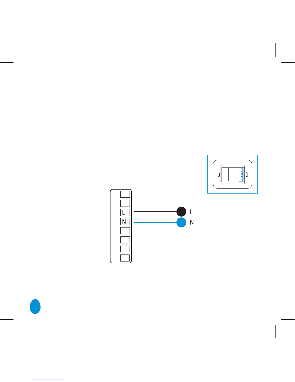
1. ELECTRICAL CONNECTIONS
Electrical connections with neutral wire: connect the Live wire to the terminal marked
“L”, the Neutral wire to the terminal marked “N”:

5
IMPORTANT
After connecting, check that the wires are correctly positioned inside the wallmounting box. When securing Vitrum to the wall-mounting box, use the screws sup-
plied and note that the maximum torque to be used when tightening the screws in
the embedding box is 0.8 Nm. In addition, the surface of the wall for at least 2 cm
surrounding the embedding box MUST BE as flat and smooth as possible, and must not
have any rough patches and/or bumps that protrude more than 1 mm.
If the screws are not tightened with the torque specified, or if the embedding
box is installed on unsuitable surfaces, the correct operation of the device cannot be guaranteed.
Think Simple Spa accepts no liability if the device is not correctly installed as described above.
6
2. POSITIONING THE GLASS DECOR PANEL
In order to refit the glass panel correctly, ensure that the four plastic tabs on the
panel are in perfect alignment with the anchor holes. When the glass panel tabs
are aligned with the holes, press the four corners of the glass panel evenly until it
is fully inserted into the wall-mounting box.
Anchor holes on electronic section

7
After fitting the glass panel, the buttons remain inoperative for about 10 seconds.
An acoustic signal sounds three times to indicate that the sensors have been
recalibrated, after which they resume normal operation. To remove the glass panel
from the wall-mounting box, gently lever the upper or lower edge away.
Anchor holes on décor panel

8
3. VITRUM IS INTELLIGENT
The product that you have purchased functions when included in a Z-Wave wireless net.
Thanks to “Z-Wave” Wireless technology, each Vitrum Wireless unit offers numerous
advantages if connected as part of a network: it is possible to associate multiple Vitrum
units, to construct scenarios, and to control lights using a remote control unit. If you connect
Vitrum into a pre-existing z-wave net working with third parts devices, please refer to
instruction and procedure of your remote control. Otherwise proceed as follows to include
Vitrum to your Home Wireless NETWORK:
Open the rear panel of the • HOME MASTER remote handset.
1A
B
C
D
2
3
4

9
Press and hold down • “INC” until the corresponding LED turns yellow, then
release the button
Place the HOME MASTER remote handset near the Vitrum unit to be included in •
the network. Touch any of the keys on Vitrum to include the unit in the home
wireless network.
Everytime a new device is included into the zwave net, you must include your Vitrum
scene again; during this operation, Vitrum scene will blink of magenta color for few
seconds: wait until it stop to proceed.

10
When all the Vitrum units have been added to the network, press the “INC” •
key again until the LED switches off. Now you will see that the illuminated rings
around the Vitrum touch keys no longer light red when changing from one
status to the next.
NOTE
A Vitrum unit cannot be added to the network if it has already been included
in a different network. In this case, it is necessary to perform the factory reset
procedure -> see Paragraph 7).

11
4. ADVANCED FUNCTIONS: CREATION OF CONTROL LOGIC
On all Vitrum Wireless units, it is possible to create control logic processes that
associate the button on one Vitrum module to other buttons on OTH ER Vitrum
modules For creating a control logic, the modules must first be included in the home
wireless network -> see paragraph 3. It’s very simple to create a scene. First of all you
need to associate your Vitrum Scene to all the other buttons of other Vitrum that you
desire be part of the scene (max 8 Vitrum). So, every time you’ll push a scene (buttons
1,2,3 or 4) you will activate a light level on ALL the Vitrum Buttons associated (for Roller
Blind possible levels are only closed or open).
NOTE
you can associate to a Vitrum scene up to 8 Vitrum
set the HOME MASTER remote handset to • association mode by presssing and
holding down the “ASC” button until the YELLOW LED lights. Then release the
“ASC” button.

12
Press the buttons of the other Vitrum that are physically connected to the lighs you
want to be part of the scene. The LED corresponding to the selected button/channel
will flash magenta until the ‘association’ process has been completed. When finished
press briefly again the “ASC” button of remote control

13
Now press any of Vitrum scene buttons (1,2,3 or 4)
Performing the above steps you have created the association. Now simply set all your
lights’ scenario to the desired level and keep pressed the selected button (1,2,3 or 4)
until it start blinking; then release it.
It will keep blinking for all the time necessary to memorize the lights’ level and, when
finished, it will beep twice. After that , every time you press it, it will set all the light
of your scene to the selected level; pressing again and you will switch all the light off.
Perform the same operation with all Vitrum scene button.
In order to cancel associations that have been entered, simply perform the same
procedure, though pressing the “DIS” key on the HOME MASTER remote handset
instead of “ASC”.

14
5. FACTORY RESET
Proceed as follows to reset the Vitrum unit to the original factory settings:
A.
EXCLUSION from the home network using the HOME MASTER remote han-
dset:
Press • “EXC” on the HOME MASTER remote handset and wait until the
yellow LED lights.
Press and hold down the leftmost button on the multi-channel Vitrum unit (• EU
Standard), or the topmost key (BS Standard) or the central key on singlechannel units, for at least 8 seconds.

15
Vitrum will flash red three times and sound an acoustic signal to indicate •
that the original configuration has been restored.
B. FACTORY RESET using the hidden button
Remove the Vitrum unit from the wall-mounting box.•
Press the hidden Factory Reset button and hold down for at least 3 seconds. •
Vitrum will flash RED three times and sound an acoustic signal to indicate
that the original factory configuration has been restored.

16
7. SUPERVISION (wireless devices only)
If you have decided to activate the HOME MASTER supervision apps for iPad®,
you will find that the “identification” function featured by every Vitrum unit is
extremely useful. “Identification” status is indicated when all the illuminated rings
light Magenta and begin to flash. This functional status is created directly by the
supervision app as soon as the corresponding command is entered.
Download free Home Master App for your iPad® from the Apple Store.

17
8. COMPATIBILITY
All Vitrum Wireless devices are tested and certified to Z-Wave specifications and are
designed to interact with certified Z-Wave products marketed by other manufacturers.
Certified Z-Wave devices of different types or designed for other applications may be added
to your home network; if these support the functions, they can also be used as repeaters
to communicate with your Vitrum wireless units. In this way, your system can easily be
extended to operate with different applications and thus adapted to your specific needs.
9. COMPLIANCE WITH EC DIRECTIVES
All Vitrum Wireless units are built in compliance with the following European
directives: B.T.2006/95/CE, E.M.C.:2004/108/CE, R&TTE:1999/5/CE.
The Manufacturer accepts no liability for any damage or injuries that might be caused
by this product if it is used in any way other than as described in this manual.
Think Simple SpA reserves the right to introduce any modifications that might be
considered useful or necessary and which do not alter the principal characteristics of
the product. Therefore, all the information given in this datasheet is to be considered
subject to possible modifications. For this reason we invite you to check for update
of Vitrum users guide at www.vitrum.com/eng/content/download

18
MAIN TECHNICAL SPECIFICATIONS
Vitrum Scene Control Panel
Power supply
Energy consumption
Operating temperature
(from / to)
Wireless Z-Wave modem
frequency
Range in open air
IP Protection Rating
240V/50Hz
<1 w
0-40° C
868,4 MHz
20 mt
IP 40

19
To discover further functions and products by
VITRUM please visit our site:
www.vitrum.com

Think Simple SpA
Head Office
viale Lino Zanussi, 3 Tel +39 0434 516 216
33170 Pordenone Fax +39 0434 516 230
Sales Office
corso Garibaldi, 86 Tel +39 02 655 600 29
20121 Milano Fax +39 02 454 982 95
www.thinksimple.it info@thinksimple.it
HOME CONTROL
by
I000124 - 07/2012
 Loading...