

Vitrum On-Off Wireless Installation And Operation Manual

HOME CONTROL
EN
INSTALLATION AND OPERATION
Vitrum On-Off Wireless

INDEX
0. Before starting ................ 3
1. Electrical connections ........... 4
2. Positioning the glass decor panel ... 8
3. Vitrum is intelligent ............ 9
4.
Configuration of the type of switch
12
5. Advanced functions ........... 15
6. Factory reset ................. 19
7. Supervision .................. 21
8. Compatibility ................ 22
9. Compliance with ec directives ... 22
MAIN TECHNICAL SPECIFICATIONS
. . 23

3
0. BEFORE STARTING
The Vitrum system that you have purchased is designed for connection to your
existing 230V power supply circuit. Before commencing installation, ensure that the
mains power supply had been disconnected by setting the main switch on your
electricity meter to
OFF. Do not re-connect the power supply and start using Vitrum
until all connections have been correctly completed and the Vitrum unit has been
inserted into the wall-mounting box.
Vitrum must be installed by a professional electrician who is
qualified to operate on electrical power circuits in full compliance
with all current safety legislation.
For each device, connect the power supply and the return wire from the actuators
as shown in the circuit diagrams printed on the rear of the boxes in the vicinity of
the terminal block. Refer exclusively to the circuit diagrams contained in this manual,
especially if connecting the system without an earth wire.
Carefully check that the wires and connectors are securely fastened. After
securing the unit to the wall-mounting box, temporarily use the plastic cover
for protection until the glass décor plate is fitted.
Do not install Vitrum in the vicinity of sources of heat or in conditions of high humidity.
IMPORTANT: Fit a rapid-acting fuse with a high switching capacity that is
suitable for the load applied to the device.
4
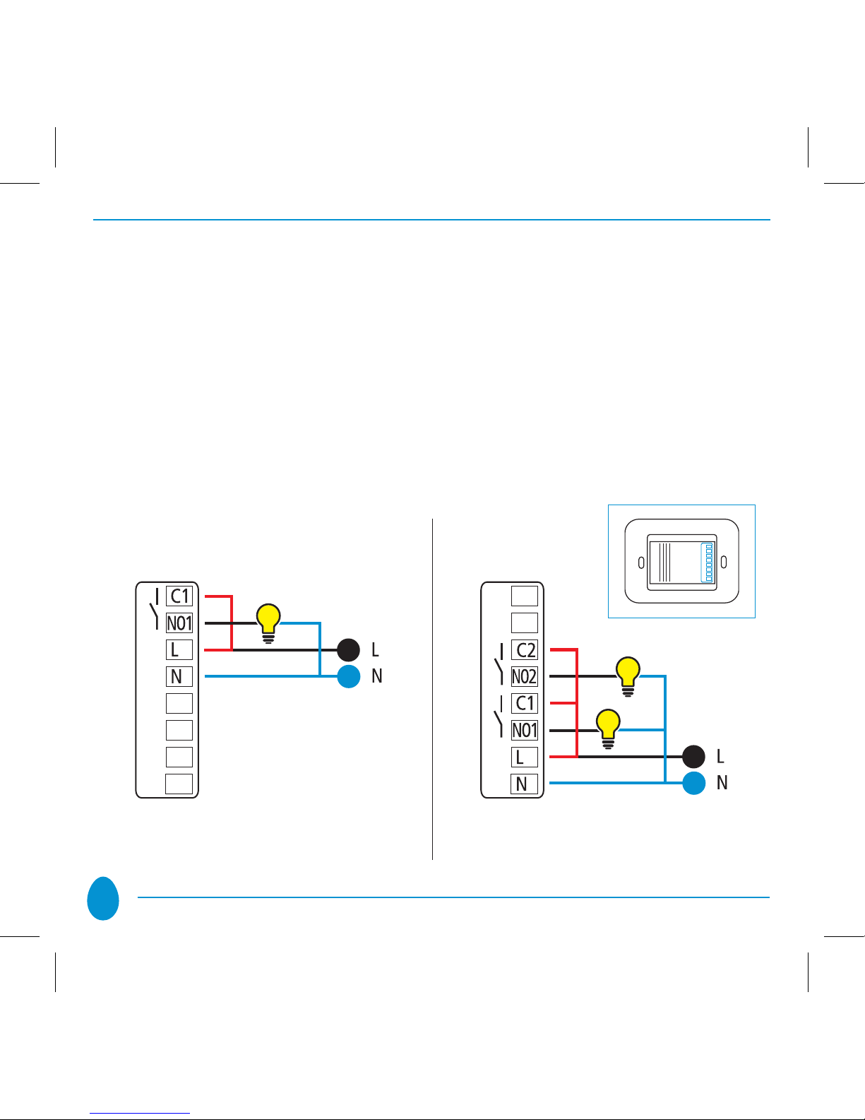
1. ELECTRICAL CONNECTIONS
Simply connect the Live wire to the terminal marked “L”, the Neutral wire to the
terminal marked “N” and the light(s) to the terminal(s) marked “NO1...NO3”.
All the relays function as switches, and the contacts are normally open. The units are
supplied complete with the jumpers marked on the diagram in red for connection
of terminals “C1...C3”. The device may be set to operate as a “Button” as well as
a “Switch”.
On-off Wireless
1 channel EU
On-off Wireless
2 channels EU
5
On-off Wireless
3 channels EU
On-off Wireless
1 channel BS
On-off Wireless
2 channels BS
On-off Wireless
4 channels BS
6
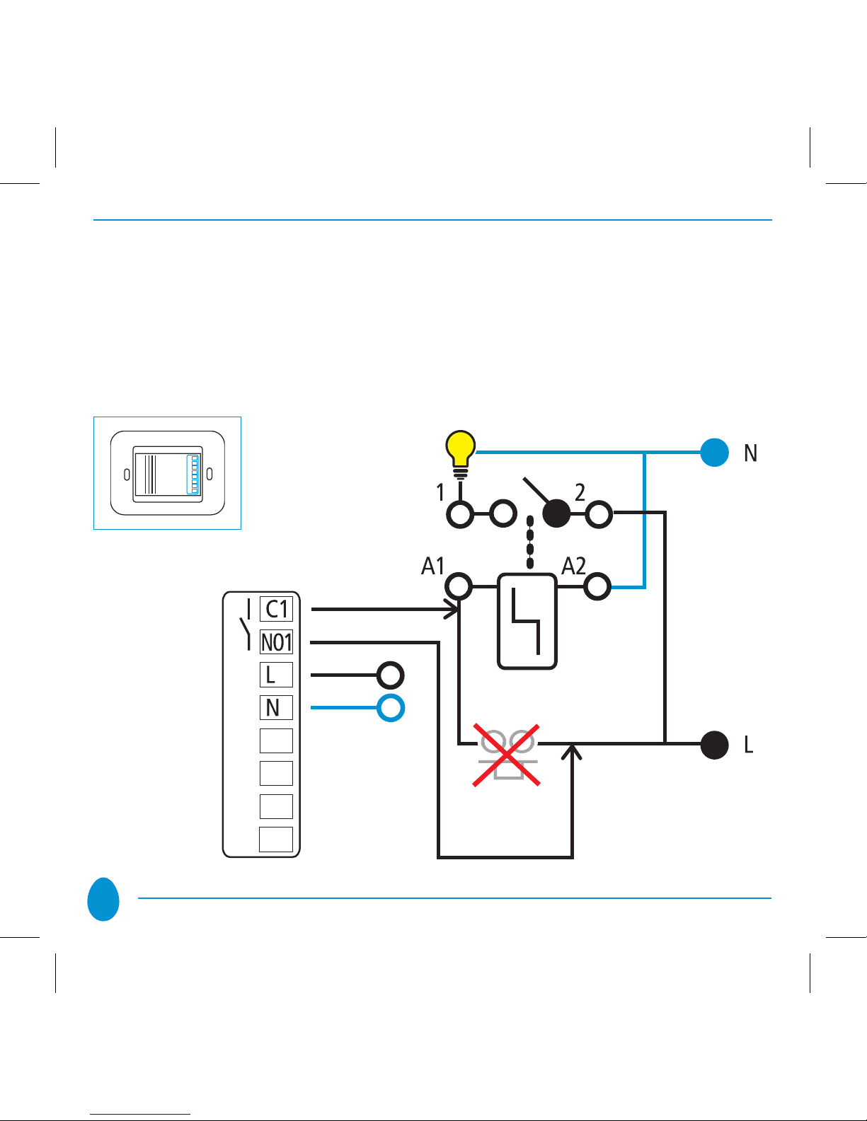
The circuit diagram below shows how to connect without the use of the jumper in
order to replace a button which controls a step relay for control of an existing lighting
system:
Step Relay
Button
to replace

7
IMPORTANT
After connecting, check that the wires are correctly positioned inside the
wall-mounting box. When securing Vitrum to the wall-mounting box, use
the screws supplied but do not use electric screwdrivers, as these may
exert excessive force which might damage the product.
8
2. POSITIONING THE GLASS DECOR PANEL
In order to refit the glass panel correctly, ensure that the four plastic tabs on the
panel are in perfect alignment with the anchor holes. When the glass panel tabs
are aligned with the holes, press the four corners of the glass panel evenly until it
is fully inserted into the wall-mounting box.
After fitting the glass panel, the buttons remain inoperative for about 10 seconds.
An acoustic signal sounds three times to indicate that the sensors have been recalibrated, after which they resume normal operation. To remove the glass panel
from the wall-mounting box, gently lever the upper or lower edge away.
Anchor holes on electronic section Anchor tabs on décor panel
 Loading...