

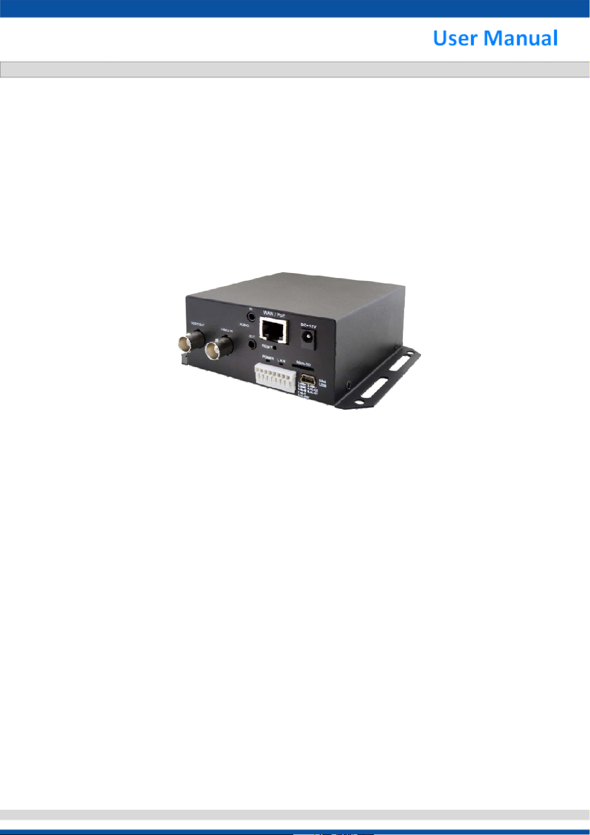
H.264 Video Server (960H)
SNE-1001-E
Thanks for purchasing our product. Before operating the unit, please read the
instructions carefully and keep this manual for future reference.
Safety Warning
1. Read this manual carefully before installing the unit
Please read this manual first for correct installation and operation.
2. Never install the camera on a ceiling that cannot hold its weight
The product may fall down and cause damages.
3. Never install the camera near electric or magnetic fields
Install the camera away from TV, radio transmitter, magnet, electric motor, transformer, audio
speakers since the magnetic fields generate from above devices would distort the video image.
4. Never install or use the camera in areas exposed to water, oil or gas
The water, oil or gas may result in operation failure, electric shock or fire. Do not use this unit
near water-for example, near a bath tub, wash bowl, kitchen sink, or laundry tub, in a wet
basement, near a swimming pool, in an unprotected outdoor installation, or any area which is
classified as a wet location.
5. Never face the camera toward the sun
Direct sunlight or severe ray may cause fatal damage to sensor and internal circuit.
6. Power Cord Protection
Touching the wet power cord with hands or touching the power cord with wet hands may result in
electric shock. Power supply cords should be routed so that they are not likely to be walked on
or pinched by items placed upon or against them, playing particular attention to cords and plugs,
convenience receptacles, and the point where they exit from the appliance.
7. Attachments
Do not use attachment not recommended by the product manufacturer as they may cause
hazards.
8. Object and Liquid Entry
Never push objects of any kind into this product through openings as they may touch dangerous
voltage points or short-out parts that could result in a fire or electric shock. Never spill liquid of
any kind onto the product.
9. Do not operate the camera in environments where the temperature,
humidity or power source is beyond the specified ones
Use the camera in suitable environments where the temperature is within -10°C~50°C and
humidity below 80%. Use the input power source as this instruction indicated.
i
130918-2112TU-F-V2.6-V1
10. Cleaning
Unplug the unit from the outlet before cleaning. Do not use liquid cleaners or aerosol cleaners.
Use a damp cloth for cleaning.
11. Never disassemble the camera nor put impurities in it
Disassembly or impurities may result in trouble or fire.
12. Stop using when the product emits smoke or abnormal heat
13. Servicing
Do not attempt to repair this unit yourself as opening or removing covers may expose you to
dangerous voltage or other hazards. Refer all servicing to qualified service personnel.
14. Retain Instructions
THE SAFETY AND OPERATING INSTRUCTIONS SHOULD BE RETAINED FOR FUTURE
REFERENCE.
NOTE:
The information in this manual was current when published. The manufacturer reserves the right to
revise and improve its products. All specifications are therefore subject to change without notice.
ii
130918-2112TU-F-V2.6-V1

Table of Contents
1. CAMERA................................................................................................................................................................................ 1
1.1 FEATURE........................................................................................................................................................................... 1
1.2 LIST OF CONTENTS ............................................................................................................................................................ 1
1.3 SYSTEM REQUIREMENTS.................................................................................................................................................... 1
1.4 SPECIFICATION.................................................................................................................................................................. 2
1.5 DIMENSIONS...................................................................................................................................................................... 3
1.6 CAMERA OVERVIEW........................................................................................................................................................... 4
1.7 INSTALLATION .................................................................................................................................................................... 5
1. Installation Flow Chart........................................................................................................................................... 5
2. Direct Link ............................................................................................................................................................. 6
3. Link via Hub / PoE Hub ......................................................................................................................................... 6
2. USER INTERFACE................................................................................................................................................................ 7
2.1 LOGIN ............................................................................................................................................................................... 7
2.2 INTERFACE OVERVIEW ....................................................................................................................................................... 8
1. Live View............................................................................................................................................................... 9
2. Video ................................................................................................................................................................... 10
3. Image ...................................................................................................................................................................11
4. Audio ................................................................................................................................................................... 12
5. DateTime............................................................................................................................................................. 13
6. Network ............................................................................................................................................................... 14
7. Alarm................................................................................................................................................................... 16
8. Storage................................................................................................................................................................ 17
9. Maintain............................................................................................................................................................... 18
10. PTZ/OSD........................................................................................................................................................ 19
iii
130918-2112TU-F-V2.6-V1
1. CAMERA
1.1 Feature
H.264, MPEG4, M-JPEG Video Compression
Resolution up to 960H
Meets RoHS Directive
Support LAN & WAN (PPPoE)
Support Triple Streaming
Digital Time Code Embedded
Motion Detection
Isolated Digital Input and Output Supported
Two-way Audio
1.2 List of Contents
Video Server unit
User manual
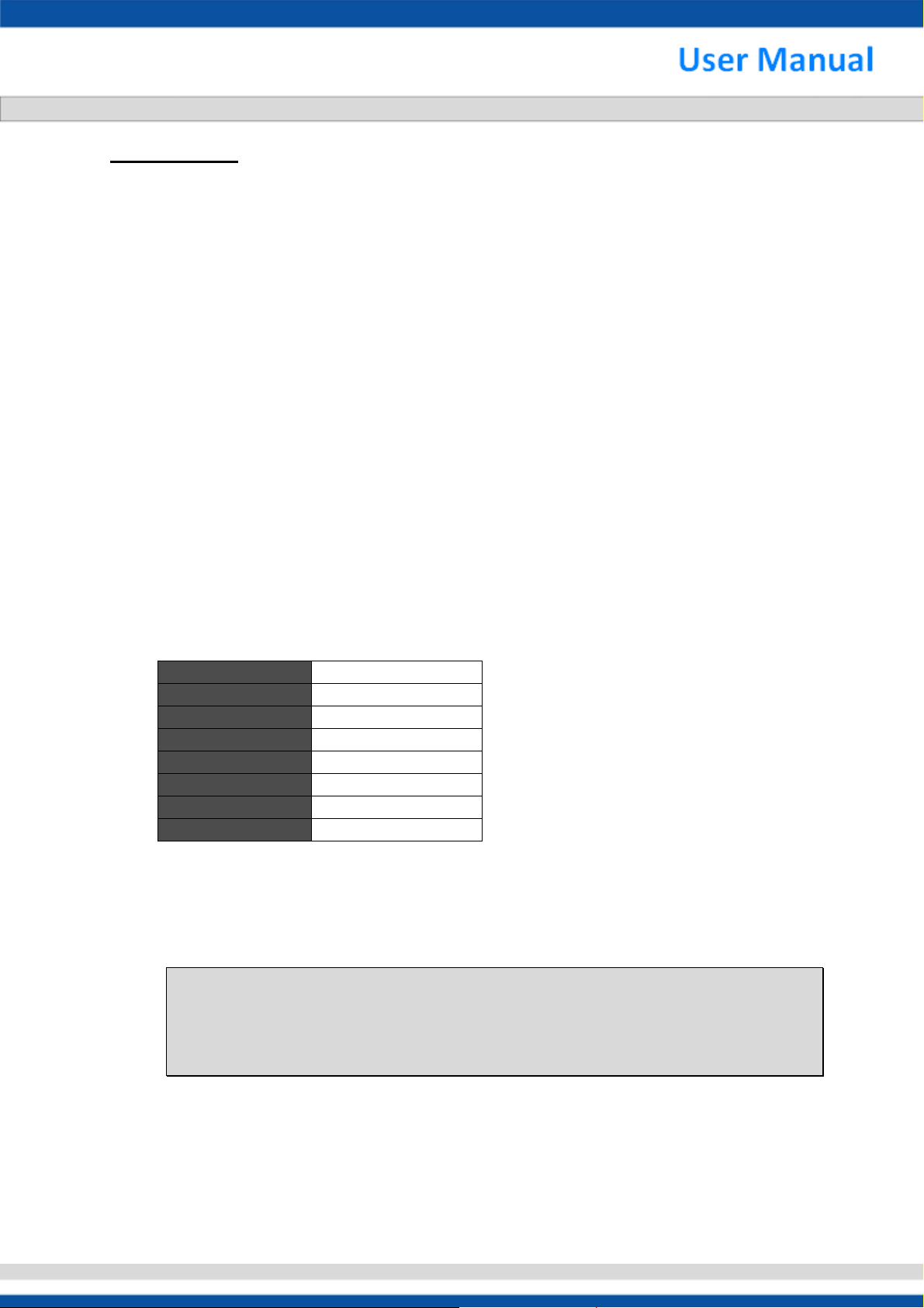
1.3 System Requirements
For IE Browser Live View--
Resolution 1280x720p
Suggested Bitrate 2000~4000kbps
Compression format H264 or MPEG4
Frame Rate Up to 30fps
CPU (Recommended) Intel Core i3 or above
RAM 2GB RAM
IE Browser 8.0 or above
OS WinXP or above
Microsoft Internet Explorer 8.0 or above (Only support 32bit IE Browser)
The compression format of IP Cam encoder is in H.264/High profile.
When using Live view in IE Browser, IP Cam will decode in real time by RTSP, the maximum
bitrate is 10,000kbps.
NOTE:
It is strongly suggested that the user browse with Internet Explorer. Browsers other than
Internet Explorer are NOT fully supported when the manual published, hence, the
manufacturer WILL NOT BE LIABLE FOR ANY LOSS OR DAMAGE CAUSED.
1
130918-2112TU-F-V2.6-V1

1.4 Specification
TV System PAL N TSC
Video Compression H.264. MPEG4, M-JPG
Video Frame Rate 25 fps@960x576 30 fps@960 x480
Max. Resolution 960H
Browser IE 8.0 or Above
Ethernet 10/100M Auto Negotiation
Bit Rate Transmission 64~12,000 Kbps
Supported Protocols TCP, UDP, HTTP, SMTP, FTP, NTP, DNS, DHCP, PPPoE, ARP,
UPnP, RTSP, RTP, SNMP, TRAP, Ethernet (RJ-45 Wired
10/100 Base-TX)
Video Streaming H.264, MPEG4 and M-JPEG Dual/Triple Streaming
Audio Streaming Two-way Audio ; G.711 (μLaw), 8KHz/16KHz Sample Rate
Users Support 9 Users
Security ID/Password Protection
General Function DI/DO Event Triggered via Ethernet ; Built-in Web Server &
Network Interface
Alarm Trigger File Upload via FTP and Email/Notification via Email, HTTP,
External Digital Output Activation, micro SD Recording
Multicast Support Multicast Function
Serial Port Terminal Blocks (RS-485)
Analog Video Input / Output Compositex1, F/BNC Connector
Audio Input / Output 1.4 Vp-p, 1Vrms, 3.5 mm Jack
DI/DO DIx1 ; DOx1
Power Supply 12Vdc/PoE
Consumption 4.0W
Operation Temperature -10°C~50°C
Storage Temperature Max. RH80%
Storage Humidity -20°C~60°C
Dimensions 124(W)x43(H)x100(D)mm
Weight 350g
Subject to change without notice.
2
130918-2112TU-F-V2.6-V1

1.5 Dimensions
(Unit: mm)
3
130918-2112TU-F-V2.6-V1

1.6 Camera Overview
■ Power / LAN LED:
■ DI / DO Port:
■ RESET:
■ DC 12V:
■ Audio In/Out:
■ Video In/Out:
■ WAN/PoE:
Audio In/Out
Video In/Out
Power / LAN
Power / LAN LED
(1) Power LED: Green—Normal Orange—Abnormal
(2) LAN LED: Green—Successfully Connected Red—Connecting Orange—Error
(1) 485+: Controlled by RS-485 signal sent by the network part. (POSTIVE)
(2) 485-: Controlled by RS-485 signal sent by the network part (NEGATIVE).
(3) GND: Ground
(4) AL-O2 (Alarm Output): No effect
(5) AL-I2 (Alarm Input): No effect
(6) AL-O1 (Alarm Output): Triggered when the alarm outputted (TTL Level).
(The alarm output signal may also be set to generate as the DAY/NIGHT Mode activated.)
(7) AL-I1 (Alarm Input): When activate, the alarm will be triggered.
(The input may also set to be controlled by DAY/NIGHT program.)
(8) ALM-RST (Alarm Reset): The system will force the alarm input to cancel.
Press reset key with small screw driver, hold for a few seconds, and re-connect the power, the
camera will automatically start to reset in 5 seconds. After reset, all the settings will restored to
the default. The default IP is 192.168.1.168. After reset, IP will be restored to the default.
DC Jackψ2.1, DC12V---0.5A or higher.
Audio In: Connect with MIC (Microphone).
Audio Out: Connect with Speaker.
Video In: Connect with Analog D1(960H) Camera.
Video Out: Connect with Monitor(BNC).
Connect Analog D1(960H) Camera to PC or PoE Hub.
IN
OUT
1 2 3 4 5 6 7 8
1.485+
2.485 -
3.GND
4.AL-O2
5.AL-I2 6.AL-O1
7.AL-I1
8.AL-RST
Mini
USB
WAN / PoE
Power 12V DC
Micro SD /
SDHC
Mini USB
DI / DO
4
130918-2112TU-F-V2.6-V1

1.7 Installation
1. Installation Flow Chart
Default Settings of IP CAM
IP Address: 192.168.1.168
User Name: admin
Password: 9999
Suggested IP Address For PC/NB
IP Address: 192.168.1.200
Subnet Mask: 255.255.255.0
Gateway: 192.168.1.1
PoE
Check the power of PoE
Connect the RJ-45 LAN cable to the IP CAM
Turn on the PC/NB and log-in Windows OS
(Please see the suggested IP address)
Disable the anti-virus software and firewall
Run IE browser (IE 8.0 or above)
Type the URL http://192.168.1.168
and get into IP CAM setting window
User Name: admin Password: 9999
Get into the IP CAM setting window
START
Power Type
Plug the Power Adapter
IP setting for PC/NB
FINISH
DC
NOTE:
Use PoE device for power supply is only available to cameras with PoE function. Cameras without PoE
function need to be connected directly to the power supply.
5
130918-2112TU-F-V2.6-V1

2. Direct Link
Make sure PC installed with JAVA Version 6 Update 30 or above
(1) Plug the power adapter to IP CAM.
(2) Run the IE browser with http://192.168.1.168
(3) When the log-in window pop-up, please input the User Name and Password.
(4) Whenever the connection is ready, the main page (setting window) of IP CAM will show
on.
Adapter
Cat-5 LAN cable
3. Link via Hub / PoE Hub
(“Link via PoE Hub” applied only to models with PoE function)
Make sure PC installed with JAVA Version 6 Update 30 or above
(1) Run the IE browser with http://192.168.1.168
(2) When the log-in window pop-up, please input the User Name and Password.
(3) Whenever the connection is ready, the main page (setting window) of IP CAM will show
on.
Cat-5 LAN cable
Hub / PoE
Cat-5 LAN cable
6
130918-2112TU-F-V2.6-V1

2. USER INTERFACE
2.1 Login
1. Start the browser, and input
NOTE:
It is strongly suggested that the user browse with Internet Explorer. Browsers other than
Internet Explorer are NOT fully supported when the manual published, hence, the
manufacturer WILL NOT BE LIABLE FOR ANY LOSS OR DAMAGE CAUSED.
http://192.168.1.168/ in the address field, then press Enter.
2. Enter User Name and Password In the prompt window, and click OK.
The default User Name and Password is admin and 9999. You will need to enter the account and password
every time whenever you restart the application or reconnect.
7
130918-2112TU-F-V2.6-V1

2.2 Interface Overview
After login to the system, the screen will be displayed as below:
On the left side are the buttons of the function pages. The functions each page performs are listed
in the table below. More information will be given in the following sections. Whenever the
adjustment completed, click Submit to save the settings.
Note:
The content of the function pages may vary by model.
Live View
Video
Image
Audio
DateTime
Network
Alarm
Storage
Maintain
PTZ/OSD
8
130918-2112TU-F-V2.6-V1

1. Live View
Main page. Display the image captured by the camera.
Language:
English / 日本语 / 繁中 / 简体中文 / Россия / Magyar / Deutsch /
اناﺮﻳ / España / Polska / Nederlands / Portuguese / Francais
(Language options may vary by region)
Full Screen
Snapshot
Record & Save
Stop Recording
Audio On
Audio Off
Zoom in
Zoom out
Restore
Information
Motion Detect
PTZ Control (Applied only to models with PTZ function):
Stop (center button) / 8-direction Keys (outer buttons)
Zoom Out Zoom In
Wide Te l e
9
130918-2112TU-F-V2.6-V1

2. Video
Modify the settings of IP video settings, stream type and local display.
Stream Type
Video Streams Single / Dual / Tri-stream
Codec Profiles H.264 / MPEG4 / MegaPixel JPEG
Resolution H.264: D1, H.264: 960H
Stream1 H.264
Frame rate 1 / 3 / 5 / 10 / 12 / 15 / 20 / 25 fps
Bitrate Fill in the bitrate value
Rate Control OFF / VBR / CBR
(NOTE: The content may vary by model)
10
130918-2112TU-F-V2.6-V1

3. Image
Modify the settings of image, OSD and advanced image settings.
Stream1 / Stream2 / Stream3 OSD
Mode Date / Time / Text
Text Position Top-Left / Top-Right
Local Display
Date Position Bottom-Right / Bottom-Left
Time Position Bottom-Right / Bottom-Left
Local Display OFF / NTSC / PAL / HD720P
Rotation OFF / HORIZONTAL / VERTICAL / BOTH
Size 5 sec / 10 sec
Format H.264 (960 x 480)
(NOTE: The content may vary by model)
11
130918-2112TU-F-V2.6-V1

4. Audio
Modify the settings of audio.
Audio
Enable Audio Enable / Disable
Audio Mode MIC / SPEAKER / BOTH
Input volume 0~100
Sample Rate/Bitrate 8Khz/64Kbps / 16Khz/128Kbps
Output Volume 0~100
(NOTE: The content may vary by model)
12
130918-2112TU-F-V2.6-V1

5. DateTime
Modify the settings of date and time.
DateTime
TimeZone Select the time zone
Day light Enable / Disable
Set Manual Date / Time Manual set the date and time
Sync Current PC Date / Time Synchronization the date and time with current PC
Sync with SNTP Server Synchronization the date and time with SNTP Server
Date Format Select the format of date
Time Format Select the format of time
13
130918-2112TU-F-V2.6-V1

6. Network
Modify the settings of network and IP address.
DHCP / Static IP / PPPoE
Use DHCP Select to use DHCP for connection
Static IP Select to use static IP for connection
IP Address Domain name of IP address
Mask Domain name of mask
Gateway Domain name of gateway
DNS Domain name of DNS
PPPoE Select to use PPPoE for connection
Account Enter account
Password Enter password
Multicast
Enable Multicast Enable / Disable
H264 Main / Sub Port Communication port for H.264
MPEG4 Main / Sub Port Communication port for MPEG4
MJPEG Port Communication port for M-JPEG
14
130918-2112TU-F-V2.6-V1

SMTP
SMTP Auth Enable / Disable SMTP authentication
Account Enter account
Password Enter password
Sender Assign mail address of Sender
Server Domain name of SMTP server
Mail list List of mail account
FTP Server
FTP Server Domain name of FTP server
Port 21
Account Enter account
Password Enter password
Upload Path Assign upload path
DDNS
DDNS Enable / Disable
Domain Domain name of DDNS server
Account Enter account
Password Enter password
Service DDNS service provider
Http / Onvif
Http Port Domain name of HTTP port
OnvifPort 8080 (Using Onvif must sync PC time)
SNTP Server
SNTP Server Domain name of SNTP server
SNMP Server
SNMP Server Domain name of SNTP server
15
130918-2112TU-F-V2.6-V1

7. Alarm
Modify the settings of alarm trigger and actions.
Alarm
Enable Alarm Enable / Disable
Alarm Duration The duration of alarm
Alarm Trigger
Motion Motion trigger alarm (None support for single M-JPEG)
Ethernet Lost Trigger alarm on Ethernet loss
DI1 Mode Trigger mode for DI
DI1 Level Alarm level of DI
Alarm Action
Upload via FTP Upload via FTP on receiving alarm signal
Upload via SMTP Upload via SMTP on receiving alarm signal
Local Storage Save Save to local storage on receiving alarm signal
Play Sound
DO1 Mode Trigger mode for DO
Play sound on receiving alarm signal
(Need to enable Speaker in Audio Mode)
DO1 Level Alarm level of DO
16
130918-2112TU-F-V2.6-V1

8. Storage
Modify the settings of storage and files upload.
Storage
Upload via FTP File format for upload via FTP
Local Storage Save File format for save files
Schedule Set the storage schedule time of a week
17
130918-2112TU-F-V2.6-V1

9. Maintain
Maintain the user name, password and update the firmware.
Maintain
Current Version Current version of the firmware
Mac Address Mac address assigned by production
Firmware Update
IP CAM Restart Reboot this IP camera after firmware updated
Snapshot Record Folder
Name / Password Change the login User Name and Password
Authority Change the authority level of users
User List User list of this IP camera
Add / Del User Add / Delete the user
Log List Login list of this IP camera
SD format Format the SD in use
Browse and select the firmware downloaded from official site,
and click Update to update the firmware
Click select to select a folder to save snapshots and
real-time recording data
18
130918-2112TU-F-V2.6-V1

10. PTZ/OSD
Define the commands of PTZ (Pan/Tile/Zoom)/OSD. The default protocol is Pelco D and Pelco
P. Use protocols other than Pelco D and Pelco P, define the commands in the field of
Customize.
General
Full Screen PTZ Enable / Disable Full Screen PTZ
ID 0~255
Baud 1200 / 2400 / 4800 / 9600 / 19200 / 38400 / 57600 / 115200
Pelco D / Pelco P
Zoom
Pan
Tilt
0~3
0~63
0~63
Customer
Stop
Up / Down
Left / Right
Zoom in / Zoom out
Wide / Tele
SET: Create and define commands
19
130918-2112TU-F-V2.6-V1
 Loading...