

Page 1
HORNOS DE GAS
MODELOS:
102HGB
112HGN
122HGI
202HGB
212HGN
222HGI
HG61IB
HG61IN
MANUAL DE INSTRUCCIONES DE USO,
INSTALACIÓN Y MANTENIMIENTO.
1 VITROKITCHEN 12-2007 CE HORNO GAS.doc
Page 2

ÍNDICE
IMPORTANTES INSTRUCCIONES DE SEGURIDAD 3
INSTRUCCIONES PARA EL USO DEL HORNO:
PILOTO INDICADOR 4
MINUTERO MANUAL 4
RELOJ ELECTRÓNICO 4
CONMUTADOR DE FUNCIONES 6
UTILIZACIÓN DEL GRILL ELECTRICO 7
UTILIZACIÓN DEL GRILL A GAS 7
UTILIZACIÓN DEL QUEMADOR A GAS 8
MANTENIMIENTO Y LIMPIEZA DEL HORNO 8
ELIMINACIÓN DE DEFECTOS 9
PUERTA DEL HORNO 9
SUSTITUCIÓN LÁMPARA DEL HORNO 10
INSTRUCCIONES PARA LA INSTALACIÓN:
ENCASTRE DEL HORNO EN EL MUEBLE 11
CARACTERÍSTICAS DEL MUEBLE 11
VENTILACIÓN 12
CONEXIÓN ELÉCTRICA 13
CONEXIÓN A LA RED DE GAS 14
CONVERSIÓN GAS 15
REGULACIÓN DE LA LLAMA DEL MÍNIMO 16
ASISTENCIA TECNICA Y RECAMBIOS 16
DATOS TÉCNICOS DE LOS QUEMADORES GAS 17
DIMENSIONES EXTERNAS 17
DATOS TÉCNICOS DEL HORNO 17
GRAFICOS SOBRE USO Y MANTENIMIENTO 19 – 23
página
4
11
2 VITROKITCHEN 12-2007 CE HORNO GAS.doc
Page 3

IMPORTANTE: CONSERVAR ESTE MANUAL.
IMPORTANTES INSTRUCCIONES PARA LA SEGURIDAD
Leer las siguintes instruciones antes de instalar y usar el horno,
para prevenir potenciales riesgos de incendio, shock eléctrico, daños a las
personas o daños al mismo horno por causa de un uso incorrecto.
El horno está construido según las Directivas Europeas 90/396/CEE (gas),
73/23/CEE (baja tensión) y 2004/108/CEE (compactibilidad
electromagnetica). Este producto presenta los requisitos requeridos por las
Normas Europeas vigentes.
La Instalación, Mantenimento y Asistencia tienen que ser efectuados
por personal especializado y autorizado.
NOTA: NO LEVANTAR NUNCA Y/O COGER EL HORNO
AGARRANDOLO POR EL TIRADOR DE LA PUERTA.
ATENCIÓN:
1) No almacenar objetos inflamables y no resistentes al calor dentro del
horno o a su alrededor.
2) No usar nunca el horno para calentar la habitación.
3) No obstruir el paso de evacuación de los gases de combustión y del aire
fresco, bloqueando los orificios de ventilación del local y del horno. Esto crea
un funcionamiento anormal con aumento del monoxido de carbonio a un nivel
peligroso.
4) El uso de un horno a gas produce calor y humedad en el local donde está
instalado. Garantizar una buena aireación del local. Tener abiertas las
aberturas de ventilación natural e instalar una campana de extracción.
5) El uso continuado del horno podria requerir una ventilación extra, esto
podría resolverse abriendo una ventana o aumentando la potencia de la
campana de aspiración con relativo aumento del aire reciclado.
6) En caso que la llama se apague, cierre inmediatamente el grifo del
quemador. Ante un fuerte olor a gas, abrir una ventana y esperar unos 5
minutos antes de encender de nuevo.
7) Controlar que todos los mandos estén en posición de Apagado “0” antes
de proceder con la conexión del horno a la red de gas.
8) Antes de la instalación, verificar las condiciones y características técnicas
de la distribución local del gas con las características técnicas del horno, las
cuales tinen que ser compatibles.
3 VITROKITCHEN 12-2007 CE HORNO GAS.doc
Page 4

9) Las características de regulación de este horno están indicadas en la
etiqueta del producto y en este manual.
10) Este horno no está conectado a un aparato de evacuasión de los gases
de combustión. Tiene que ser instalado conforme a las normas de
instalación en vigor de cada país. Hay que prestar una particular atención a
las disposiciones aplicables en materia de ventilación.
11) Durante su uso el horno se calienta, por lo tanto, tener cuidado de no
tocar los elementos calientes dentro del horno.
12) Las partes accecibles pueden calentarse mucho durante el
funcionamiento del horno. Conviene tener los niños a distancia de
seguridad.
13) No sobrecargue la puerta abierta y no se apoye sobre ella. Tampoco
dejar caer la puerta al abrirla.
ATENCIÓN:
No obstruir los medios de evacuasión de los gases de combustión y de
entrada del aire fresco del local. La reducción del paso de flujo puede causar
un incremento del porcentaje de Monoxido de Carbonio a un nivel peligroso.
En el caso de que la llama se apague durante el funcinamiento, apagar el
quemador girando a “0” los mandos de control. Luego, en caso de olor a gas
en el local, abrir una ventana hacia el exterior y esperar unos 5 minutos antes
de encender nuevamente el quemador del horno.
Asegurarse de que todos los mandos de control estén en poisición de
cerrado antes de conectar el horno a la instalación de la red de gas.
INSTRUCIONES PARA EL USO DEL HORNO
PILOTO INDICADOR ROJO EN EL PANEL DE MANDOS.
Cuando la luz roja está encendida, significa que el horno está en
funcionamiento y conectado electricamente.
MINUTERO
Reloj mecanico con un maximo de 90 minutos. Al finalizar el plazo de tiempo
seleccionado, se escuchará una señal acústica. Este roloj mecánico no tiene
ningún control activo sobre el funcionamiento del horno. Fig. 08
RELOJ ELECTRÓNICO
Después de haber conectado el horno a la red eléctrica y en caso de fallo de
la corriente eléctrica, la pantalla del reloj comenzerá a lucir intermitente. Fig.
09.
4 VITROKITCHEN 12-2007 CE HORNO GAS.doc
Page 5

REGULACIÓN DE LA HORA DEL DIA
Seleccionar el botón . Regular la hora del dia actuando con el “+” y “-” .
Esta función queda activada durante 7 segundos después de la ultima
activación del botón “+” o “-” .
MODIFICAR LA HORA DEL DIA
Seleccionar y oprimir el botón durante 4 segundos hasta que la
pantalla comienze parpadear. Modificar la hora del dia actuando sólo con los
pulsadores “+” o “-” . Los minutos y segundos escondidos no serán
modificados.
REGULAR EL FUNCIONAMIENTO DEL MINUTERO ELECTRÓNICO
Esta función se activa con el botón “+”. Luego, oprimir nuevamente el botón
de “+” para incrementar el tiempo de funcionamiento.
La unidad de regulación es de 10 segundos. El contador de cuenta atrás
tiene la prioridad sobre la pantalla.
El maximo tiempo regulable es de 10 horas. Durante la regulación, después
de haber superado los 99 minutos y 50 segundos, la regualción de la hora
cambia en 1h y 4 minutos.
Para ver de nuevo la hora del dia durante el contador de cuenta atrás, oprimir
el botón . La hora del dia aparecerá durante sólo 6 segundos, luego el
contador de cuenta atrás aparecerá de neuvo.
PARA REGULAR NUEVAMENTE EL RELOJ ELECTRÓNICO
Oprimir el botón “-” constantemente hasta que en la patalla aparezca el Cero.
SEÑAL ACÚSTICA
Una vez obtenida la hora de la Alarma regulada, la señal acústica sonará
durante 7 minutos. Para interrumpir la señal acústica, oprimir el botón .
La señal acústica puede ser anulada antes de que llegue la hora de la alarma
seleccionando el botón 15 segundos antes de la hora de la alarma.
REGULACIÓN DE LA SEÑAL ACÚSTICA
Es posible regular la frecuencia y intensidad de la señal acústica oprimiendo
el botón “-“ .
5 VITROKITCHEN 12-2007 CE HORNO GAS.doc
Page 6
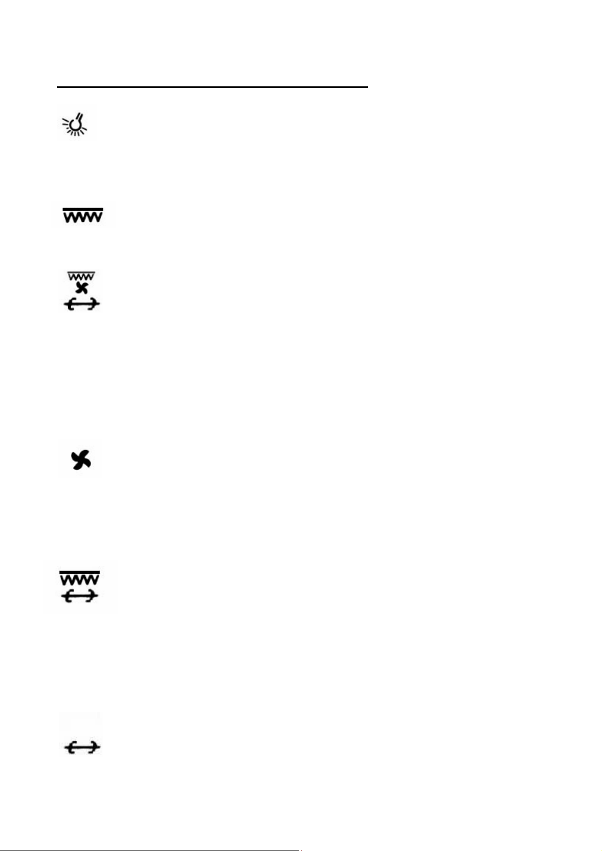
CONMUTADOR O SELECTOR DE FUNCIONES
El conmutador activa la función deseada para la cocción.
LÁMPARA HORNO (GE; GEVT; GGVT)
Utilizar esta función para encender la lámpara del horno.
El funcionamiento de la lámpara combina también con otras
funciones.
GRILL (GE; GEVT)
Utilizar esta función para el grill eléctrico. Leer párrafo “Utilización
del Grill Electrico” para más información.
GRILL VENTILADO (GEVT)
Usar esta función para asar a la parilla con la ayuda del Rustepollos y aire caliente. Para uitilizar la función se recomienda
precalentar el horno usando el grill. Introdicir el ruste-pollos, con
el alimento ya trinchado en el espadín y colocarlo en el interior de
la cámara apoyándolo en los soportes correspondientes. Colocar
debajo del espadín del ruste-pollos la bandeja recoge salsas.
Atención: quitar el mango del espadín antes de comenzar la
cocción. Para información adicional, leer el capítulo, Utilización
del Grill Eléctrico.
DESCONGELAR Y SECAR (GEVT; GGVT)
Usar esta función para acelerar el proceso de descongelación y/o
secar la comida, con la utilización del aire forzado.
Usar esta función junto al quemador horno para obtener una
cocción más uniforme. El ventilador no funciona junto al Grill
Gas. Solo funciona con el Grill Eléctrico o sólo con Ventilador.
GRILL ELÉCTRICO CON RUSTE-POLLOS (GE; GEVT)
Usar esta función para asar a la parrilla con la ayuda del Ruste-
pollos. Para utilizar esta función se recomienda precalentar el
horno usando el grill, Introducir el ruste-pollos, con el alimento ya
trinchado en el espadín y colocarlo en el interior de la cámara
apoyándolo en los soportes correspondientes. Colocar debajo del
espadín del ruste-pollos la bandeja recoge salsas. Atención:
quitar el mango del espadín antes de comenzar la cocción. Para
información adicianal, leer el capítulo, Utilización del Grill
Eléctrico.
SELECCIÓN DEL RUSTE-POLLOS (GE; GGVT)
Esta función enciende el motor Ruste-pollos.
6 VITROKITCHEN 12-2007 CE HORNO GAS.doc
Page 7

VENTILADOR HORNO Y RUSTE-POLLOS. (GGVT)
Esta función permite el uso del Ventilador Horno junto al
Ruste-pollos. Esta función no puede ser seleccionada durante la
utilización del quemador Grill Gas.
UTILIZACIÓN DEL GRILL
SELECCIÓN GRILL ELÉCTRICO
Seleccionar la función Grill en el conmutador o selector y posicionar el
termostato a la temperatura máxima para permitir un periodo de
precalentamiento de la cámara de cocción antes de introducir los alimentos.
Introducir la comida en el horno en la posición más cerca al Grill. Siempre
dejar la puerta del horno abierta durante el utilización del Grill. También,
utilizar el Grill por un tiempo máximo de 15 minutos.
NB: Un dispositivo de seguridad no permite el funcionamiento del Grill si el
mando del horno gas no está en posición de apagado “ ”.
QUEMADOR GRILL A GAS
Gracias a un dispositivo de seguridad, para encender el quemador del horno
y el grill gas, la puerta del horno tiene que estar completamente abierta.
Girar el mando del grifo-termostato del horno en sentido horario y
posicionarlo en la posición de Grill. Luego, apretar a fondo el mando, Fig. 7B.
Después de haber encendido el quemador, seguir apretando el mando
durante unos 10 segundos, luego soltar el mando. Si la llama se apaga, hay
que repetir la operación de encendido apretando nuevamente el mando.
Una vez encendido el horno, introducir el alimento para la cocción.
Como en el caso de Utilización del Grill Eléctrico, permitir un periodo de
precalentamiento de la cámara de cocción antes de introducir los alimentos.
Introducir el alimento en el horno en la posición más cerca al Grill. Siempre
dejar la puerta del horno abierta durante la utilización del Grill Gas. También,
utilizar el Grill Gas por un tiempo máximo de 15 minutos.
ATENCIÓN: Durante el uso del Grill el horno se calienta. Tener cuidado
de no tocar elementos calientes dentro del horno. Por lo tanto conviene
mantener a los niños a una debida distancia de seguridad.
7 VITROKITCHEN 12-2007 CE HORNO GAS.doc
Page 8

UTILIZACIÓN DEL QUEMADOR DEL HORNO
ATENCIÓN: Gracias a un dispositivo de seguridad, para encender el
quemador horno y grill gas la puerta del horno tiene que estar
completamente abierta.
Girar el mando en sentido antihorario y posicionarlo en la posición de
máximo de 260°C, Fig. 7A. Luego, apretar el mando hasta que se encienda
el quemador. Verificar presencia de la llama observando atraves del orificio
“F”.
Después de haber encendido el quemador, seguir apretando el mando
durante unos 10 segundos, luego soltar el mando. Si la llama se apaga, hay
que repetir la operación de encendido apretando nuevamente el mando. En
el caso de que el quemador quede encendido, girar el mando del grifotermostato y posicionarlo en la temperatura de cocción deseada.
El horno tiene un dispositivo de seguridad que bloquea la salida de gas en
caso de que la llama se apague accidentalmente.
Para apagar el quemador desde la posición de minimo o de qualquier
posición, es suficiente apretar y girar el mando hasta la posición “ ”.
Se recomienda precalentar el horno hantes de la cocción del la comida.
LIMPIEZA Y MANTENIMIENTO
SEGURIDAD EN LA LIMPIEZA
ATENCIÓN: No usar limpiadores a vapor para la limpieza del horno o de
ninguna parte de el. No usar materiales con superficies rugosas, abrasivas o
espátulas metálicas para limpiar cualquiera superficie del horno, porque
pueden rayarla y dañarla causando también así la fractura del vidrio o del
esmalte de la superficie.
Apagar los quemadores y resistencias electricas, y luego esperar que todos
los elementos se enfríen antes de tocarlos o limpiarlos. Limpiar el horno con
cuidado. Atención a evitar quemaduras de vapor en caso que se use una
esponja húmeda para la limpieza de residuos al entrar en contacto con
superficies calientes. Tampoco usar detergentes que puedan crear humos
toxicos cuando estén a contacto con superficies calientes o expuestos a altas
temperaturas.
8 VITROKITCHEN 12-2007 CE HORNO GAS.doc
Page 9

LIMPIEZA DE LA SUPERFICIE
Usar una esponja o paño húmedo con detergente no abrasivo sobre la
superficie en la zona sucia. Luego, limpiar y secar utilizando una esponga o
paño seco. En caso de residuos fuertes o difíciles de quitar, al igual que las
partes de acero inoxidables con suciedad incrustada, utilizar solo una
esponja de plastico, espátula de plastico o similar y limpiar con agua tibia y
vinagre.
A causa di una creciente presencia de nuevos productos para la limpieza
cada año en el mercato, no es posible indicar una lista de productos adaptos
a la limpieza de este horno. Lea cuidadosamente las instrucciones del
fabricante del detergente para verificar si tal detergente puede ser usado o
no.
ELIMINACIÓN DE DEFECTOS
EL HORNO DEBE ESTAR SIEMPRE DESCONECTADO DE LA
CORRIENTE ELÉCTRICA ANTES DE PROCEDER A CUALQUIER TIPO DE
MANIPULACIÓN POR MANTENIMIENTO O REPARACIÓN.
Los siguientes defectos son considerados como problemas que afectan al
normal funcionamiento del horno, y como tal hay que contactar con el centro
de Asistencia Técnica más cercano para resolver el problema:
- Llama con puntas amarillas.
- Dificultad a encender el quemador.
- El quemador no queda encendido.
- El quemador se apaga.
- Dificultad al girar el grifo termostato del horno a gas.
NOTA:
Controlar regularmente el correcto funcionamiento de los grifos, termostatos
y selectores.
PUERTA HORNO
DESMONTAJE DE LA PUERTA DEL HORNO, Fig. 11A e 11B.
1) Abrir completamente la Puerta del Horno.
2) Inmovilizar la bisagra en ambos lados de la puerta poniendo la
abrazadera “U” en el retén del arco de la bisagra, ver figura 06. Esta
operación sirve para inmovilizar la bisagra en ambos lados de la puerta y
9 VITROKITCHEN 12-2007 CE HORNO GAS.doc
Page 10

evitar el cierre accidental de la misma durante la operación de desmontaje
de la puerta.
3) Sujetar la puerta con ambas manos, girarla unos 45° en sentido de cierre
y luego sacarla de los asientos de las bisagras.
4) Levantar la puerta tirando algunos centímetros para sacarla de los
asientos de las bisagras.
5) Cuando la puerta esté suficientemente elevada, será posible sacar la
puerta del horno
ATENCIÓN: El arco de la bisagra está tenso y por eso hay que sacar la
puerta con precaución para no dañarse los dedos.
MONTAJE DE LA PUERTA DEL HORNO, Fig. 11A e 11B.
1) Sujetar la puerta con ambas manos, posicionarla en los asientos de las
bisagras.
2) Girar la puerta hacia abajo en sentido de abierto total y sacar la
abrazadera “U” del retén del arco de la bisagra. De esta manera la
bisagra queda libre para girar y cerrar.
3) Cerrar la puerta del horno para verificar que las bisagras estén libres y
que la puerta se cierre correctamente.
ATENCIÓN: No sacar nunca la abrazadera “U” del retén cuando la puerta
esté no esté montada. No usar el horno hasta que la puerta no esté
correctamente en posición.
Abrir y cerrar la puerta del horno sosteniéndola con la mano. No dejarla caer
cuando se esté abriendo o cerrando. No apoyar los alimentos sobre la puerta
abierta. Todos estos factores y otros para los cuales la puerta no está
diseñada podrían dañar las bisagras, romper la puerta, o producir daños
personales.
DESMONTAJE DE LA LÁMPARA DEL HORNO
ATENCIÓN: Para prevenir descargas eléctricas o daños personales, seguir
el siguiente procedimiento:
Antes de sustituir la lámpara del horno, asegurarse que la corriente eléctrica
esté desconectada desde el interruptor general y de la red de alimentación
eléctrica.
1) Asegurarse de que el horno y la lámpara estén fríos.
2) Quitar la tapa que cubre la lámpara “A” desenroscándola.
3) No tocar la lámpara caliente con un paño húmedo, puede causar la rotura
de la lámpara.
4) Desenroscar y sustituir la lámpara con una nueva para electrodomésticos
cuyos parametros son: tipo E14; 230Vac – 25 W, o el voltage tiene que
10 VITROKITCHEN 12-2007 CE HORNO GAS.doc
Page 11

corresponder con los parametros del horno y con resistencia a la
temperatura de 300°C,
5) En el caso que la tapa de la lámpara esté dañada o rota, no usar el horno
haste que la tapa de la lámpara sea sustituida con una nueva y fijada de
modo correcto y seguro.
6) Enroscar nuevamente la tapa de la lámpara y conectar el horno a la red
eléctrica.
INSTRUCCIONES PARA LA INSTALACIÓN
NO ALZAR O COGER EL HORNO POR EL TIRADOR.
ATENCIÓN: PARA UNA CORRECTA INSTALACIÓN Y USO, SE DEBE
TENER EN CUENTA LOS DATOS TÉCNICOS DEL PRODUCTO. POR
FAVOR, COMPROBAR LA ETIQUETA DEL HORNO PARA VERIFICAR
LOS DATOS DEL PRODUCTO CON LOS DE LA RED DE GAS Y DE
CORRIENTE ELÉCTRICA.
ENCASTRE DEL HORNO EN EL MUEBLE:
El horno pude ser instalado en una columna o bajo la encimera ya sea de
madera o de cocción.
Las dimensiones del hueco que debe tener el mueble para el encastre del
horno, están indicadas en la fig. 01. Asegurarse de que el mueble en el cual
será instalado el horno resista una temperatura maxima de 100°C y que la
base que soporta el horno pueda soportar un peso de 45 kg para el
mod. FI 90, FI 70 y 30 kg para FI 60.
Las dimensiones del hueco del horno para el encastre están indicadas en la
Fig. 01A para FI 60, Fig. 01B para FI 70, y Fig. 01C para FI 90.
En el fondo del mueble o en la base del soporte del horno se debe hacer
una abertura, en la zona posterior de al menos 80 mm, ver fig. 01, para
permitir la circulación de aire para la correcta combustión y enfriar el
exterior del horno durante su funcionamiento.
Asegurarse que el horno esté instalado de manera segura en el mueble.
Usar los tornillos “A”, figura 02, para la fijación del horno.
CARACTERÍSTICAS DEL MUEBLE: Los requisitos técnicos del mueble
son los siguientes;
- El mueble y sus componentes deben de soportar una temperatura máxima
de 100 °C sin presentar alguna deformación y/o defectos en su superficie.
11 VITROKITCHEN 12-2007 CE HORNO GAS.doc
Page 12

- El mueble debe permitir el paso libre del cable de conexión eléctrica y del
tubo del gas.
12 VITROKITCHEN 12-2007 CE HORNO GAS.doc
Page 13

Todos los muebles para la cocina de uso doméstico deben estar protegidos
con material autoestinguente tal como requieren las Normas Europeas o
Normativas Locales vigentes.
NOTA:
LA INSTALACIÓN Y ASISTENCIA TÉCNICA DEBEN DE SER
REALIZADAS SÓLO POR PERSONAL ESPECIALIZADO.
LEER LAS INSTRUCCIONES PARA LA SEGURIDAD EN ESTE MANUAL
ANTES DE UTILIZAR EL PRODUCTO.
UNA INCORRECTA INSTALACIÓN, REGULACIÓN, MANTENIMIENTO,
ASISTENCIA, O UTILIZACIÓN, PUEDE CAUSAR SERIOS DAÑOS A LAS
PERSONAS O A LAS COSAS.
Este producto tiene que ser instalado como se indica en este Manual de
Instalación y en conformidad con las normas nacionales y reglamententos
locales vigentes.
VENTILACIÓN
La Ubicación del horno tiene que presentar una buena ventilación según los
requisitos del D.M. del 21/041993 o Norma Europea EN 30.1.1 La ventilación
tiene que garantizar el correcto intercambio de los gases de la combustion,
circulación del aire y mantener la temperatura de trabajo en los límites de
seguridad.
ETIQUETA DEL PRODUCTO
La etiqueta de características del horno está situada sobre el borde lateral
izquierdo de la cámara de cocción. Una segunda etiqueta se encuentra junto
al manual de instrucciones. Esta etiqueta lleva los datos de identificación y
técnicos del horno y también las referencias para los pedidos de piezas de
repuestos.
13 VITROKITCHEN 12-2007 CE HORNO GAS.doc
Page 14

CONEXIÓN ELÉCTRICA DEL HORNO
SEGURIDAD ELÉCTRICA
IMPORTANTE: EL horno debe ser instalado por un instalador especializado
o autorizado y la instalación debe hacerse según las normas vigentes de
seguridad.
CONEXIÓN ELÉCTRICA
ATENCIÓN: Quitar la corriente eléctrica antes de la instalación del horno.
La conexión eléctrica de este horno debe de ser del tipo monofásica 230 V~
– 50 Hz, con cable flexible. Verificar en la etiqueta del producto, voltaje
correcto y frecuencia de potencia eléctrica con la red de energia eléctrica.
En caso de una conexión directamente a la red eléctrica, se debe intercalar
un interruptor bipolar con la capacidad correspondiente a la potencia del
horno con una separación de contactos de al menos 3 mm, según requiere la
normativa vigente. El cable de Tierra amarillo-verde no debe ser interrumpido
en ningún caso por el interruptor. La toma o el interruptor bipolar debén de
ser de facil acceso una vez instalado el horno.
Todos los modelos de hornos son fabricados con el cable eléctrico con o sin
el enchufle. En caso de necesidad de instalación del enchufe, éste debe
corresponder con la potencia máxima del horno, verificar la etiqueta del
producto. Prestar atención a la correcta conexión del cable de toma de tierra
(amarillo-verde) en la clavija del enchufe. Respetar las normativas vigentes.
En caso de conexión o sustitución del cable eléctrico se deberá de proceder
del modo siguiente:
01) Desconectar o apagar la corriente eléctrica.
02) Abrir la tapa de la conexión eléctrica (fig. 03 y 04).
03) Conectar la clavija del cable eléctrico como está indicado en la figura 04,
prestando especial atención a que el cable (amarillo/verde) sea el de toma
de tierra.
04) En caso de utilización de una clavija de 13A homologada BS. 1363,
poner un fusible de 13 a.m.
05) El cable eléctrico debe estar sujeto a la pieza que fija el cable (fig. 04) en
la caja de conexión, de modo que no pueda girarse, o romperse.
06) En ningún punto el cable, ni puede, ni debe de estar en contacto con
elementos a una temperatura superior a los 75 C°.
14 VITROKITCHEN 12-2007 CE HORNO GAS.doc
Page 15

ATENCIÓN:
El cable eléctrico debe ser fijado firmemente a la caja de conexión. El cable
eléctrico no debe tocar o pasar por superficies calientes que puedan dañar el
cable. Ver Figuras 03, y 04.
CONEXIÓN A TIERRA
IMPORTANTE: Es obligatoria la conexión a toma de tierra.
Verificar que la instalación o red de alimentación eléctrica esté provista de
una eficaz conexión a tierra. La conexión a tierra es obligatoria según las
Normas Europes o Normas Locales vigentes
ATENCIÓN:
DESCONECTAR LA ALIMENTACIÓN ELÉCTRICA ANTES DE HACER
CUALQUIERA TIPO DE ASISTENCIA TÉCNICA AL HORNO.
En caso de la sustitución del cable de alimentación eléctrica, éste debe
de ser del tipo adecuado a la carga respectiva del horno y certificado
segun las Normativas Europeas o Normas Locales. Ver la etiqueta del
producto para la información técnica del horno. El tipo idoneo de cable
eléctrico flexible es el de tres hilos, tipo H05RR-FH 3x1.0 para el horno
con Grill Gas y tipo H05RR-FH 3x1.5 para el horno con Grill Eléctrico.
CONEXIÓN A LA RED DE GAS
Antes de la instalación, verificar que el horno esté preparado para funcionar
con el mismo tipo de gas, características y presión de trabajo del gas
suministrado por la red de gas. En caso contrario, hay que sustituir los
inyectores y regular los minimos. Ver la etiqueta del producto para tener más
información.
Conexión a la red de gas: (seguir la lista de los controles siguiente)
SÓLO UN INSTALADOR ESPECIALIZADO PARA APARATOS A GAS
DEBE EFECTUAR LA CONEXIÓN A LA RED DEL GAS.
Prueba de estanqueidad debe ser realizada según las instrucciones en
sección (g).
a) Una llave de paso para gas debe ser instalada entre la red de gas de la
pared y el horno, in una posición accessibile. Utilizar un tubo de acero
inoxidable flexible, conforme a las normativas vigentes, para la conexión
de gas.
15 VITROKITCHEN 12-2007 CE HORNO GAS.doc
Page 16

b) Prestar atención a que el tubo de conexión y otros dispositivos de
conexión no tengan residuos por su elaboración, suciedad, objetos
extraños, etc. Estos particulares pueden terminar en el interior del tubo de
gas de los grifos dañando así el grifo termostato del horno.
c) Apagar todas las llamas pilotos y cerrar las valvulas de gas de los otros
aparatos a gas.
d) Cerrar la válvula principal de la red de gas.
e) Proceder a la instalación del horno a la red de gas.
f) Abrir nuevamente la válvula principal de la red de gas. Luego, es posible
encender las llamas pilotos de los otros aparatos a gas.
g) Aplicar una solución de agua y jabón sobre la unión de las nuevas
conexiones gas para verificar la completa estanqueidad de la conexión de
gas. Abrir la válvula del gas entre la red y el horno, en caso de presencia
de bolas de aire, cerrar un poco más las conexiones hasta que la fuga de
gas se haya parado o verificar que las conexiones estén correctamente
enroscadas. Y luego, hacer de nuevo la prueba de la estanqueidad con la
solución de agua y jabón.
ATENCIÓN: NUNCA USAR LLAMAS VIVAS PARA VERIFICAR LA
ESTANQUEIDAD DE LAS CONEXIONES DE GAS.
DESPUES DE HABER TERMINADO LA PRUEBA, LIMPIAR LA
SOLUCIÓN RESIDUAL DE AGUA Y JABÓN DE LA SUPERFICIE.
CONVERSIÓN DE GAS
Todos los hornos están fabricados para utilizar, tanto Gas Natural, como Gas
Butano o GLP, pero en el caso de que el horno esté fabricado para Gas
Butano o GLP, se suministra un kit de inyectores de repuesto para Gas
Natural. En el caso de que el horno esté fabricado para Gas Natural, se
suministra un kit de inyectores de repuesto para Gas Butano o GLP. Verificar
la etiqueta del horno para obterner los datos técnicos y tipo de gas a utilizar.
Para efectuar una conversión y sustituir los inyectores, seguir las
instrucciones “Sustitución de Inyectores”. Para cambiar los inyectores, leer el
párrafo Instrucciones para Sustitución del Inyector y Regulación de Mínimos.
SUSTITUCIÓN DEL INYECTOR DE LOS QUEMADORES GAS
Para la sustitución de los inyectores es suficiente desenroscar el inyector del
quemador que hay que cambiar. Utilizar una llave fija de hex. De 7 mm.
Remplazarlo, enroscando el nuevo inyector apto para el tipo de quemador.
Leer la tabla de Datos Técnicos de los quemadores a gas del horno para
obtener el correspondiente tipo o número de inyector para el nuevo tipo de
gas. Ver Fig. 05.
16 VITROKITCHEN 12-2007 CE HORNO GAS.doc
Page 17

REGULACIÓN DE LA LLAMA DE MÍNIMO.
El mínimo ya está regulado para el tipo de gas con el cual el horno fué
fabricado. En caso de cambiar el tipo de gas hay que proceder a regular la
posición de Mínimo de la llama de cada quemador siguiendo las siguinetes
instrucciones:
- Encender el quemador que tiene que ser regulado y dejarlo funcionar
durante algunos minutos en posición de máximo.
- Colocar el mando del grifo en la posición de Mínimo.
- Sin girar, quitar el mando simplemente tirando de él.
- Introducir un destornillador pequeño a punta de paleta en el lado izquierdo
del eje del grifo y girar el tornillo regulador.
- Obsevando la llama, girar el destornillador para regular el tamaño de la
llama. Girando el destornillador en sentido antihorario, la llama aumenta.
Mientras girando el destornillador en sentido horario, la llama desminuye
(Fig. 06).
Una vez regulado el mínimo, la llama debe estar estable y no se tiene que
apagar cuando se gira el grifo rapidamente del máximo al mínimo y al revés.
El tamaño de la llama en posición de mínimo, es correcta, cuando el núcleo
de la llama tiene forma de cono de color verde-azul y aproximadamente de 5
mm de altura desde los orificios del quemador a la punta del cono.
NOTA: Todas las regulaciones tienen que ser realizadas sólo por
personal especializado y autorizado.
Para garantizar un correcto funcionamiento, el horno debe de ser instalado
apropiadamente y conectado a Tierra por personal especializado y
autorizado. Preguntar al instalador por la posición de la llave de paso del
cierre del gas y como usarla en caso de emergencia. Siempre, desconectar
la corriente eléctrica al horno antes de cualquier tipo de asistencia técnica o
reparación.
ASISTENCIA TÉCNICA Y PEDIDO DE REPUESTOS
En el caso de asistencia técnica a su horno o de necesidad de un pedido de
piezas de repuesto, contactar con vendedor o el taller de asistencia técnica
autorizado más cercano.
Para un correcto servicio de asistencia técnica o pedido de repuestos, es
necesario comunicar los datos completos del horno; Tipo, Modelo, Código
Producto, Número y Fecha de Fabricación. Esta información se encuentra en
la etiqueta de producto localizada sobre el lado izquierdo del marco del horno
con la puerta del horno abierta.
17 VITROKITCHEN 12-2007 CE HORNO GAS.doc
Page 18
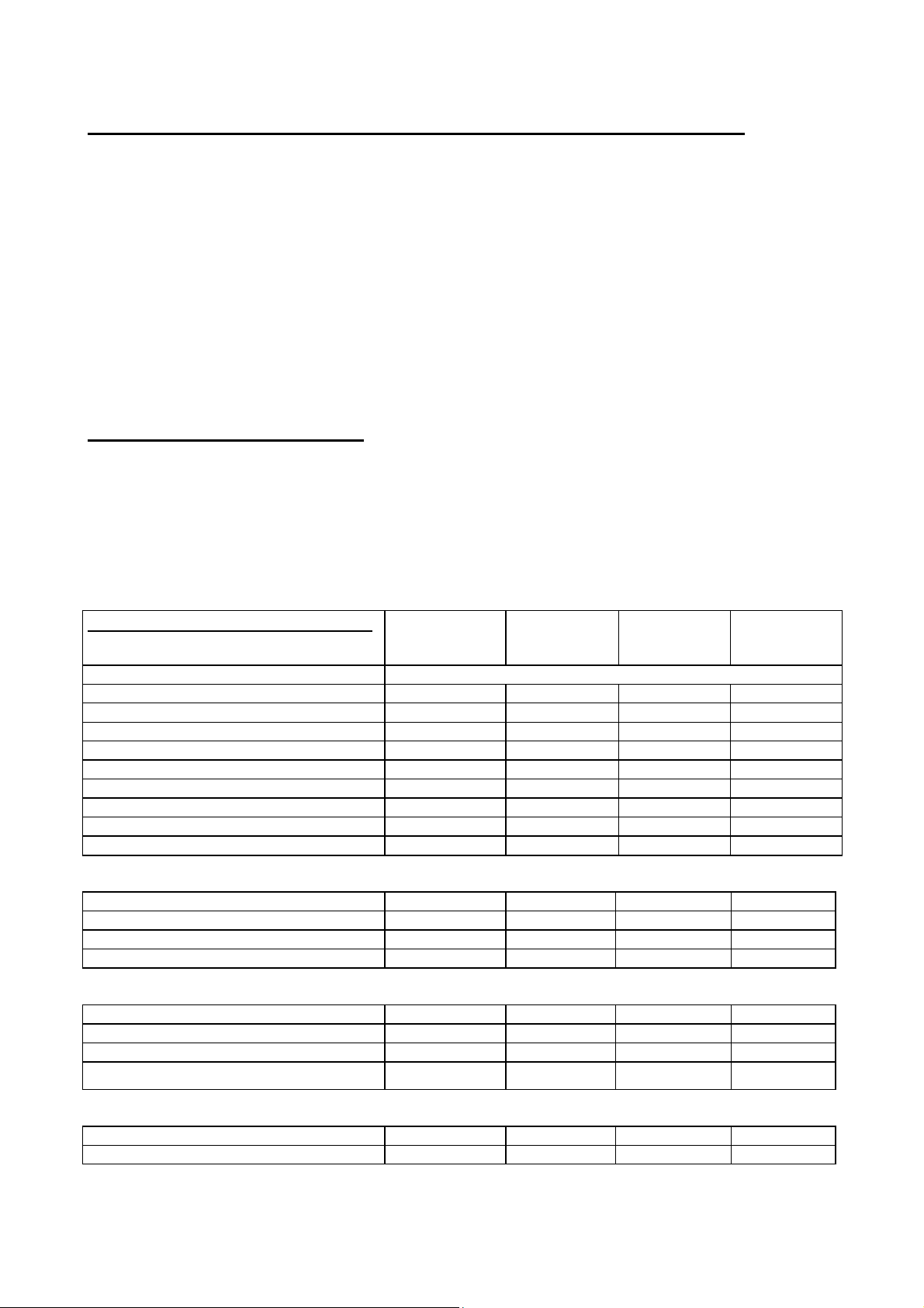
DATOS TÉCNICOS DE LOS QUEMADORES A GAS DEL HORNO
Tipo de Horno Pres. del Gas Inyector (mm)
Quemador gas kW Nat. / But. / Prop. Nat. / But. / Prop. by-pass (mm)
G20 G30/G31 G20 G30/G31 G20 G30/G31
Horno 60
Grill 60
Horno 70
Horno 90
Grill 90
2.20 20 30/37 110 70 reg. 0.40
2.10 20 30/37 110 72 - -
2.20 20 30/37 110 70 reg. 0.40
3.30 20 30/37 130 85 reg. 0.52
3.30 20 30/37 130 85 - -
DIMENSIONES EXTERNAS
Modelo Ancho (cm) Alto (cm) Profundidad (cm)
FI 60 60 60 55
FI 70 70 60 55
FI 90 89 60 55
DATOS TÉCNICOS DEL HORNO
VOLTAJE 220 – 230 – 240 V ~ 50/60 Hz
POTENCIA ELÉCTRICA TOTAL 2.2 kW 2.2 kW 2.6 kW 110 W
QUEMADOR GRILL GAS 2.1 kW / 3.2 kW
QUEMADOR GAS 2.2 kW 2.2 kW 3.3 kW 3.3 kW
RESIST. ELÉCTRICA GRILL 1.8 kW 1.8 kW 2.5 kW /
LÁMPARA DEL HORNO 25 W 25 W 25 W 25 W
VENTILADOR HORNO 25 W 25 W 25 W 25 W
VENTILADOR TANGENCIAL 25 W 25 W 25 W 25 W
MOTOR RUSTE-POLLOS 5 W 5 W 1 – 5 W 1 – 5 W
DIMENSIONES INTERNAS DE LA CAMARA DE COCCIÓN DEL HORNO
ALTO 300 mm 315 mm 310 mm 300 mm
ANCHO 420 mm 545 mm 710 mm 710 mm
PROFUNDIDAD 420 mm 415 mm 410 mm 410 mm
VOLUMEN ÚTIL 54 lt. 71 lt. 90 lt. 88 lt.
CONSUMO ENÉRGETICO
Consumo con gas Natural, G20 210 l/h 210 l/h 315 l/h 315 l/h
Consumo con GPL, G30 160 g/h 160 g/h 240 g/h 240 g/h
Consumo Gas Total 2.2 kW/h 2.2 kW/h 3.3 kW/h 3.3 kW/h
AREA de COCIÓN CON GRILL 726 cm² 726 cm² 1100 cm² 1100 cm²
FI S(X)60 GET /
GEVT / GGVT
HORNO GAS
FI S(X)70
GEVT
HORNO GAS
FI S(X)90
GEVT
HORNO GAS
FI S(X)90
GGVT
HORNO GAS
ACCESORIOS HORNO
Bandeja del horno Si Si Si Si
Parrilla int. Horno, 4 posiciones parrilla Si Si Si Si
18 VITROKITCHEN 12-2007 CE HORNO GAS.doc
Page 19
Este producto es conforme a la Directiva EU 2002/96/EEC.
El símbolo del cubo de basura cruzado grabado sobre un aparato indica que
el producto, al final de la vida útil del mismo, debe ser tratado separadamente
de los residuos domésticos, y debe de ser tratado en un centro de reciclaje
para aprovechar los elementos eléctricos y electrónicos o bién devolver al
vendedor en el momento de la adquisición de un aparato nuevo equivalente.
El cliente está a cargo de la cesión del aparato al final de su vida útil, para
poder aprovechar sus componentes y reciclarlos, con sanciones previstas en
la legislación vigente en materia de residuos.
El adecuado aprovechamiento y reciclaje de sus componentes, y tratamiento
de todas las piezas posibles de reciclarse se debe realizar para contribuir al
sostenimiento compatible y evitar en lo posible los efectos negativos en el
medio ambiente y así favorecer la salud y el aprovechamiento de los
materiales con los que está fabricado este producto.
Para una información mas detallada del sistema de reciclaje disponible,
dirigirse al servicio local de aprovechamiento de residuos, o en su
establecimiento habitual.
EL FABRICANTE DECLINA CUALQUIER RESPONSABILIDAD CIVIL O
PENAL, SI LA INSTALACIÓN NO SE HA REALIZADO SEGÚN LAS
NORMAS VIGENTES, EN CUANTO ESTÁ INDICADO EN ESTE MANUAL
DE INSTRUCIONES.
Este horno está fabricado conforme a las directrices de las directivas
comunitarias CEE 87/308; 73/23; 93/68, 89/336, 30.1.1 y 30.1.2
19 VITROKITCHEN 12-2007 CE HORNO GAS.doc
Page 20
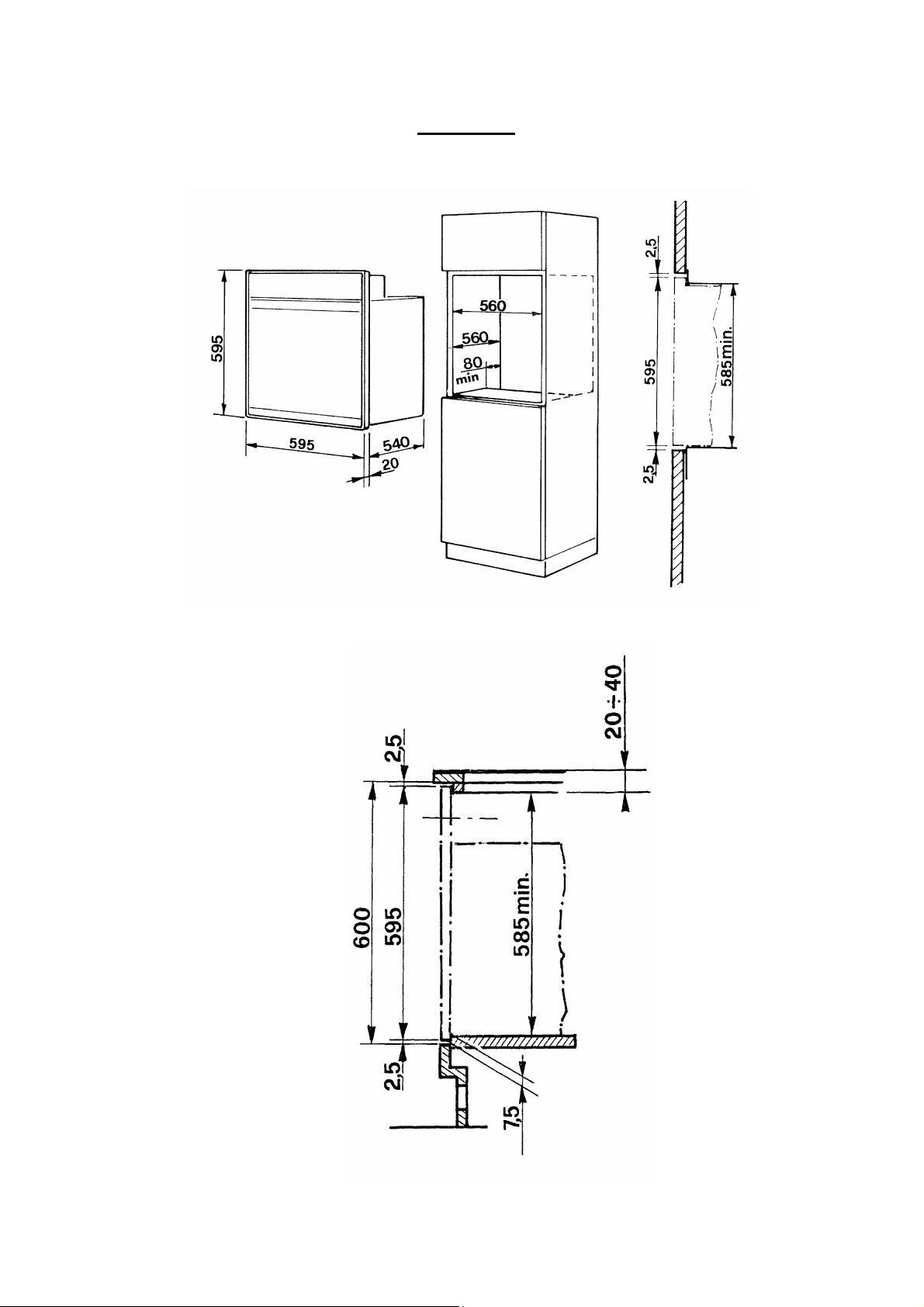
FIGURAS
20 VITROKITCHEN 12-2007 CE HORNO GAS.doc
Fig. 01A
Page 21
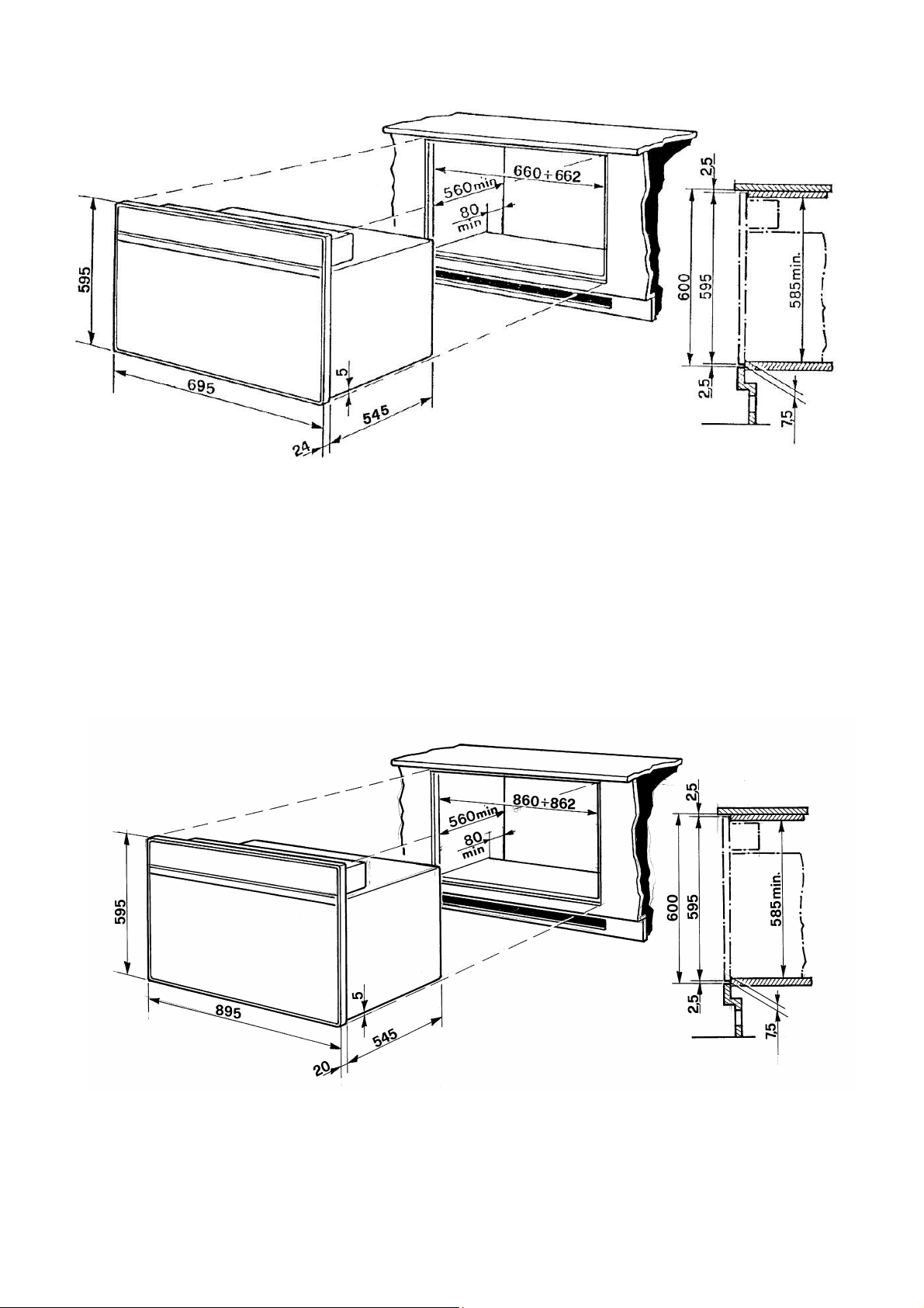
Fig. 01B para FI 70 Horno encastrable.
Fig. 01C para FI 90 Horno encastrable.
21 VITROKITCHEN 12-2007 CE HORNO GAS.doc
Page 22
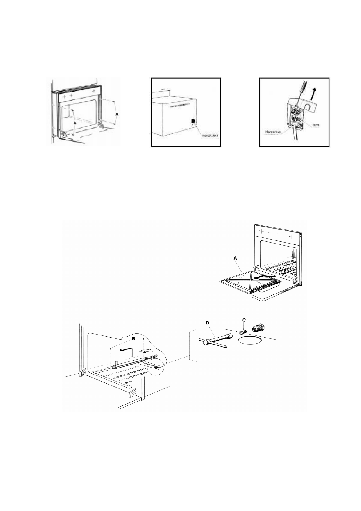
Fig. 02 Fig. 03 Fig. 04
Fig. 05
22 VITROKITCHEN 12-2007 CE HORNO GAS.doc
Page 23
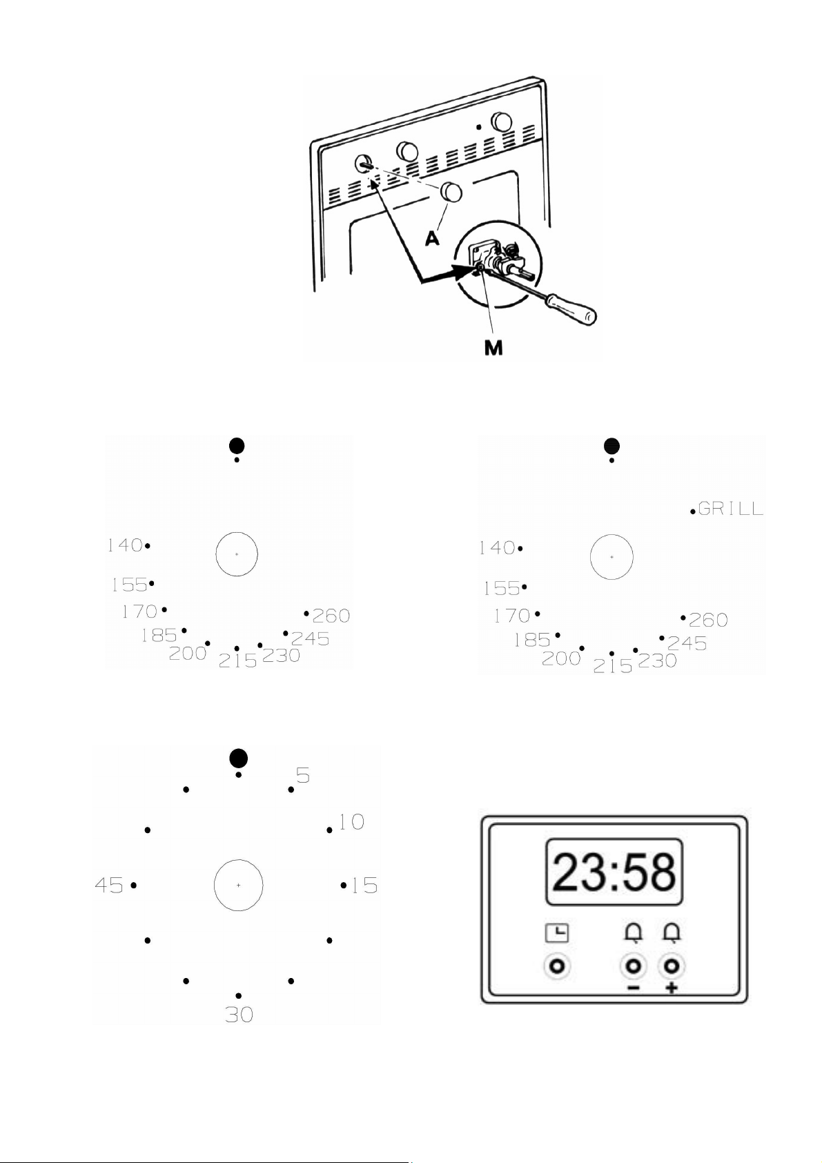
Fig. 06
Fig. 07A Fig. 07B
Fig. 08 Fig. 09
23 VITROKITCHEN 12-2007 CE HORNO GAS.doc
Page 24
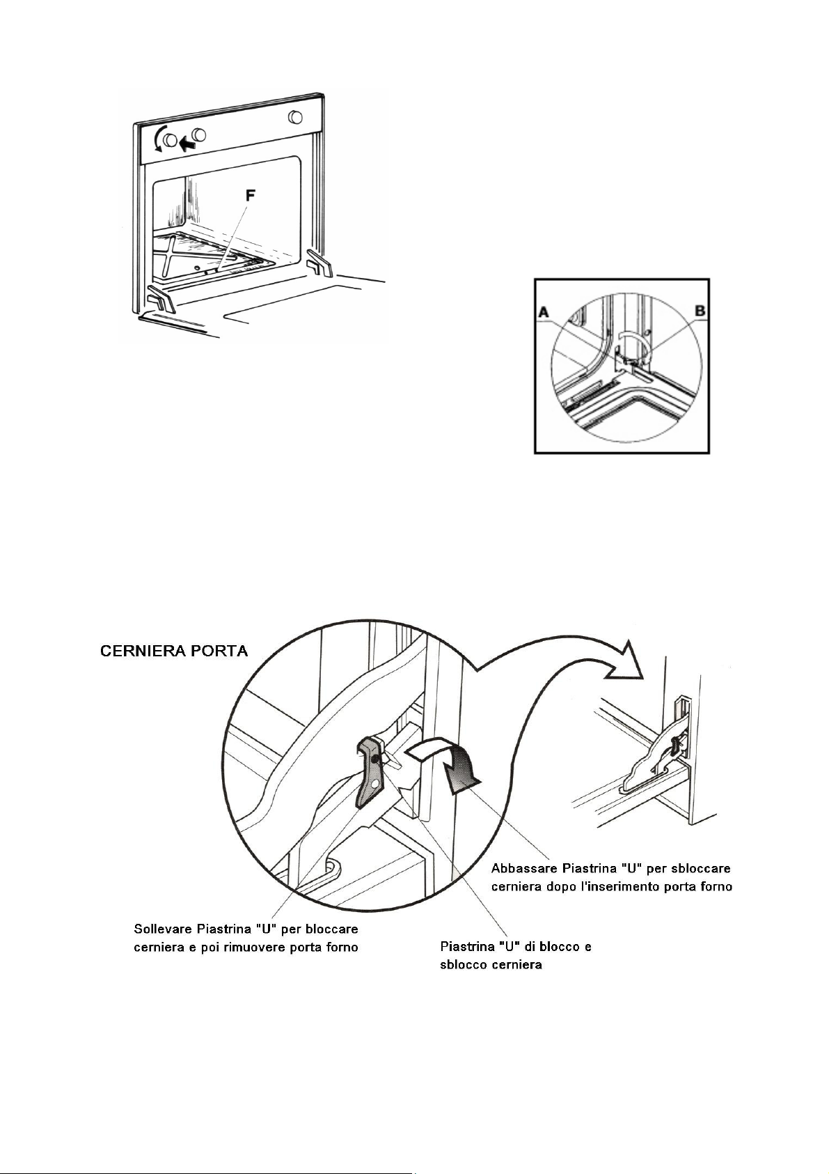
Fig. 10
Fig. n° 11A
Fig. n° 11B
24 VITROKITCHEN 12-2007 CE HORNO GAS.doc
Page 25
BUILT-IN
MODELS:
FI L(X)315 GE
GAS OVEN
FI N(X)900 GE
FI S(X)60 GEVT
FI S(X)60 GGVT
FI S(X)70 GEVT
FI S(X)90 GEVT
FI S(X)90 GGVT
INSTALLATION,
USE AND CARE INSTRUCTIONS
1 9880016900 E 05-2007 CE GAS OVEN
Page 26

INDEX: page
IMPORTANT SAFETY INSTRUCTIONS 3
IMPORTANT POINTS TO FOLLOW 3
INSTALLATION INSTRUCTION 5
BUILT-IN OVEN TO CABINET UNIT 5
CHARACTERISTICS OF CABINET UNIT 5
OVEN ELECTRICAL CONNECTION 6
GAS SUPPLY 7
GAS CONVERSION 9
GAS BURNER INJECTOR CONVERSION 9
LOW SETTING VALVE ADJUSTMENT 9
OVEN BURNER TECHNICAL DATA 10
OVEN TECHNICAL DATA 10
INSTRUCTION GUIDE FOR GAS OVEN 11
BAKE GAS BURNER USE 11
GRILL GAS BURNER USE 11
SELECTOR SWITCH 11
MINUTE MINDER 12
ELECTRONIC TIMER 12
OVEN RACK PLACEMENT 14
MAINTENANCE - OVEN CLEANING 14
OVEN DOOR 15
REPLACING THE OVEN LIGHT 16
SPARE PARTS 16
FIGURES 17 – 21
2 9880016900 E 05-2007 CE GAS OVEN
Page 27

IMPORTANT: SAVE THESE INSTRUCTIONS.
IMPORTANT SAFETY INSTRUCTIONS
Read and follow all instructions before using this appliance to prevent
the potential risk of fire, electrical shock, personal injury or damage to the
appliance as a result of improper usage of the appliance.
WARNING: If the information in this manual is not followed exactly, a
fire or explosion may result causing property damage, personal injury
or death.
Do not store or use gasoline or other flammable vapours and liquids in
the vicinity of this appliance.
WHAT TO DO IF YOU SMELL GAS:
- Do not to light any appliance.
- Do not touch any electrical switch.
- Do not use any phone in your building.
- Immediately call your gas supplier from a neighbour’s phone. Follow
the gas supplier’s instructions.
- If you cannot reach your gas supplier, call the fire department.
Installation and service must be performed by a qualified installer,
service agency or the gas supplier.
To ensure proper and safe operation: Appliance must be properly installed
and grounded by a qualified installer. Have the installer show you the location
of the gas shut off valve and how to shut it off in an emergency.
Always disconnect power to appliance before servicing.
CAUTION: DO NOT LIFT OR MOVE OVEN BY DOOR HANDLES.
IMPORTANT POINTS TO FOLLOW.
Proper installation. Be sure your appliance is properly installed and grounded
by a qualified technician.
Never use your appliance for warming or heating the room.
3 9880016900 E 05-2007 CE GAS OVEN
Page 28

Do Not leave children alone. Children should not be left alone or unattended
in area where appliance is in use. They should never be allowed to sit or
stand on any part of the appliance.
User servicing. Do not repair or replace any part of the appliance unless
specifically recommended in the manual. All other servicing should be
referred to a qualified technician.
Storage in appliance. Flammable materials should not be stored in the oven.
Do Not use water on grease fires. Smother fire or flame by using dry chemical
or foam-type extinguisher.
Use only dry potholders. Moist or damp potholders on hot surfaces may result
in burns from steam. Do not let potholder touch gas burners. Do not use a
towel or other bulky cloth.
Glazed cooking utensils. Only certain types of glass, glass/ceramic, ceramic,
earthenware, or other glaze utensils are suitable for cooking range use
without breaking due to the sudden change in temperature.
Do Not touch oven gas burner or interior oven surface. Surface oven gas
burners may be hot even though they have no flame. Areas near surface
interior oven surfaces may become hot enough to cause burns. Make sure
hot areas have had sufficient time to cool, before touching them.
Use care when opening door. Let hot air or steam escape before removing or
replacing food.
Do not heat unopened food containers. Build-up of pressure may cause
container to burst and result in injury. Keep oven vent ducts unobstructed.
Placement of oven racks. Always place oven racks in desired location while
oven is cool. If rack must be moved while oven is hot, do not let potholder
contact hot surfaces in oven.
4 9880016900 E 05-2007 CE GAS OVEN
Page 29

INSTALLATION INSTRUCTIONS
SPECIAL WARNING:
ONLY QUALIFIED PERSONNEL SHOULD INSTALL OR SERVICE THIS
APPLIANCE.
READ “SAFETY INSTRUCTIONS” IN THIS BOOK BEFORE USING THIS
APPLIANCE.
IMPROPER INSTALLATION, ADJUSTMENT, ALTERATION, SERVICE,
MAINTENANCE OR USE OF RANGE CAN RESULT IN SERIOUS INJURY
OR PROPERTY DAMAGE.
This appliance must be installed in accordance with the manufacturer’s
installation instructions.
CAUTION: DO NOT LIFT OR MOVE OVEN BY DOOR HANDLES.
BUILT-IN OVEN TO CABINET UNIT:
The oven may be built-in either in a column or under countertop of a suitable
cabinet unit.
Cut-out opening dimensions to be performed on cabinets are indicated in
fig. 1A, 1B and 1C. Make sure cabinet unit in which the oven is to be fitted is
sufficiently sturdy to take the weight of the appliance, approx. 35 Kg. for mod.
FI 60 and 50 Kg. for mod. FI 70 and FI 90. On the bottom of the unit and/or
on the shelf supporting the oven, remember to do the cut-out section at the
back, see fig. 1A and 1B, to allow fresh air passage for appliance cooling.
Ensure that the oven is firmly fixed on provided cut-out. Use screws “A” fig. 2,
to secure oven.
CHARACTERISTICS OF CABINET UNIT: Cabinet Unit technical
requirements as follow;
- The unit and its components must be able to resist a temperature of 90°C
without becoming unglued or warped.
- The unit must allow free passage of the electrical connections as well as
gas tubing in case is needed.
CAUTION: SOME CABINETS AND BUILDING MATERIALS ARE NOT
DESIGNED TO WITHSTAND THE HEAT PRODUCED BY THE NORMAL
SAFE OPERATION OF A LISTED APPLIANCE. DISCOLORATION OR
DAMAGE, SUCH AS DELAMINATION, MAY OCCUR.
5 9880016900 E 05-2007 CE GAS OVEN
Page 30

VENTILATION
Ventilation must be in accordance with local installation code. The appliance
must be install in a well-ventilated environment to guarantee a correct
combustion gases exchange, proper air circulation and working temperature
within safety limits.
ATTENTION: In case of appliance failure you must contact the after
service authorised person.
MODEL NUMBER PLATE
The Model Number Plate is located on the underneath case. A second Model
Number Plate is applied on the front page of the instruction booklet.
OVEN ELECTRICAL CONNECTION
IMPORTANT.
- This appliance must be connected to power supply only by a skilled
authorised personal.
- Electrical connection must comply with requested local product electrical
standard requirements.
- It must be powered by a single-phase 220 – 230 – 240 V ~ 50/60 Hz
electrical connection, verify Product Label for correct electrical power voltage
and frequency input.
EARTH OR GROUND CONNECTION IS MANDATORY.
- If electrical wiring is made directly to wall outlet, it is necessary to apply a
breaker type of switch suitable to appliance electrical power and standard
requirements.
- IN ANY TIME, GROUND WIRING MUST NOT BE INTERRUPTED BY A
SWITCH OR SIMILAR COMPONENT.
THE APPLIANCE MUST ALWAYS BE DISCONNECTED FROM POWER
SUPPLY BEFORE PERFORMING ANY MAINTENANCE AND SETTINGS.
This appliance is supplied with an electrical flexible cord without plug. In case
of plug application, use a suitable plug in accordance to the appliance
technical specifications. Remember to properly connect the ground or
yellow/green wire to the plug’s ground lead
In case of flexible cord replacement or application, read following instruction:
- Disconnect electrical power supply.
- Open terminal block cover (fig. 3 - 4).
- Fix flexible cord leads properly as indicated in figure 4, Brown Hot (L),
Neutral (N) and Ground. Remember the yellow-green lead is ground. If a 13A
(BS. 1363) plug is used, fit a 13 amp fuse.
6 9880016900 E 05-2007 CE GAS OVEN
Page 31

- The flexible cord must always be secured by the cord clamp (fig. 4) on
terminal block, so may not become loose by being pulled accidentally. Also,
make sure flexible cord does not touch hot point of over 75 °C through out the
entire cord length.
- Electrical plug must be suitable to appliance purpose, as mentioned before.
Also, position the plug in a location accessible after appliance installation,
unless the appliance incorporates or is connected to a switch that ensures allpole disconnection. This type of switch must have a contact separation in all
poles of not less than 3 mm.
ATTENTION: Use only electrical flexible cord with three-prong assembly, for
all Single Gas ovens use type H05RR-FH 3 x 0.75 or H05RR-FH 3 x 1.5 for
GET and GEVT models.
GAS SUPPLY
GAS SUPPLY CONNECTION:
A TRAINED SERVICEMAN OR GAS APPLIANCE INSTALLER MUST
MAKE THE GAS SUPPLY CONNECTION. Leak testing of the appliance
shall be conducted by the installer according to the instructions given
in section (h).
In case of using Natural gas, supply line must have an inlet pressure of
20 mbar. In case of Liquefied Petroleum L.P. / Propane gas, supply line must
have an inlet pressure of 30/37 mbar. Make sure gas pressure does not
exceed 50 mbar. otherwise it can damage the appliance gas components and
can result in a gas leak.
a) A gas cut-off valve should be put in an accessible location in the supply
line ahead of the oven, for turning on and turning off gas supply. If oven is
to be connected to house piping with flexible or semi-rigid metal
connectors for gas appliances, connector’s nuts must not be connected
directly to pipe threads. The connectors must be installed with adapters
provided with the connector.
b) The house piping and/or oven connector used to connect the oven to the
main gas supply must be clean, free of metal shavings rust, dirt and liquids
(oil or water). Dirt in the supply lines can work its way into the oven
manifold and in turn cause failure of the gas valves or controls and clog
burners and/or orifices.
7 9880016900 E 05-2007 CE GAS OVEN
Page 32

c) Turn off all pilots and main gas valve of other gas appliances.
d) Turn off main gas valve at meter.
e) Before connecting oven apply pipe thread compound approved for LPG to
all threads.
f) Connect oven to gas supply using adapters supplied with flexible
connector. Rigid pipe may also be used. See rating plate for type of gas to
which the oven has been manufactured for.
g) Turn on main gas valve at meter, and relight pilots at other gas
appliances.
h) Apply a non-corrosive leak detection fluid to all joints and fittings in the gas
connection between the supply line shut-off valve and the range. Include
gas fittings and joints in the range if connections were disturbed during
installation. Check for leaks!. Bubbles appearing around fittings and
connections will indicate a leak. If a leak appears, turn off supply line gas
shut-off valve, tighten connections, turn on the supply line gas shut off
valve, and retest for leaks.
CAUTION: NEVER CHECK FOR LEAKS WITH A FLAME.
WHEN LEAK CHECK IS COMPLETE, WIPE OFF ALL RESIDUE.
i) Remove shipping polystyrene from cooking cavity. This is to hold the racks
in place in the cooking cavity for shipping purposes only.
CHECKING PRESSURE OF HOUSE PIPING SYSTEM
1) The appliance and its individual shutoff valve must be disconnected from
the gas supply piping system during any pressure testing of that system at
test pressure in excess of 35 mbar.
2) The appliance must be isolated from the gas supply piping system by
closing its individual manual shutoff valve during any pressure testing of
the gas supply piping system at test pressure equal to or less than
35 mbar.
8 9880016900 E 05-2007 CE GAS OVEN
Page 33

GAS CONVERSION
All gas ovens are equipped with both Natural Gas and LP Gas injectors. The
unit model number plate states which gas it was adjusted for at the factory.
To convert the unit to either Natural gas or LP gas will require switching
burner injectors, burner adjustment for low flame and adjustment of the
appliance pressure regulator converter cap.
Inlet pressure to the appliance should be as follows for both operation and
checking of appliance pressure regulator setting:
INLET PRESSURE IN mbar.
PRESSURE
Minimum Maximum
Natural gas 18 20
LP gas 28/35 30/37
GAS BURNER INJECTOR CONVERSION
To switch injectors, it is enough to unscrew fixed injector using a proper
7 Hex. key tool and replace it with new injector for new gas setting.
For proper injector size, follow Oven Technical Data chart.
On Gas Oven Burners, it is not necessary to adjust burner air shutter.
Make sure the flame does not lift or blow off the burner when cold. Also in
case of excessive yellow flame on burner, call technical assistance to control
the appliance. Please see figure 5.
LOW SETTING VALVE ADJUSTMENT
The LOW setting should produce a stable flame when turning the knob from
HIGH to LOW. The flame should be stable on all ports on LOW setting.
To adjust: Operate burner on HIGH (290 °C)for about five minutes to preheat
burner itself. Turn knob back to LOW (150 °C); remove knob, and insert a
small flat tip screwdriver into the slotted area on the left centre of the valve
stem. Adjust the flame size by turning adjustment screw in either direction,
while holding the stem (figure 6).
NOTE: All gas adjustment should be done by a qualified service
personnel only.
9 9880016900 E 05-2007 CE GAS OVEN
Page 34
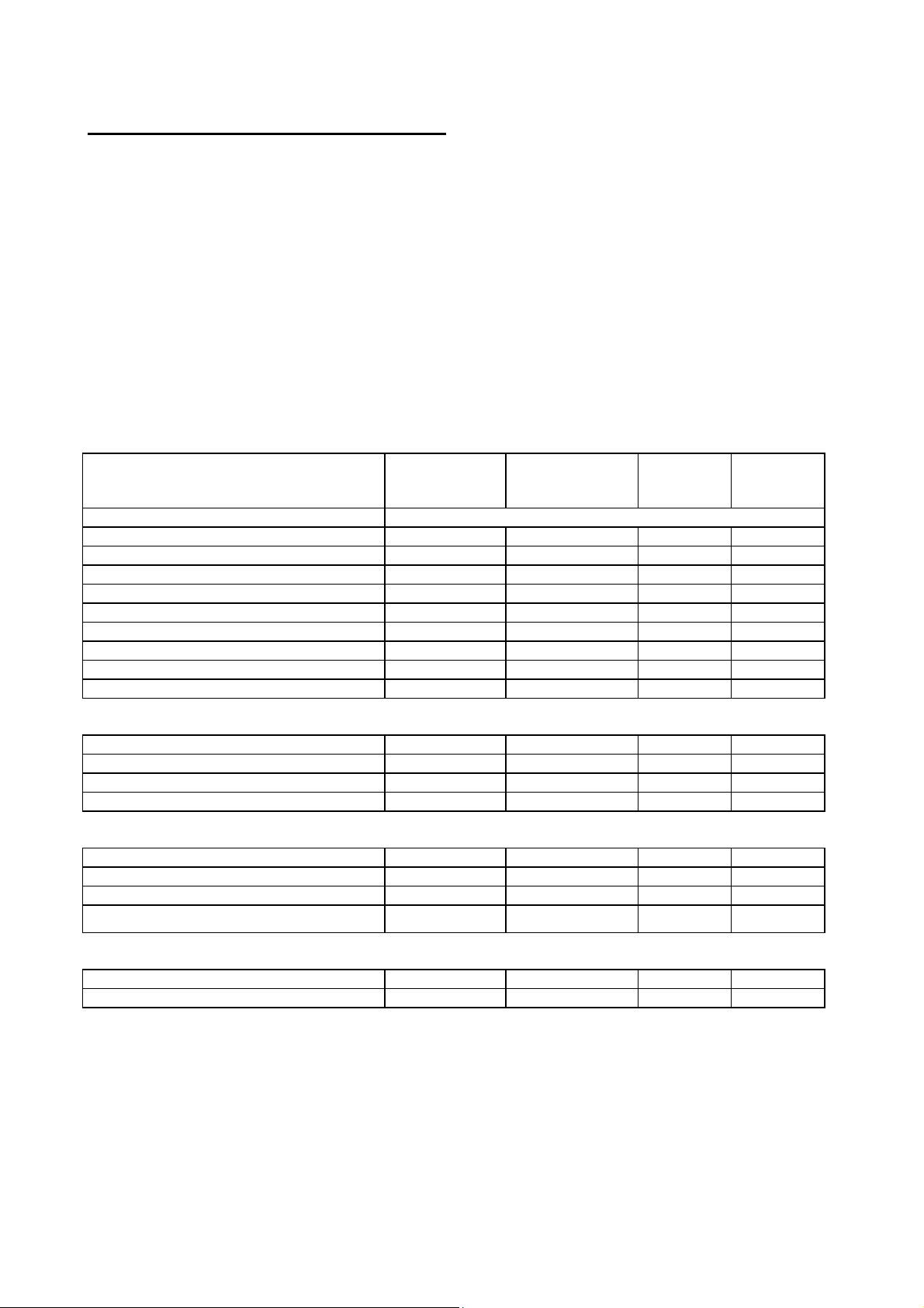
OVEN BURNER TECHNICAL DATA
Burner kW Gas Press. Gas Orifice (mm)
Nat. / But. / Prop. Nat. / But. / Prop. by-pass (mm)
G20 G30/G31 G20 G30/G31 G20 G30/G31
Oven 60 2.20 20 30/37 110 70 reg. 0.40
Grill 60 2.10 20 30/37 110 72 - -
Oven 70 2.20 20 30/37 110 70 reg. 0.40
Oven 90 3.30 20 30/37 130 85 reg. 0.52
Grill 90
3.30 20 30/37 130 85 - -
OVEN TECHNICAL DATA
ELECTRICAL DATA
VOLTAGE 220 – 230 – 240 V ~ 50/60 Hz
TOTAL POWER 2.2 kW 2.2 kW 2.6 kW 110 W
GRILLING GAS BURNER 2.1 kW / 3.2 kW
BOTTOM GAS BURNER 2.2 kW 2.2 kW 3.3 kW 3.3 kW
ELECTRIC GRILL 1.8 kW 1.8 kW 2.5 kW /
OVEN LIGHT 25 W 25 W 25 W 25 W
CONVECTION FAN 25 W 25 W 25 W 25 W
COOLING FAN (IF INSTALLED) 25 W 25 W 25 W 25 W
ROTISSERIE MOTOR 5 W 5 W 1 – 5 W 1 – 5 W
USEFUL OVEN INTERIOR DIMENSIONS
HEIGHT 30 cm 31.5 cm 310 mm 300 mm
WIDTH 42 cm 54.5 cm 710 mm 710 mm
DEPTH 42 cm 41.5 cm 410 mm 410 mm
OVERALL SIZE 54 lt. 71 lt. 90 dm³ 88 dm³
ENERGY POWER PERFORMANCE
Consumption with Natural Gas G20 210 l/h 210 l/h 315 l/h 315 l/h
Consumption with LPG G30 160 g/h 160 g/h 240 g/h 24 0 g/ h
Total consumption 2.2 kW/h 2.2 kW/h 3.3 kW/h 3.3 kW/h
BROILING AREA 726 cm² 726 cm² 1100 cm² 1100 cm²
FI S(X)60 GET /
GEVT / GGVT
GAS OVEN
FI S(X)70
GEVT
GAS OVEN
FI S(X)90
GEVT
GAS OVEN
FI S(X)90
GGVT
GAS OVEN
OVEN ACCESSORIES
One Dripping Tray Yes Yes Yes Yes
One Cooking Rack, four rack positions Yes Yes Yes Yes
DIMENSIONS OF THE APPLIANCES
Series Width (cm) Height (cm) Depth (cm)
FI S(X)60 60 60 55
FI S(X)70 70 60 55
FI S(X)90 89 60 55
10 9880016900 E 05-2007 CE GAS OVEN
Page 35

INSTRUCTION GUIDE FOR GAS OVEN
BAKE GAS BURNER USE
Open the oven door completely, and them push in and turn the thermostat
knob anticlockwise to 260 °C setting. See fig. 07A, 07B and 08. A clicking
sound will be heard and the burner will light. Look through orifice “F” for
burner ignition. Keep pushing knob to allow thermocouple of safety device to
warm up enough, for about a period of 10 seconds. Then release the knob
and turn it to desired temperature setting.
Attention: During ignition of a newly installed oven and after a long period of
inactivity, the gas burner may not ignite at once, so try again till gas comes
out to allow ignition, wait a few seconds before trying again to allow excess of
gas to dissipate. If problem persist, call an authorised technician for
assistance.
GRILL GAS BURNER USE
Set thermostat to Grill mode by turning knob clockwise. See fig. 07B.
Follow bake gas burner ignition procedure paragraph. Once grill burner is on,
allow a period of time for preheating the oven cavity before grilling food.
IMPORTANT: LEAVE OVEN DOOR OPEN WHILE GRILLING. MAXIMUM
GRILLING TIME IS 15 MINUTES
SELECTOR SWITCH
This control allows you to turn on the Oven Internal Light or Rotisserie.
See fig. 9.
OVEN LIGHT ; (all models)
Use this setting to turn on Oven light, light also remains on in all
other modes.
ROTISSERIE ; (all models)
Use this function to broil or roast food using the rotisserie. To use
the rotisserie you must preheat the oven using the Grill gas
burner. Insert spit with food in the slotted shaft on the back oven
wall, then use front support to keep in place the rotisserie spit
and apply cooking tray below the rotisserie spit as a grease
retainer. Remember to take off the rotisserie handle before
closing oven door. For Grilling procedure follow Grill Use
chapter.
11 9880016900 E 05-2007 CE GAS OVEN
Page 36
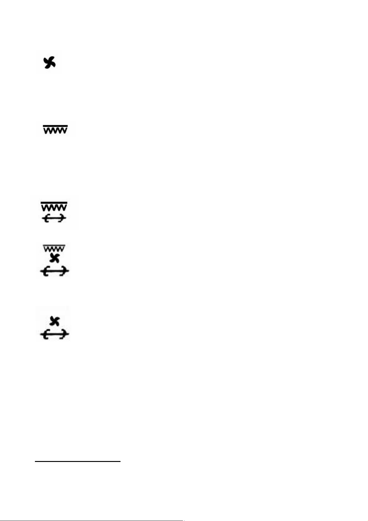
CONVECTION FAN OR DEFROST ; (GGVT; GEVT only)
Use this setting when Convection is necessary for a
more even cooking finish. Also, use this setting to defrost frozen
food by speeding up air circulation. This function can not be used
while using the grill gas burner.
ELECTRIC GRILL; (all models)
This function operates the full top heating element. This element
is used for browning the food and can also be used at the end of a
normal cooking period to give extra browning to dishes or give a
crisper finish to meat. Pre-heat this function before cooking. Grill
for a maximum period of 15 minutes and keeping oven door open.
ELECTRIC GRILL WITH ROTISSERIE; (all models)
Grill for a maximum period of 15 minutes and keeping oven door
open.
GRILL with CONVECTION FAN and ROTISSERIE (GEVT only)
U select this setting to combine the intense heat from the inner top
element with the convection fan. This air circulation crisps the
exterior surface and retains inner moisture in thick cuts of meat.
Also with function allows you to use the Rotisserie spit. Grill for a
maximum period of 15 minutes and keeping oven door open.
CONVECTION FAN (DEFROST) AND ROTISSERIE.
(GGVT; GEVT only).
This function allows you to defrost food using the rotisserie.
ON AND OFF PILOT LIGHT
Whenever Rotisserie function is selected, the red light goes on.
MINUTE MINDER
Set required time by turning knob clockwise. As the time set elapses, a bell
signal will sound for a few seconds. This timer has only the function of time
reminder. It does not stop the oven functions. See fig. 10.
ELECTRONIC TIMER
After first electrical power on and in case of any electrical power failure and
power has been restored, the electronic timer will start flashing. Fig. 03.
12 9880016900 E 05-2007 CE GAS OVEN
Page 37

TO SET TIME OF DAY
Press button. Set time of day with “+” and “-” buttons.
This function remains activated 7 seconds after the last “+” / “-” operation.
TO CHANGE TIME OF DAY
Press the button for 4 seconds until the hours display will flash.
Change the hours only by using the “+” or “-” button. The minutes and hidden
seconds will not be affected.
TO SET TIMER FUNCTION
This function will be activated with “+” button. Press “+” button again to
increase duration time.
During setting the count units are in 10 seconds steps or minutes.
During count down the timer has priority on the display. The bell-symbol
illuminated. The units are in seconds or minutes in the long time section.
The maximum time is 10h. The format change will happen after 99 minutes
and 50 seconds to 1 hour and 40 minutes.
To show time of day press
button, after 6 seconds, the count down
comes back on.
TO RESET TIMER
Count down to zero with permanent pressing “-” button (automatic stop at
zero).
SIGNAL
The signal after “time out” will stay 7 minutes if it has not been reset with
button. The following signal will be skipped if time of day is pressed
during the last 15 seconds of the timer.
SIGNAL FREQUENCY
If no function is activated, the signal frequency can be selected by pressing
the “-“ button. Three different frequencies are selectable.
13 9880016900 E 05-2007 CE GAS OVEN
Page 38

CAUTION:
1) Do not obstruct the flow of combustion and ventilation air by blocking the
room vents or air intakes. Restriction of air flow to the gas appliance prevents
proper performance and increases carbon monoxide emission to unsafe
levels.
2) If flame should go out during operation, turn the burner off. If a strong gas
order is detected, open a window and wait five minutes before relighting the
burner.
6) Be sure all control knobs are set in the OFF position prior to supplying gas
to the oven.
OVEN RACK PLACEMENT FOR SPECIFIC FOODS:
1) Frozen pies, large roast, turkey, angel food cakes, thick well-done meat
cuts; rack position is 1
st
or 2nd rack guide from the bottom.
2) Bundt cake, most quick breads, yeast breads, casseroles, meats, thick
meat cuts; rack position is 2
nd
rack guide from bottom.
3) Cookies, biscuits, muffins, cakes, non frozen pies, thin meat cuts; rack
position is 2
4) For Grilling food; rack position is 4
5) For Grilling toast bread; rack position is 5
nd
and 3rd rack guide from bottom.
th
rack guide from bottom.
th
rack guide from bottom.
MAINTENANCE
CLEANING SAFETY
Turn off all controls and wait for appliance parts to cool before touching or
cleaning them. Do not touch oven inner surface or surrounding areas until
they have had sufficient time to cool.
Clean appliance with caution. Use care to avoid steam burns if a wet sponge
or cloth is used to wipe spills on a hot surface. Some cleaners can produce
noxious fumes if applied to a hot surface.
SURFACE AND OVEN COOKING CAVITY CLEANING
This is easily done using a damp cloth and a non-abrasive detergent,
wipe using a soft dry cloth. For stainless steel parts with stubborn soils. Use
only plastic scrubbing pad or a sponge with vinegar and warm
water.
14 9880016900 E 05-2007 CE GAS OVEN
Page 39

Because of many new cleaning products introduced in the marketplace each
year, it is not possible to list all products that can be safely be used to clean
this appliance. Read carefully the cleaner manufacture’s instructions to be
sure the cleaner can be safely used on this appliance. Although, to determine
if a cleaning product is safe, test a small inconspicuous area using a very light
pressure to see if the surface may scratch or discolour. This particular
important for porcelain enamel, highly polished, shiny, painted or plastic
surfaces.
OVEN DOOR
TO REMOVE OVEN DOOR
1) Fully open the oven door.
2) Raise and open the U-clip (B) over the hook on each of the hinges (A) all
the way to the front, see figure 11A and 11B.
3) Grasp the door by the sides toward the back. Raise the front of the door a
few inches and make sure the U-clip (B) is locked by the door frame. This
will prevent the hinge from snapping closed when the door is removed.
(there will be some spring resistance to overcome because of the hinge
being locked). When the front of the door is high enough and hinges are
locked, you will be able to lift the hinges to clear the slots
4) Pull the hinges out of the slots in the oven front frame.
TO REPLACE THE OVEN DOOR
1) Grasp the sides of the door at the centre and insert the ends of the hinges
(A) and fix the slots in the oven front frame.
2) With the door open all the way, push-back the two U-clips (B) into the
hinge (A).
3) Raise the oven door and make sure that it fits evenly with the front sides.
WARNING: Never release the U-clip levers when the door is off. Do not close
the hinges without the weight of the door, the powerful springs will snap the
hinges closed with great force.
CAUTION: Do not place excessive weight on or stand on an open oven door.
This could cause the range to tip over, break the door, or injure the user.
Also, do not attempt to open or close door or operate oven until door is
properly replaced.
15 9880016900 E 05-2007 CE GAS OVEN
Page 40

REPLACING THE OVEN LIGHT
WARNING; To prevent electrical shock and or personal injury:
1) Before replacing the light bulb, be sure the electric power is turned off at
the circuit breaker.
2) Do not operate the oven unless the light cover is securely in position.
3) Be sure the oven and light bulb are cool.
4) Do not touch hot bulb with a damp cloth as this may cause the bulb to
break.
5) If the light cover is damaged or broken, do not use the oven until a new
cover is in place.
To replace oven light bulb:
1) Before replacing light bulb, disconnect oven electric circuit.
2) Remove oven racks.
3) Remove, unscrewing, lens bulb cover and light bulb.
4) Replace bulb with a 25 W – 230 Vac appliance bulb only.
5) Replace lens bulb cover.
6) Reconnect power to range. Reset electronic clock.
SERVICE – PARTS INFORMATION
When your appliance requires service or replacement parts, contact your
dealer or authorised service agency. Please give the complete model and
serial number of the appliance, which is located on the oven model number
plate
In our continuing effort to improve the quality and performance of our cooking
products, it may be necessary to make changes to the appliance without
revising this guide. The manufacturer does not take any responsibility on
booklet printing mistakes.
THE MANUFACTURER DECLINES ANY LEGAL AND WARRANTY
RESPONSIBILITY FOR NOT FOLLOWING INSTALLATION AND WIRING
INSTRUCTION IN ACCORDANCE WITH ELECTRICAL EUROPEAN
STANDARDS AS WELL AS APPLIANCE USER MISUSE.
16 9880016900 E 05-2007 CE GAS OVEN
Page 41
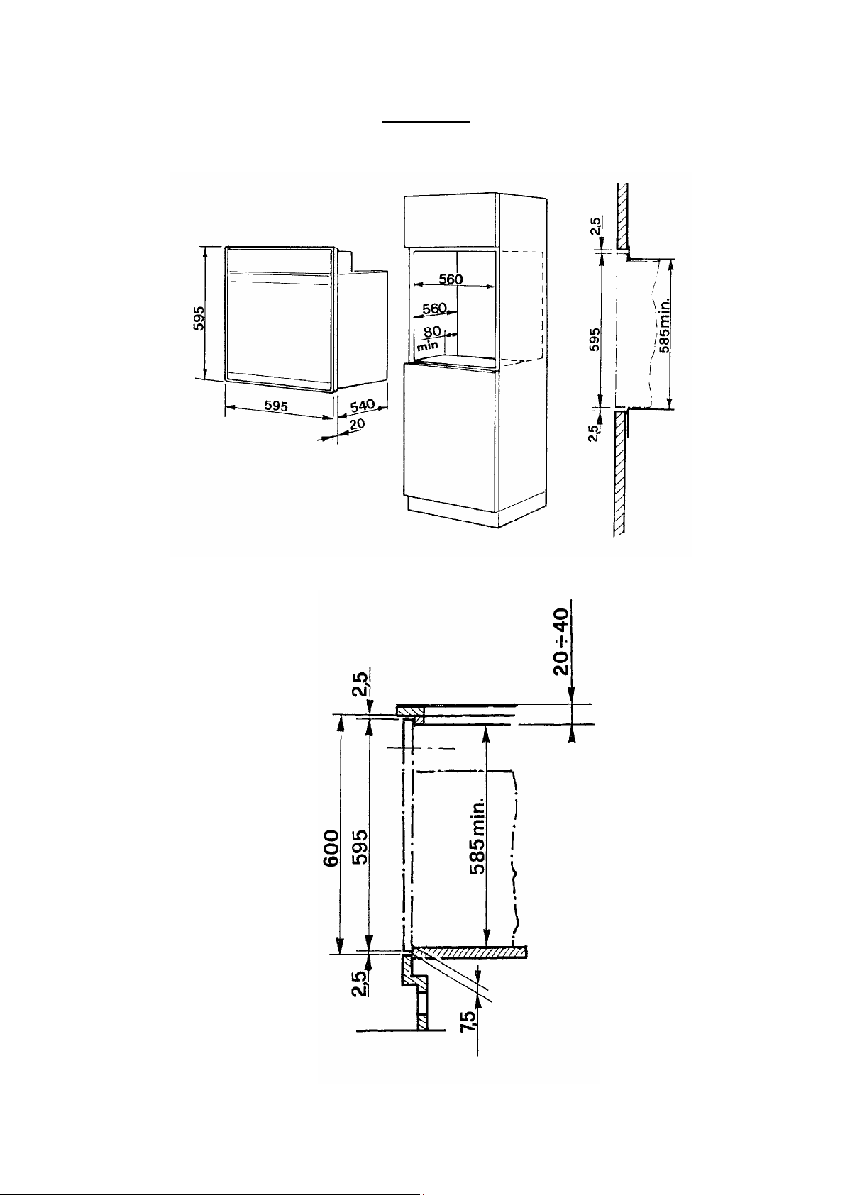
FIGURES
17 9880016900 E 05-2007 CE GAS OVEN
Fig. 1A
Page 42
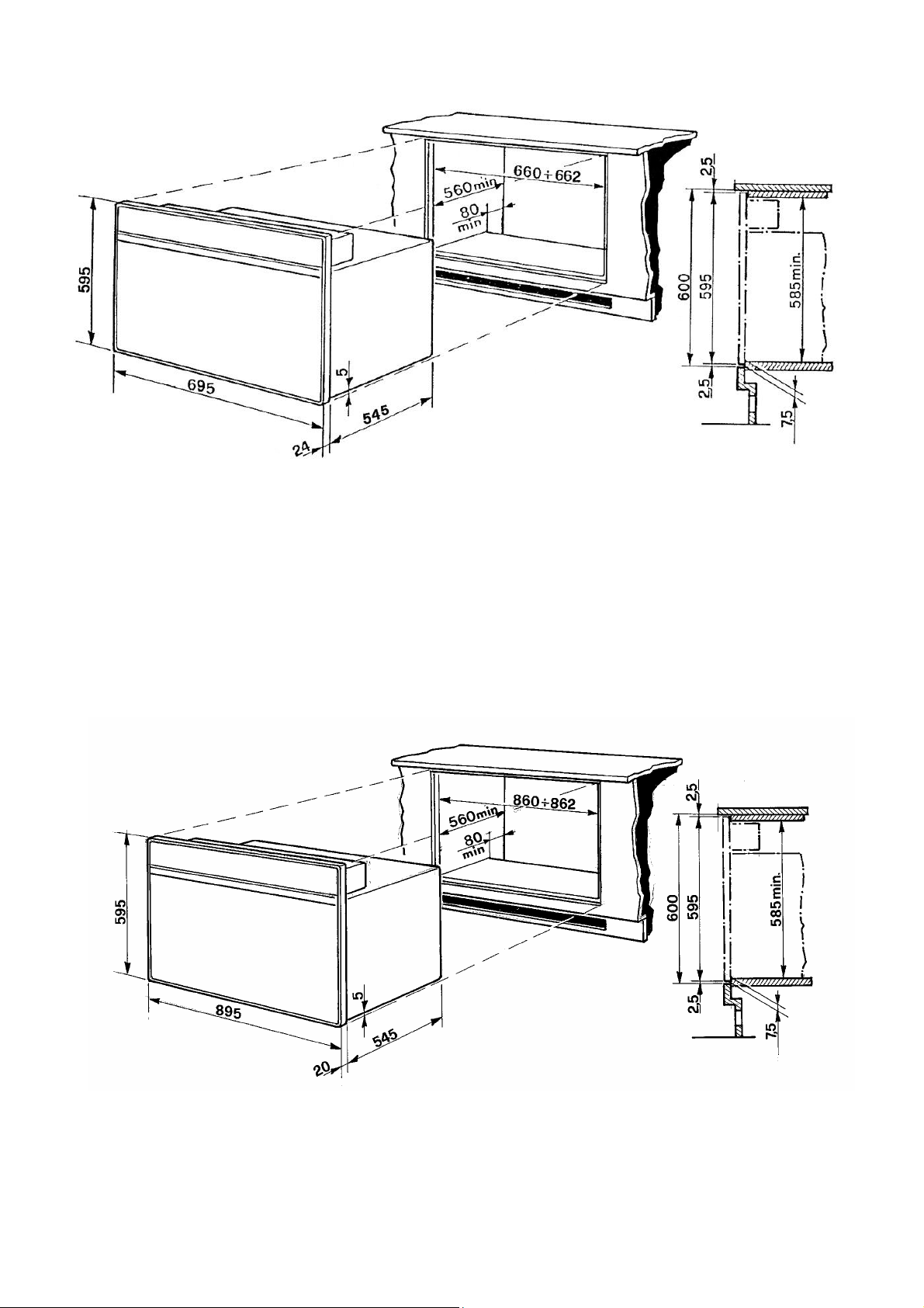
Fig. 1B for FI S(X)70 BUILT-IN OVEN
Fig. 1C for FI S(X)90 BUILT-IN OVEN
18 9880016900 E 05-2007 CE GAS OVEN
Page 43
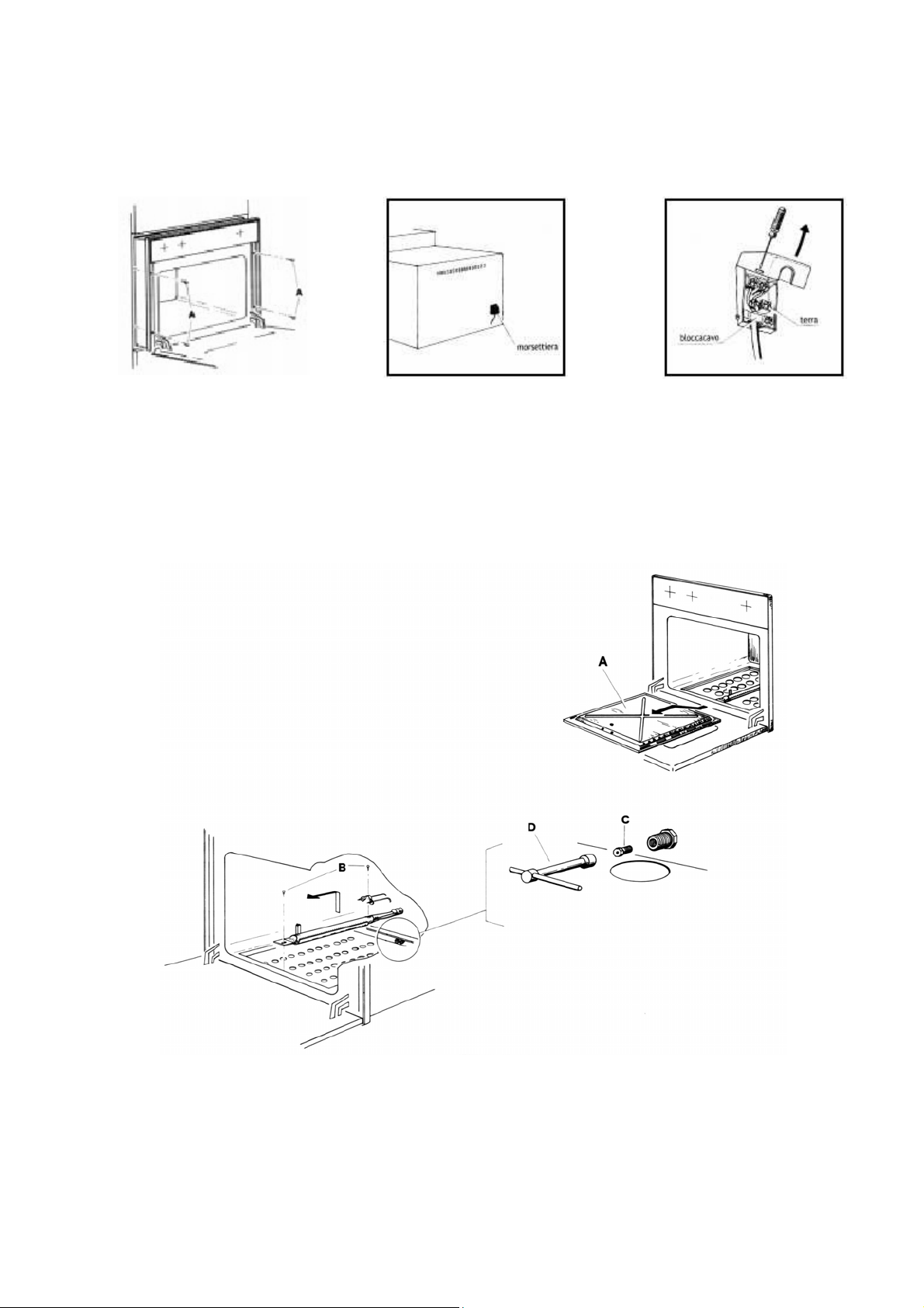
Fig. 2 Fig. 3 Fig. 4
Fig. 5
19 9880016900 E 05-2007 CE GAS OVEN
Page 44
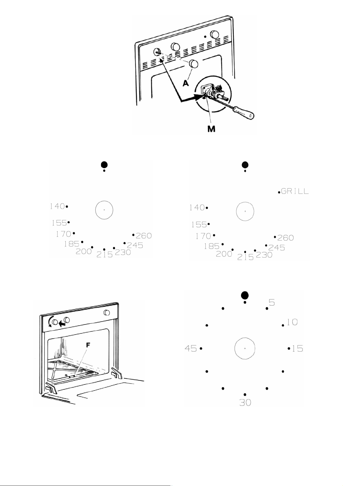
Fig. 6
Fig. 7A Fig. 7B
Fig. 8 Fig. 10
20 9880016900 E 05-2007 CE GAS OVEN
Page 45
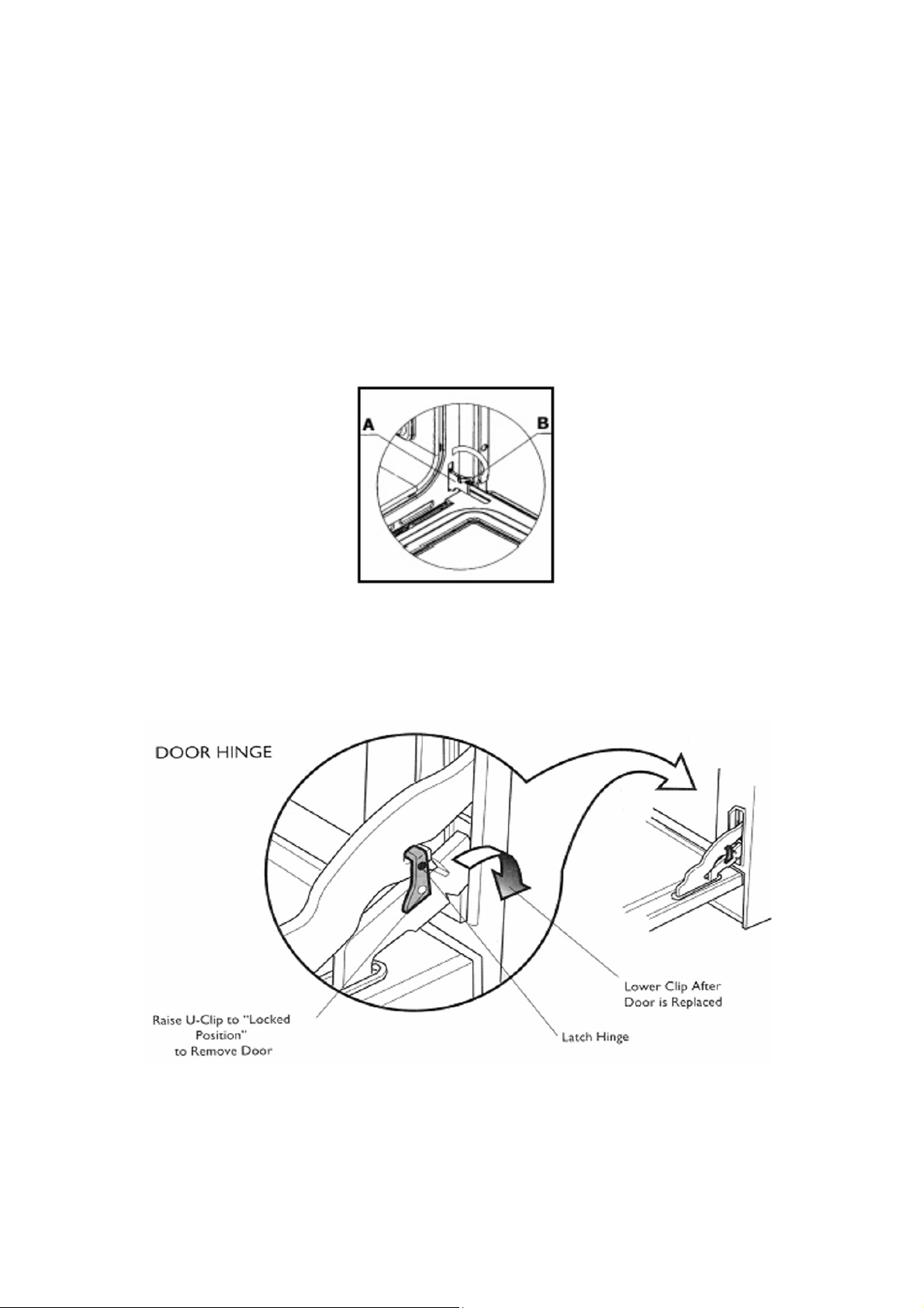
Fig. n° 11A
Fig. n° 11B
21 9880016900 E 05-2007 CE GAS OVEN
 Loading...