

Vitrek V4 Operating Manual
V4 Electrical Safety Analyzer
AC/DC/IR/GB
Operating Manual
Valid for all units S/N 14210 and up
99 Washington Street
Melrose, MA 02176
Fax 781-665-0780
TestEquipmentDepot.com
Advanced Test Equipment Rentals
www.atecorp.com 800-404-ATEC (2832)
®
E
s
t
a
b
l
i
s
h
e
d
1
9
8
1

Vitrek V4 – Electrical Safety Tester USER MANUAL
WA R N IN G
Vitrek Corporation, its representatives, vendors and distributors assume no liability for the operation of this
instrument in an unsafe manner. This instrument generates and delivers hazardous voltages (up to 5KVAC /
6KVDC). Always be extremely careful when using this instrument or any high voltage device. Read this
manual completely and observe operating precautions in section 3 before operating the instrument.
Limited Warranty
The standard warranty period for this instrument is one year from date of shipment. Please refer to your
invoice or shipping documents to determine appropriate warranty dates. Vitrek warrants to the original
purchaser that this product will be free from defects in material and workmanship under normal use
throughout the warranty period, provided that such defects are not determined by Vitrek to have been caused
by abuse, misuse, alteration, improper installation, neglect or adverse environmental conditions. Vitrek
Corporation's liability under this warranty is limited solely to the repair or replacement of this instrument
during the warranty period, provided it is returned to the factory freight prepaid with a return authorization
number.
No other warranty is expressed or implied. Vitrek Corporation is not liable for incidental, consequential,
direct or indirect damages nor for costs, losses or expenses of any kind. A return authorization number must
be obtained directly from the factory for warranty repairs. No liability will be accepted if returned without
factory authorization number.
Technical Support
After reading this manual, should you have any questions or need technical assistance – please contact Vitrek
customer support at:
Email: info@vitrek.com
Fax: (858)689-2760 9880A Via Pasar
Voice: (858)689-2755 San Diego, CA 92126 USA
Extended Three Year Warranty Program
To qualify your instrument for an extended three-year warranty period you must:
1. Register your unit within 30 days from receipt by faxing or emailing the following data
Vitrek Model no. & S/N
Contact Name
Company / Organization
Street Address
City, State, Zip Code
Contact Email Address
Contact Phone Number
2. Contact the factory for a reference number to return your unit to the factory for annual calibration and
re-certification prior to the expiration of the initial cal due date. Upon receipt of your PO for the
calibration fee, the warranty will be extended for an additional year (up to a maximum of three years
total warranty).
Vitrek Corporation
1

Vitrek V4 – Electrical Safety Tester USER MANUAL
TABLE OF CONTENTS PAGE
1. PRODUCT INTRODUCTION..........................…..
1-1. Description…………………………..………...
1-2. Feature………………………………….……...
2. SPECIFICATIONS………………………………... 7
5
5
6
3. PRECAUTIONS BEFORE OPERATION…….…
3-1. Unpacking the Instrument……..……………..
3-2. Safety Notice………………..………………….
3-3. Environment…………………………….…….
4. PANEL INTRODUCTION……………………..…
4-1. Front Panel…………………………………….
4-2. Rear Panel……………………………………..
10
10
10
11
11
11
12
5. OPERATING INSTRUCTIONS…..……………...
5-1. Main LCD Display..…………………………...
5-2. Preparing the EST for Use.…………………..
5-3. Structure of Stored Test Steps.……………….
5-4. Menu Parameter Setup & Operation………..
5-5. Remote Interface Operation.…………………
14
14
15
22
23
26
6. MAINTENANCE………..………………………… 27
7. PROGRAMMING…………………………………
7-1. Introduction…………………………………...
7-2. Connecting the V4 via the GPIB interface…..
7-3. Connecting the V4 via the RS232 interface….
7-4. Input and Output Queue……………………..
7-5. Commands and Syntax………………………..
7-6. Details of Command Reference………………
7-7. Status and Error Reporting…………………..
28
28
28
29
31
31
38
53
8. TROUBLE SHOOTING & MAINTENANCE..…
8-1. Fuse Rating and Type…………………………
8-2. Cleaning.………………………………...……..
8-3. Trouble Shooting.……..…………………...…..
8-4. V4 Calibration Procedure…………………….
58
58
58
58
59
2
Vitrek V4 – Electrical Safety Tester USER MANUAL
SAFETY TERMS AND SYMBOLS
These terms may appear in this manual or on the product:
WARNING. Warning statements identify conditions or practices that could result in injury or loss
of life.
CAUTION. Caution statements identify conditions or practices that could result in
damage to this product or other property.
The following symbols may appear in this manual or on the product:
DANGER A TTENTION Protective Ground
High Voltage Refer to Manual Conductor Terminal
Terminal
1. V4 PRODUCT INTRODUCTION
Our goal at Vitrek is 100% customer satisfaction with both our products and our people. Please fill free to
contact us if we can be of help with application or technical assistance, repair or calibration services
accessories or spare parts. Vitrek Corporation
9880A Via Pasar
San Diego, CA 92126 USA
Phone: (858)689-2755 Fax: (858)689-2760 E-mail: info@vitrek.com
1-1. Description
The Vitrek V4 Electrical Safety Testers comply with the requirement for electrical equipment &
appliance control ordinances as defined by UL, CSA, JIS, BS and many other international standards.
The tester is ideal for AC & DC voltage withstand (Hipot), insulation resistance measurement and
ground bond testing on a wide variety of electrical equipment and components.
1-2. Features
The Vitrek V4 offers several features:
1) No load setup of trip current and output voltage
A safe way to setup trip current and output voltage without high voltage activated.
2) A large 24×2 character LCD with adjustable LED backlight
Provide a clear display about test parameters, which including group, step, mode, status, output
voltage, trip current and test time.
3

Vitrek V4 – Electrical Safety Tester USER MANUAL
3) Easily and quickly setup by front panel
A user-friendly interface provides user an easy and quick way to set all parameters.
4) Electronic ramping and testing
Digital controlled ramping time and testing time.
5) Line and load regulation
Linear amplifier and feedback-control maintain output voltage disregard of the variation of load.
6) Selectable output frequency
50/60 Hz is selectable by utility setup.
7) Adjustable ARC detect level
ARC detects the level selectable by setup by utility setup.
8) 10 groups of storage and each group has 16 steps
Total 10 storage groups provided for testing of different products, and each group has 16 steps.
9) Adjustable output voltage during test
A special test mode on the COM group allows the user to adjust the output voltage during testing
10) Flashing high voltage indicator
A flashing red LED indicates dangerous situation during high voltage output is activated.
11) Data lock function
Front panel could be locked or unlocked by utility setup.
12) PLC remote control
The 9-pin interface provides inputs (START, RESET) and outputs (TEST, PASS, FAIL).
13) Compact size with multi-capability
The compact size is geared with the Safety Test capabilities including AC Withstanding test, DC
Withstanding test, Insulation Resistance test and Ground Bond test.
14) R/P Output
The output terminal is located on the rear panel.
15) Scanner Interface
A pair of Scanner test with 96 channels.
16) RS-232 and GPIB Interface
The RS-232 and GPIB interface enables remote control operation and signal processing via a PC.
Test Equipment Depot - 800.517.8431 - 99 Washington Street Melrose, MA 02176
FAX 781.665.0780 - TestEquipmentDepot.com
4
Vitrek V4 – Electrical Safety Tester USER MANUAL
2. VITREK V4 FOUR IN ONE SAFETY TESTER SPECIFICATIONS
1) AC Hi-Pot Specifications:
Voltage Range 0.100~5.000kV
Voltage Step 5V/step
Voltage Regulation
(line & load)
Voltage Accuracy 1% of reading +10V
Current Sourcing* 30~40mA(above 500V, maximum test time: 180 sec)
Current Limit 0.10~40mA, 0.02mA/step
Current Accuracy 1% of reading + 50μ A
2) DC Hi-Pot Specifications:
Voltage Range 0.100~6.000kV
Voltage Step 5V/step
Voltage Regulation
(line & load)
Voltage Accuracy 1% of reading +10V
Current Sourcing* 0.10~10.00mA(above 500V, continuous test)
Current Limit 0.10~10mA, 0.01mA/step
Current Accuracy 1% of reading + 50μ A
3) Insulation Resistance Specifications:
DC Voltage
Resistance Accuracy
4) Ground Bond Specifications
Test Voltage Max. 8V(DC)
Current Range 3~42A
Current Resolution 0.02A
Current Accuracy 1% of reading + 50mA
Resistance Range
Resistance Resolution
Resistance Accuracy
Test Method Four Te r m i n a l s Test Mode
1% + 5V
0.10~29.99mA(above 500V, continuous test)
0.10~10mA(below 500V, continuous test)
1% + 5V
0.10~2mA(below 500V, continuous test)
50V/100V/500V/1000V
50V/100V:
1~50MΩ : 5% of reading
51~200MΩ : 10% of reading
201~1990MΩ : 20% of reading
500V/1000V:
1~500MΩ : 5% of reading
501~2000MΩ : 10% of reading
2001~9999MΩ : 20% of reading
0~600mΩ
0.1mΩ
1% of reading +2mΩ
5) Ramp Time and Test Time
AC Hi-Pot Ramp/Test time 000.0~999.9s
DC Hi-Pot Ramp/Test time 000.0~999.9s
Insulation Resistance Time 001.0~999.9s
5
Vitrek V4 – Electrical Safety Tester USER MANUAL
Ground Bond Test Time 000.0~999.9s
6) ARC Detect
Detect Current 40 level (1~40mA)
7) Storage
Groups
Steps
8) Interface
RS-232 Standard
GPIB Option
9) PLC Control
D-sub 9 pins female Standard
10) Scanner Interface
D-sub 9 pins female Standard
11) Real Plate Output
Hi-pot terminals and GB
terminals
12) General
Power Source
Operation
Environment
Storage temperature
& Humidity
Accessories
Dimension 446(L) × 330(W) × 149(H) (m/m)
Weigh
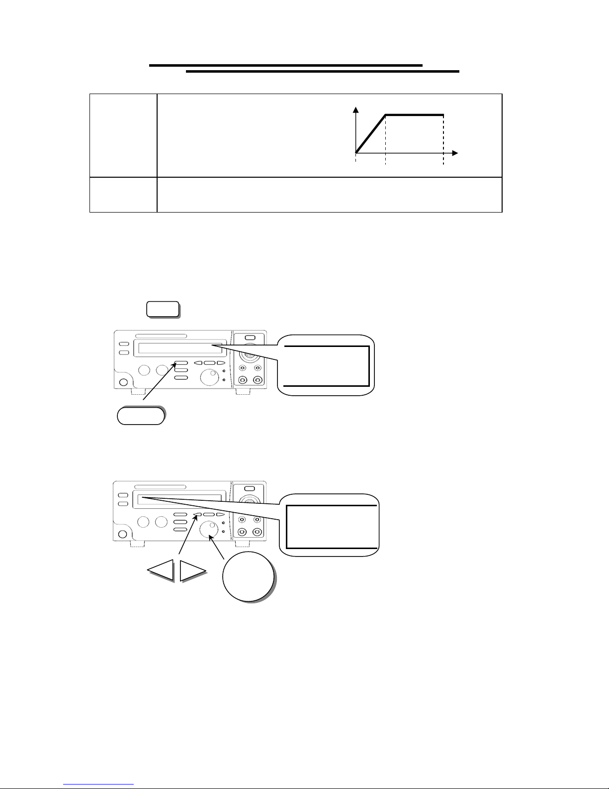
The main purpose provided by the series of instruments is for Puncture Testing. The specification is not for
continuous test. The temperature of heat sink is monitored. The test procedure will stop if the heat sink is too
hot. Please refer to Figure 2-1.
Stop the instrument for 10 minutes when continuously proceeding 30~40mA withstanding test for one hour.
GENERAL SPECIFICATIONS:
Test Database: 10 Test Sequences with up to 16 steps per test sequence
Front Panel Lockout: Prevents database edit while in lockout mode
Arc Detect: 10 level trip select
Remote Interface: Fully interactive RS232 standard, GPIB optional, standard 9-pin D-sub connector with
Outputs of Testing, Pass, Fail and inputs of Start, Reset. Output isolation is 400V with 130mA Continuous
load current.
Timer Accuracy: 0.10% ± 50mS
Power Source: AC100V, 120V, 220V, 230V (±10% 50/60Hz), 250W max
10
16
Standard interface for V4
AC100V, 120V, 220V, 230V±10% 50/60Hz
Indoor use, altitude up to 2000m.
Ambient Temperature 0℃ to 40℃.
Relative Humidity 80% (Maximum).
Installation category II
Pollution Degree 2
-10℃ to 70℃.
70% (Maximum).
TL-20-50 × 1, TL-463 × 1,
Instruction manual × 1,
Power Cord x 1
Approx. 14.9 kgs, 35lbs
6

Vitrek V4 – Electrical Safety Tester USER MANUAL
Operating Environment: Indoor use, Altitude up to 6500ft (2000m). Installation Category II. Pollution
Degree 2
Operating Temperature: 0°C to 40°C, 80% RH max.
Storage Temperature: -10°C to 70°C, 70% RH max
Dimension: 17.6”L x 13”W x 5.9”H, 446(L) x 330(W) x 149(H) mm
Weight: 30 lbs (14kg) net, 34 lbs (16 kg) ship
Accessories: NIST certification, TL-2050 Test Leads, Instruction Manual and power cord
Accuracy: Stated specifications apply for 1 year at 23 °C ± 5 °C
Calibration: Certificate of calibration, traceable to NIST provided
Compliance: CE mark certified to EN61010 and EMC directives EN50081-1 & EN50082-2
QuickTest™ Software Option QT-2: Bundled test automation software, with PC GPIB interface and cable.
It has an easy to load graphical test sequence development and operating environment. Provides time/date,
operator, test parameters, and test results for review, printout or export to database program.
mA
40
35
30
25
20
15
10
6
4
2
0
AC Hi-Pot
Spec 180sec
AC Hi-Pot Spec
Continuous
DC Hi-Pot Spec
Continuous
.1 .5 1kV 2 3 4 5 6 kV
Figure 2-1
7
Vitrek V4 – Electrical Safety Tester USER MANUAL
3. PRECAUTIONS BEFORE OPERATION
3-1. Unpacking the Instrument
The product has been fully inspected and tested before shipping from the factory. Upon receiving the
instrument, please unpack and inspect it for any damage that may have occurred during transportation. If
any sign of damage is found, notify the carrier and Vitrek or your distributor immediately.
3-2. Safety Notice
Work Place Safety
The work place must be isolated from routine traffic and when high voltage testing is in process, a
warning signal should be provided.
Checking the Line Voltage
The instrument can be connected to any kind of line voltage shown in the table below. Before connecting
the power plug to an AC line outlet, make sure the voltage selector on the rear panel is set to the correct
position corresponding to the line voltage. CAUTION: Damage to the instrument may occur if it is
connected to the wrong AC line voltage.
WARNING. To avoid electrical shock the power cord protective grounding conductor must be
connected to ground.
When line voltage is changed, install the required fuses shown as below:
Line voltage Range
100V
120V
WARNING. To avoid personal injury, disconnect the power cord before removing the fuse holder.
Operator’s Precaution
(1) Because of the extreme high output voltage and current of the breakdown tester, only a qualified person
should operate the tester in order to avoid fatal electric shock.
(2) On-the-job training is required for the operator to use the tester efficiently and safely.
(3) The operator should be prohibited from wearing metal jewelry, etc in order to avoid an electrical shock.
(4) A person with a heart condition or who wears a pacemaker must not operate the tester.
Safe, Secure Testing
The earth ground contact of the power cord must be properly connected in accordance with instructions.
The return lead must be connected to the tested object first before high voltage testing. Do not handle the
alligator test leads while high voltage is applied. Also, when using the optional HV probe do not touch the
exposed conductive tip of the test probe during testing. Provide full control the power supplied to the
tester by means of a carefully placed on/off switch or remote power control device.
WARNING: During testing, do not touch the test object or any other connected objects.
3-3.Environment
The normal ambient temperature range of this instrument is from 0° to 40°C (32° to 104°F). Operation of
the instrument above this specific temperature range may cause damage to the circuits.
90-110V
108-132V
Fuse Line voltage Range
T 7.0A
250V
220V
230V
198-242V
207-250V
Fuse
T 7.0A
250V
8
Vitrek V4 – Electrical Safety Tester USER MANUAL
Do not use the instrument in a place where a strong magnetic or electric field exists, as they may distort
the measurements.
4. PANEL INTRODUCTION
4-1. Front Panel
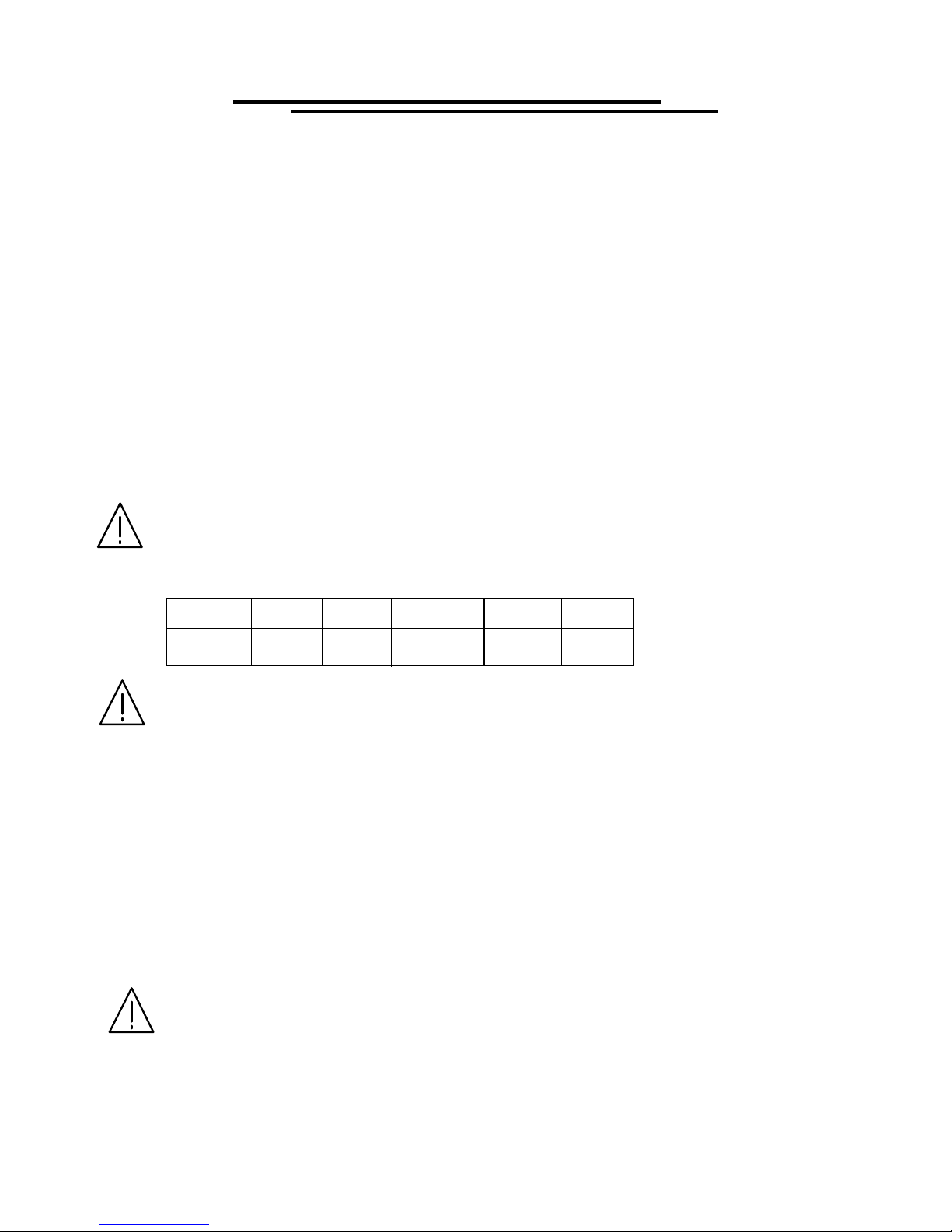
1 Model Number Model number and description
2 FAIL Indicator LED The red LED indicates failure of test procedure
3 PASS Indicator LED The green LED indicates pass of test procedure
4 CAUTION Indicator
LED
5 Main Display LCD The LCD displays all message about test procedure.
6 START Button Press the green button to start a test procedure.
7 RESET Button Press the red button to reset/stop a test procedure.
8 MENU Key
9 EDIT/SAVE Key
10 UTILITY Key
11 FIELD Key
12 Left Arrow Key Press the arrow key to adjust knob’s resolution.
13 Right Arrow Key Press the arrow key to adjust knob’s resolution.
14 Knob
15 LCD Backlight
Adjustment
16 Buzzer Volume
Adjustment
17 High Voltage Output
Seat
18 SOURCE-Terminal
(only for Ground
Bond Test)
19 SOURCE+ Terminal
(only for Ground
Bond Test)
20 Power Switch Press the power switch to turn on the tester.
21 SENSE+ Terminal Voltage Terminal for Ground Bond test.
During test the red LED will flash to indicate dangerous.
When you press the MENU key, the status becomes MENU and you can browse all
groups.
When you press the EDIT/SAVE key, the status EDIT is active and you can edit this
step or setup. Press the EDIT/SAVE key again will save this step or setup.
When you press the UTILITY key, the status UTILITY is active and you can view all
the utility setups.
When you edit the test step, press the FIELD key to change the active parameter of
stop.
If status EDIT is active, turn the knob to increase or decrease the value of active
parameter.
If status MENU is active, turn the knob to increase or decrease active Step.
Turn the VR to adjust the LED backlight of LCD.
Turn the VR to adjust the buzzer volume.
High voltage output terminal.
High current terminal for Ground Bond test.
High current terminal for Ground Bond test.
Test Equipment Depot - 800.517.8431 - 99 Washington Street Melrose, MA 02176
FAX 781.665.0780 - TestEquipmentDepot.com
9
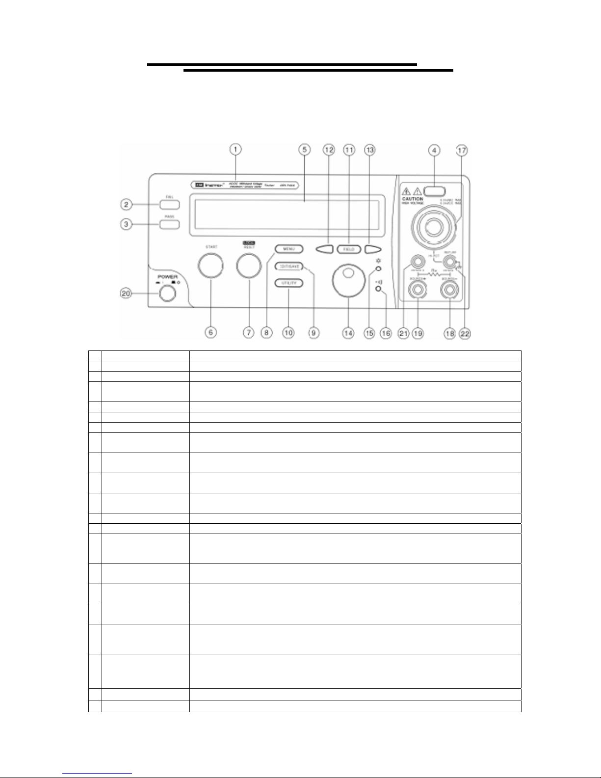
22 SENSE- & Return
Terminal
4-2. Rear Panel
Vitrek V4 – Electrical Safety Tester USER MANUAL
SENSE- Terminal is a voltage terminal for Ground Bond test, and Return Terminal is
for all test.
23 Ground Terminal Connect Ground terminal to the earth ground.
24 Fuse Holder with
Voltage Selector
25 AC Inlet Connect the AC power line to the inlet.
26 Remote Interface The remote interface performs all the functions of PLC control.
27 RS232 Terminal D-SUB 9 pin connector, Input/Output connector for RS232.
28 GPIB Terminal Blue 24 connector, Input/Output connector for IEE-488.
29 Scanner Interface D-sub 9 pins female connector for scanner box.
High Voltage Output
30
on rear panel
Sense + Terminal on
31
rear panel
Source + Terminal on
32
rear panel
Source - Terminal on
33
rear panel
Sense - Terminal &
34
Return Terminal on
rear panel
*The instrument can be used together with scanner box of SHB-001-1 & SHB-001-2.
To change AC source voltage, pull the fuse holder and rotate it to the proper value.
High voltage output terminal.
Voltage terminal for Ground Bond test.
High current terminal for Ground Bond test.
High current terminal for Ground Bond test.
Sense - terminal is a voltage terminal for Ground Bond test, Return terminal is for all
tests.
10
Vitrek V4 – Electrical Safety Tester USER MANUAL
5. OPERATION METHOD
5-1. Main Display LCD
Storage Mode Output Voltage/Current ARC Status
1 ~ 0 1 A C
I ma x = 0
Measurement Limit Ramp/Test Time
W V = 5
1 . 0 0 m
Table of Parameters:
Group/ Step: There are total 10 groups, and each group has 16 steps. The first number
Storage
Ex. 3:1Æ 3 is for group number, 1 is for step number.
The test mode of tester includes:
ACW: AC Withstanding voltage test.
DCW: DC Withstanding voltage test.
Mode
GB: Ground Bond test.
The total types of mode will change for different model.
Output voltage or current for each step
AC: Output voltage (0.100~ 5.000 kV)
Output
Voltage/Current
DC: Output voltage (0.100~ 6.000 kV)
GB: Output current (3.00~42.00A)
. 0 0 0 k V *READY
A T E S T:0 0 0 . 0 s
represents group while the second number represents step.
IR: Insulation Resistance.
IR: Output voltage (50V/100V/500V/1000V)
The status of tester includes:
MENU: Browse and check steps of test.
EDIT: Edit parameters
SAVE: Save parameters
Status
ARC
Measurement
Limit
UTIL: Browse and check system utility.
READY: Ready for test
TEST: Testing
PASS: The result of test is pass
FAIL: The result of test is fail
STOP: Stop the test
If the ARC function is enabled, the sign “*” means that there is ARC during test.
Lower and upper limit of measurement
Imax/Imin: Current measurement limit (ACW & DCW)
Rmax/Rmin: Resistance measurement limit(IR&GB&CNT)
11
Vitrek V4 – Electrical Safety Tester USER MANUAL
Ramp/Test
Time
CHANNEL
Hi: 00
Lo: 00
When the measured load becomes capacitive, the test time must be extended.
5-2. Prepare the EST for Use
Ramp time and test time
AC: Ramp/Test (000.0~999.9 s)
DC: Ramp/Test (000.0~999.9 s)
IR: Test (001.0~999.9 s)
GB: Test (000.0~999.9 s)
CNT: Test (000.0~999.9 s)
Any of the channels can be selected from the Scanner Box for output. If the selection
are Hi=01 and Lo=02 means channel 1 is high voltage output, and channel 2 is at
Return or Source terminal.
voltage
ramp
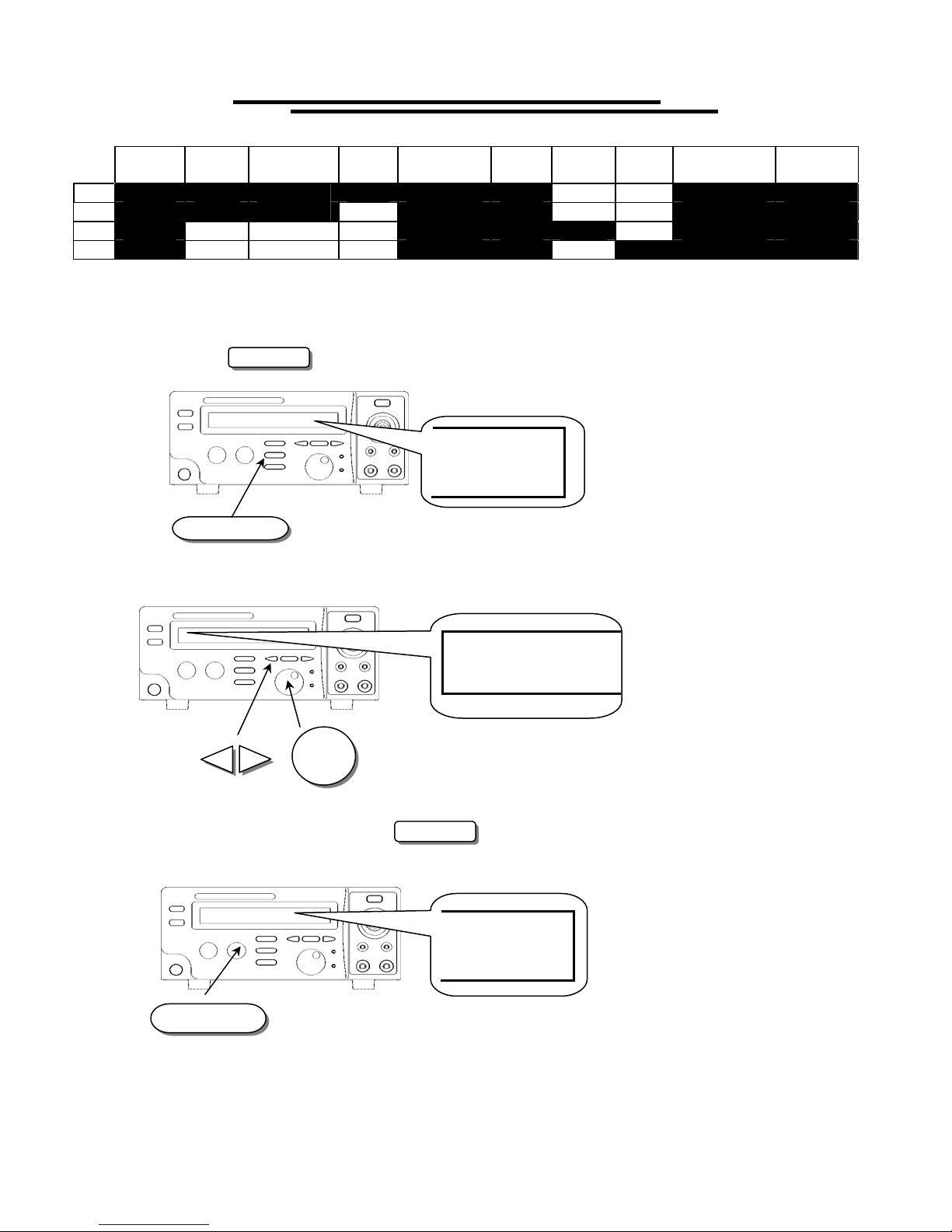
To view the Storage Steps
1. Press the MENU key to enter status MENU.
test
time
MENU
MENU
2. Use the left and right arrow keys to change knob’s resolution (group or step). Use the knob to change the
active step.
0-00 A C
12
Vitrek V4 – Electrical Safety Tester USER MANUAL
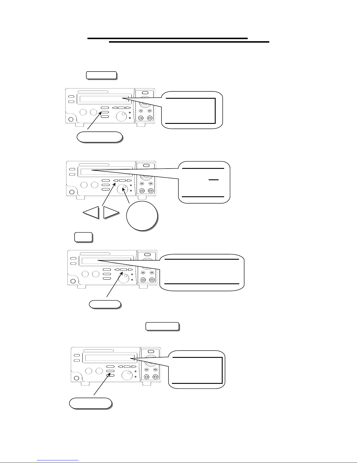
To Edit/Save the Storage Steps
1. Follow the above procedure “To View the Storage Steps “ to select a step.
2. Press the EDIT/SAVE key to enter status EDIT.
EDIT
EDIT/SAVE
3. Use knob to adjust parameter. Use arrow keys to change knob’s resolution.
AC W
4. Use FIELD key to change active parameter.
V=2
.00 0kV
5. Repeat step 3 and 4 to adjust parameter.
6. After setting all parameters, press EDIT/SAVE key to save the step. The status will become SAVE.
After the step is saved, the status will return to EDIT.
FIELD
SAVE
EDIT/SAVE
7. Repeat the procedure “To View the Storage Steps” to select another step.
13
Vitrek V4 – Electrical Safety Tester USER MANUAL
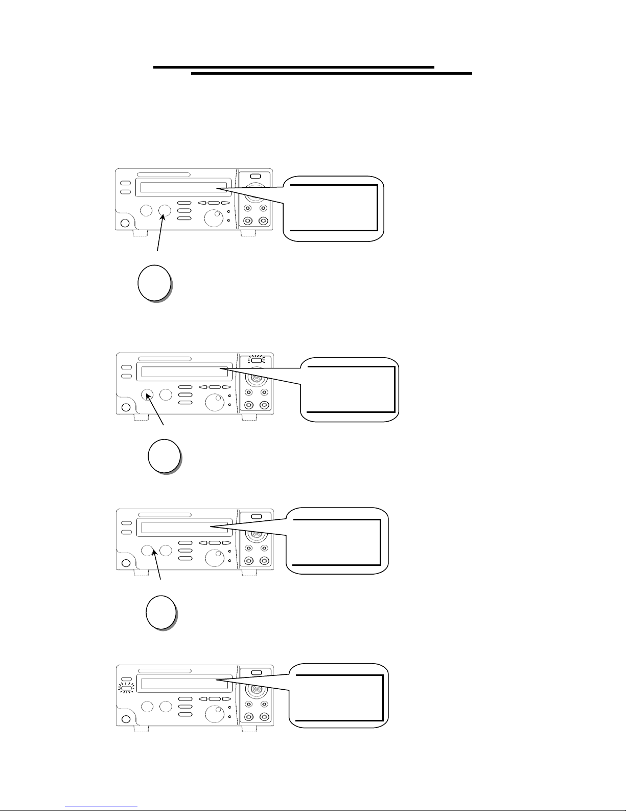
To Begin a Group Test
1. Repeat the procedure “To View the Storage Steps” to select a step.
2. Press RESET button to enter status READY.
READY
RESET
3. Make sure the test environment is safe.
4. Press START button to start the test while the status TEST is active and the CAUTION LED flashes.
5. If you press RESET button the test will stop immediately.
6. If the result is pass, the PASS LED will be active.
START
RESET
TEST
STOP
PASS
14
Vitrek V4 – Electrical Safety Tester USER MANUAL
7. If the result is fail, the FAIL LED will be active and the buzzer will alarm operator. To stop the alarm,
press RESET button again.
FAIL
RESET
8. Use knob to view the result of group step by step.
1-00
To View the System Utility
1. Press the UTILITY key to enter status UTIL.
UTIL
UTILITY
2. Use the knob or arrow keys to change the active parameter.
GRO UP TE ST
FRO M S TE P
15
1
Vitrek V4 – Electrical Safety Tester USER MANUAL
Table of System Utility:
Parameter Option Description
From STEP 1
GROUP TEST
ARC MODE*
From the
present step
DISABLE
ENABLE &
STOP
ENABLE &
CONTINUE
ARC CURRENT
AC FREQUENCY
TEST
CONTROL MODE
DATA LOCK
IR TEST MODE
ZERO CHECK
50 Hz
60 Hz
MODE 1
MODE 2
MODE 3
MODE 4
UNLOCKED
LOCKED
Stop on fail
Stop on pass
Timer
Zero check by shorting the resistance of test leads only for ground bond test.
(GB only)
RS-232 Baud
Interface
Rate
GPIB Address
Stop
FAIL Setting
Continue
*The arc detection circuit is tuned for high frequencies. It does not see any line frequency energy. Arcs are a
wide band phenomenon and are not required for electrical safety testing, so it is safe to disable this feature. It
is there primarily as a QC feature above and beyond the safety requirement. The safety spec is checking for
electrical breakdown of the primary insulation. Breakdown is defined by UL as a sudden and uncontrolled
flow of current. Since an arc tends to be a controlled flow of current it is not considered a breakdown.
Please note that the Utility menu is context sensitive—that is, the options available are contingent upon
which test is currently ready to be run. For example, if you have an ACW test ready, you will have the Arc
Mode and Current selections available to you, but not the IR Test Mode or GB Zero Check selections. To set
these, select either an IR or a GB test, respectively. The Group Test, Test Control Mode, Data Lock, Interface,
and Fail Setting options are available regardless of what test is selected. Refer to the following table for a
complete listing of options.
The group test procedure always begins from step 1 to end of group.
(e.g. 01~01)
The group test procedure always begins from the step selected to end
of group. (e.g. 01~03)
Disable the function arc detection.
Enable the arc detection and stop the test when arc is active.
Enable the arc detection and continue the test when arc is active.
Set the current level of arc detection.
Set the AC hi-pot output frequency to 50 Hz.
Set the AC hi-pot output frequency to 60 Hz.
Control mode of front panel.
Mode 1: Reset first (press reset button before test)
Mode 2: Press start button directly.
Mode 3: REMOTE I/O enable (the start button is disable)
Mode 4 : Reserved.
Accept and save all parameters of test step and utility.
Refuse to change any parameters of test step and utility.
Stop on fail at the DUT detection.
Stop on pass at the DUT detection.
Reach the time of determination for pass or fail.
1200, 2400, 4800, 9600.
00~31
The operation will stop upon the failure occurred at any step of group
test.
The operation will not stop until all 16 group steps have been tested.
16
Vitrek V4 – Electrical Safety Tester USER MANUAL
GROUP
TEST
AC
DC
IR
GB
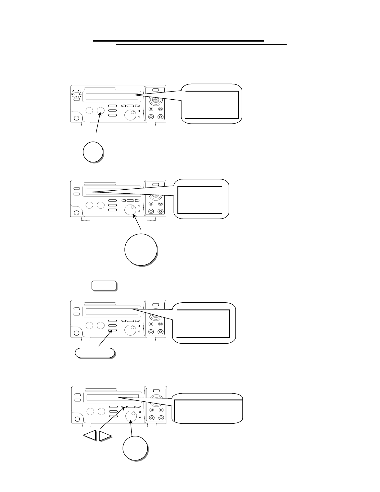
To Edit/Save the System Utility
ARC
MODE
1. Follow the above procedure “To View the System Utility” to select a parameter.
2. Press the EDIT/SAVE key to enter status EDIT.
ARC
CURRENT
AC
FREQ
TEST
CONTROL
DATA
LOCK
IR
MODE
GB
ZERO
INTERFACE FAIL
EDIT
EDIT/SAVE
3. Use knob to adjust parameter. Use arrow keys to change knob’s resolution.
SETTING
TE S T MO D
E
FR O M ST E P
4. After setting this parameter, press EDIT/SAVE key to save the parameter. The status will become
SAVE. After the parameter is saved, the status will return to EDIT.
SAVE
EDIT/SAVE
5. Repeat the procedure “To View the System Utility” to select another parameter.
17

Vitrek V4 – Electrical Safety Tester USER MANUAL
5-3. Structure of Storage Steps
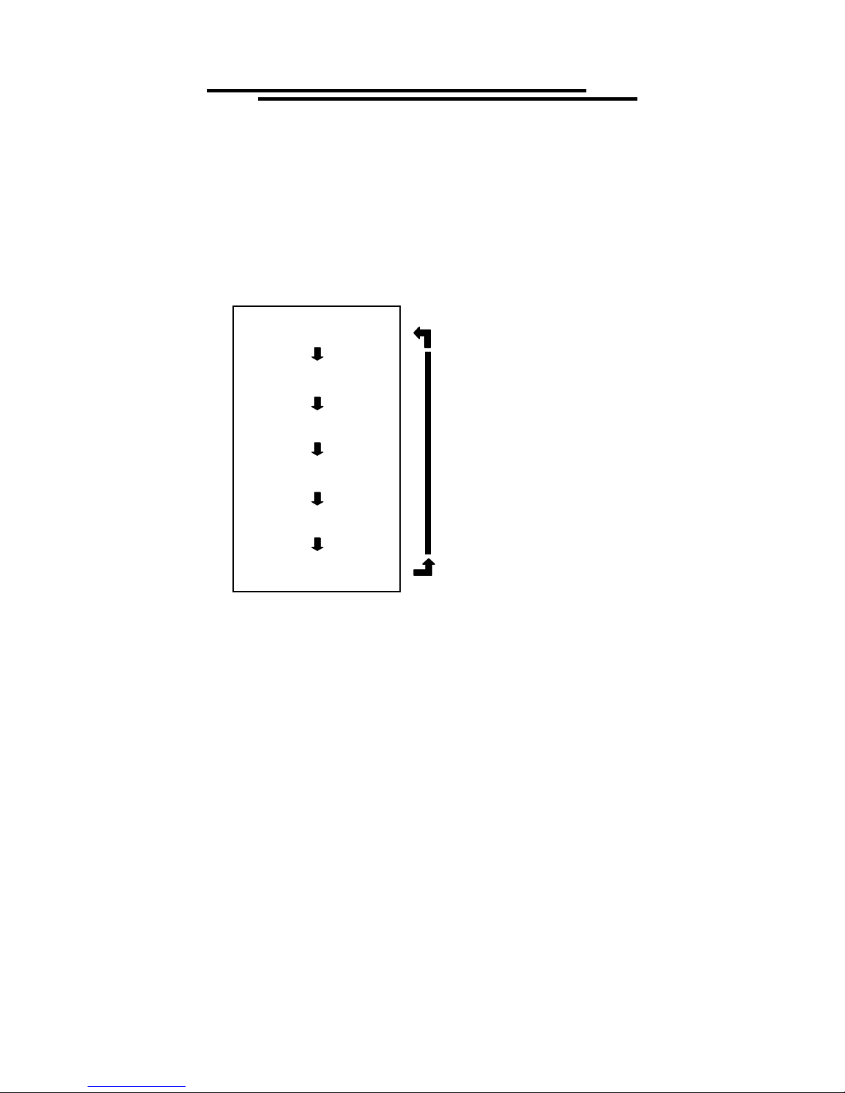
The storage steps of EST are total 10 groups (group 0 ~ group 9), 16 steps (step 1 ~ step 16) for each group.
Except these steps, there is another step “COM” for special test. The presentation of storage steps is Group:
Step. The first number represents group while the second represents step.
Group 0 Group 1 Group 2 Group 3 Group 4 Group
5
Step 1 0:1 1:1 2:1 3:1 4:1 5:1 9:1
↓
Step 2 0:2 1:2 2:2 3:2 4:2 5:2 9:2
↓
Step 3 0:3 1:3 2:3 3:3 4:3 5:3 9:3
↓
Step 4 0:4 1:4 2:4 3:4 4:4 5:4 9:4
↓
Step 5
∣
Step 16
0:5
0:16
↓
↓
↓
↓
1:5
1:16
↓
↓
↓
↓
2:5
2:16
↓
↓
↓
↓
3:5
3:16
↓
↓
↓
↓
4:5
4:16
↓
↓
↓
↓
5:5
5:16
The special test step “COM” contains another two types of test: CAC and CDC. The function of CAC (CDC)
is as same as ACW (DCW), except user could adjust the output voltage during test.
After each step has been tested, the tested status will be shown on the screen:
Step 1 2 3 4 5 6 7 8 9 0 1 2 3 4 5 6
Group
~
9:5
9:16
9
↓
↓
↓
↓
Test P P P P P P P P P P P P P P P P
N: Empty
P: Pass
F: Fail
Step 1: CH1
Step 2: CH2
Step 3: CH3
Step 4: CH4
Step 5: CH5
Step 6: CH6
Step 7: CH7
Step 8: CH8
Step 9: CH9
Step 0: CH10
Step 1: CH11
Step 2: CH12
Step 3: CH13
Step 4: CH15
Step 5: CH15
Step 6: CH16
18
Vitrek V4 – Electrical Safety Tester USER MANUAL
5-4. Menu Parameter Setup
z AC/DC Hipot – Voltage withstand test (ACW/DCW)
Press MENU key to enter MENU mode then use knob and arrow keys to select a step.
Press EDIT/SAVE key to enter EDIT mode. The cursor stays at the “test mode” field. Use knob to
select desired test ACW (DCW).
Functionality of FIELD key:
Measurement upper limit
Measurement lower limit
Press FIELD key to edit the next field “output voltage”. Use the knob to adjust the desired output
voltage while using the arrow keys to adjust the knob’s resolution (0.100~ 5.000 kV for ACW, 0.100~
6.000 kV for DCW).
Press FIELD key again to enter the next field “measurement upper limit”. Use the knob to adjust the
desired upper limit of leakage current while using the arrow keys to adjust the knob’s resolution
(0.10~15mA for ACW, 0.10~7.5mA for DCW).
Press FIELD key again to enter the next field “measurement lower limit”. Use the knob to adjust the
desired lower limit of leakage current while using the arrow keys to adjust the knob’s resolution
(0.10~15mA for ACW, 0.10~7.5mA for DCW).
Press FIELD key again to enter the next field “ramping time”. Use the knob to adjust the desired
ramping time while using the arrow keys to adjust the knob’s resolution (0~999.9s).
Press FIELD key again to enter the next field “testing time”. Use the knob to adjust the desired testing
time while using the arrow keys to adjust the knob’s resolution (0~999.9s).
Press FIELD key again to return to the first field “test mode” again.
Press EDIT/SAVE key to save all the parameters.
z Continuous AC/DC withstanding voltage test (CAC/CDC)
The CAC/CDC test is available only on “COM”. Like the traditional hipot tester, you can use the knob
and arrow keys to adjust output voltage during the test.
All the parameters of CAC/CDC are the same as ACW/DCW, except the testing time. The testing of
CAC/CDC is not limited.
Test mode
ACW (DCW)
Output voltage
V=X.XXXkV
Imax=XX.XxmA
Imin=XX.XxmA
Ramping time
RAMP=X.XXXs
Testing time
TEST=X.XXXs
19
Test Equipment Depot - 800.517.8431 - 99 Washington Street Melrose, MA 02176
FAX 781.665.0780 - TestEquipmentDepot.com
 Loading...