

Vitrek 95 Series, 951i, 952i, 953i, 954i Operating & Maintenance Manual
...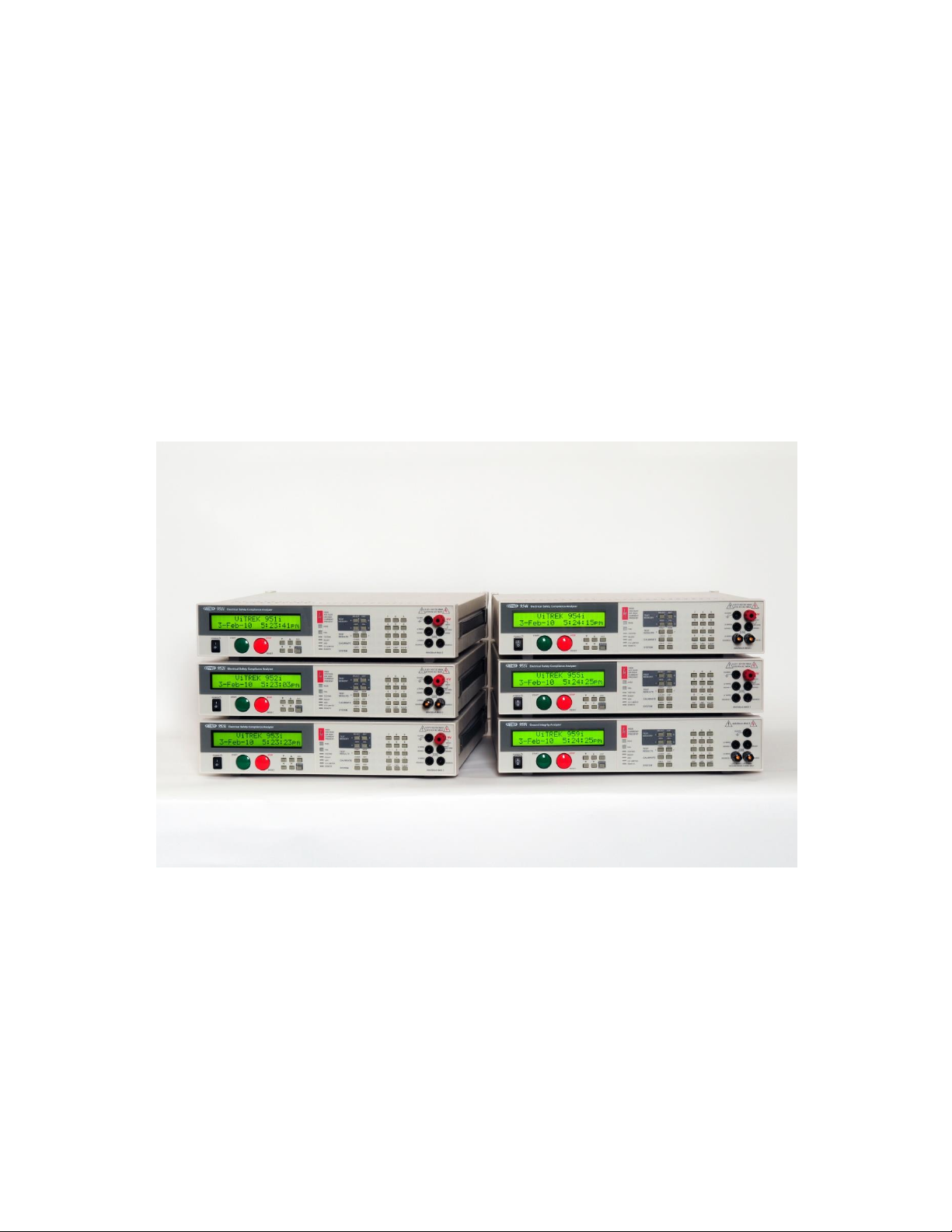
ViTREK
951 to 957i, and 959i
OPERATING & MAINTENANCE MANUAL

95x Series Operating Manual - June 27, 2016
About this Manual ......................................................................................................................................................... 9
Warranty Information ................................................................................................................................................. 10
SECTION 1 – PRODUCT INFORMATION........................................................................................................................ 11
Features ................................................................................................................................................................... 11
Available Models and Options ................................................................................................................................. 12
Interfacing Option................................................................................................................................................ 12
DC Voltage Options .............................................................................................................................................. 12
Internal AC Voltage Options ................................................................................................................................ 12
Internal GROUND BOND Option .......................................................................................................................... 13
External AC Voltage Option ................................................................................................................................. 13
Pulse Testing Option ............................................................................................................................................ 13
DUT Isolation Option ........................................................................................................................................... 13
Terminal Option ................................................................................................................................................... 13
Power Input Option ............................................................................................................................................. 13
Rack Mounting Option ......................................................................................................................................... 13
Output Voltage/Current Limiting Options ........................................................................................................... 13
SECTION 2 – SAFETY..................................................................................................................................................... 15
Power and Grounding .............................................................................................................................................. 15
Terminals and Wiring ............................................................................................................................................... 15
User Activated Safety Abort .................................................................................................................................... 16
Automatic Safety Abort ........................................................................................................................................... 16
SECTION 3 –INSTALLATION .......................................................................................................................................... 18
General Specifications ............................................................................................................................................. 18
Initial Inspection ...................................................................................................................................................... 18
Cooling ..................................................................................................................................................................... 18
Mounting Position and Orientation ......................................................................................................................... 19
Installing in a 19” Rack Enclosure ............................................................................................................................ 19
Line Power ............................................................................................................................................................... 19
Connecting Option AC-30 to the 95x ....................................................................................................................... 19
SECTION 4 – GENERAL FRONT PANEL OPERATION ...................................................................................................... 21
Front Panel .............................................................................................................................................................. 21
Menu Operation and Data Entry ............................................................................................................................. 23
Base Menu State .................................................................................................................................................. 23
Navigating Menus ................................................................................................................................................ 24
Page 2 of 154

95x Series Operating Manual - June 27, 2016
Modifying Menu Entries ...................................................................................................................................... 24
Adjusting the Display Contrast ................................................................................................................................ 26
Locking and Unlocking Menus ................................................................................................................................. 26
Unlocking Menus ................................................................................................................................................. 26
Setting, Changing or Clearing a Menu Lock Password ......................................................................................... 27
Relocking Menus.................................................................................................................................................. 27
Unknown Menu Lock Password........................................................................................................................... 28
Displaying Build Information ................................................................................................................................... 28
System Configuration Settings ................................................................................................................................. 29
Returning All Configuration Settings to Factory Defaults ........................................................................................ 30
SECTION 5 – TEST SEQUENCES .................................................................................................................................... 31
Test Sequence Configuration ................................................................................................................................... 32
Creating a New Test Sequence ................................................................................................................................ 33
Editing an Existing Test Sequence............................................................................................................................ 34
Deleting an Existing Test Sequence ......................................................................................................................... 35
Selecting and Running an Existing Test Sequence ................................................................................................... 35
Displayed Measurement Results ............................................................................................................................. 36
Reviewing Test Results after Running a Test Sequence .......................................................................................... 37
Printing a Test Results Report.................................................................................................................................. 39
Configuring the Test Results Report .................................................................................................................... 39
Manually Commanding a Test Results Report ..................................................................................................... 41
Compensating for External Lead Leakage and Impedance ...................................................................................... 41
SECTION 6 – TEST STEPS .............................................................................................................................................. 42
Choosing Within the Voltage Withstand and Leakage Testing Group ..................................................................... 42
Choosing AC, DC or PULSE Testing ....................................................................................................................... 43
Choosing the Limits ............................................................................................................................................. 43
AC Voltage Withstand and Leakage Testing (ACez, ACW and ACCAP) .................................................................... 46
Actions While Running ......................................................................................................................................... 47
Configuring .......................................................................................................................................................... 47
Connecting to the DUT ........................................................................................................................................ 50
Lead Compensation ............................................................................................................................................. 52
Examples .............................................................................................................................................................. 52
Specifications ....................................................................................................................................................... 53
DC Voltage Withstand and Leakage Testing (DCez, DCW and DCIR) ....................................................................... 56
Page 3 of 154

95x Series Operating Manual - June 27, 2016
Actions While Running ......................................................................................................................................... 57
Configuring .......................................................................................................................................................... 58
Connecting to the DUT ........................................................................................................................................ 62
Lead Compensation ............................................................................................................................................. 63
Examples .............................................................................................................................................................. 64
Specifications ....................................................................................................................................................... 66
Pulsed Voltage Withstand Testing (PULSE).............................................................................................................. 70
Actions While Running ......................................................................................................................................... 71
Configuring .......................................................................................................................................................... 71
Connecting to the DUT ........................................................................................................................................ 72
Lead Compensation ............................................................................................................................................. 72
Examples .............................................................................................................................................................. 73
Specifications ....................................................................................................................................................... 73
DC Breakdown Voltage Device Testing (BRKDN) ..................................................................................................... 74
Actions while Running ......................................................................................................................................... 74
Configuring .......................................................................................................................................................... 75
Connecting to the DUT ........................................................................................................................................ 75
Lead Compensation ............................................................................................................................................. 76
Examples .............................................................................................................................................................. 76
Specifications ....................................................................................................................................................... 77
Choosing Within the Resistance Testing Group ....................................................................................................... 77
DC Low Resistance Testing (LowΩ) .......................................................................................................................... 77
Actions while Running ......................................................................................................................................... 77
Configuring .......................................................................................................................................................... 78
Connecting to the DUT ........................................................................................................................................ 78
Lead Compensation (2-Wire) ............................................................................................................................... 79
Lead Compensation (4-Wire) ............................................................................................................................... 80
Examples .............................................................................................................................................................. 80
Specifications ....................................................................................................................................................... 80
AC Ground Bond Testing (GBez and GB) .................................................................................................................. 81
Actions While Running ......................................................................................................................................... 82
Configuring .......................................................................................................................................................... 82
Connecting to the DUT ........................................................................................................................................ 83
Lead Compensation ............................................................................................................................................. 85
Page 4 of 154

95x Series Operating Manual - June 27, 2016
Examples .............................................................................................................................................................. 85
Specifications ....................................................................................................................................................... 87
Ground Leakage Testing (DCI and ACI) .................................................................................................................... 88
Actions While Running ......................................................................................................................................... 88
Configuring .......................................................................................................................................................... 88
Connecting to the DUT ........................................................................................................................................ 89
Lead Compensation ............................................................................................................................................. 89
Examples .............................................................................................................................................................. 90
Specifications ....................................................................................................................................................... 91
Switch Unit Control (SWITCH) ................................................................................................................................. 92
Actions While Running ......................................................................................................................................... 92
Configuring .......................................................................................................................................................... 92
Examples .............................................................................................................................................................. 93
Specifications ....................................................................................................................................................... 93
Test Sequence Timing Control (PAUSE and HOLD) .................................................................................................. 93
Configuring .......................................................................................................................................................... 93
Examples .............................................................................................................................................................. 94
Specifications ....................................................................................................................................................... 94
SECTION 7 – CONNECTING AND CONFIGURING INTERFACES ..................................................................................... 95
LOCAL and REMOTE Operation ............................................................................................................................... 95
Controlling External Switch Matrix Units ................................................................................................................. 95
Configuration ....................................................................................................................................................... 95
Connections ......................................................................................................................................................... 97
Controlling the 95x by the RS232 Interface ............................................................................................................. 97
Specifications ....................................................................................................................................................... 97
Configuration ....................................................................................................................................................... 97
Connections ......................................................................................................................................................... 98
Controlling the 95x by the GPIB Interface ............................................................................................................... 98
Configuration ....................................................................................................................................................... 98
Connections ......................................................................................................................................................... 99
Controlling the 95x by the Ethernet Interface ......................................................................................................... 99
Specifications ....................................................................................................................................................... 99
Configuration ....................................................................................................................................................... 99
Connections ....................................................................................................................................................... 101
Page 5 of 154

95x Series Operating Manual - June 27, 2016
Printing from the 95x using the USB Interface ...................................................................................................... 101
Specifications ..................................................................................................................................................... 101
Connecting ......................................................................................................................................................... 101
Printing .............................................................................................................................................................. 102
SECTION 8 – DIO INTERFACE...................................................................................................................................... 103
Connector and Pinout ............................................................................................................................................ 103
Configuring ............................................................................................................................................................ 104
Signal Levels ........................................................................................................................................................... 105
Signal Isolation ....................................................................................................................................................... 106
Signal Timing .......................................................................................................................................................... 107
Starting with the START signal ........................................................................................................................... 107
Aborting with the ABORT or INTERLOCK signals................................................................................................ 107
PASS, FAIL and TESTING signals at the end of a Test Sequence ........................................................................ 107
HV PRESENT and DWELL Output Signals ........................................................................................................... 107
Examples ................................................................................................................................................................ 108
SECTION 9 – PERIODIC MAINTENANCE ..................................................................................................................... 110
Cleaning and Inspection ........................................................................................................................................ 110
Cable Inspection ................................................................................................................................................ 110
Fan Filter Cleaning ............................................................................................................................................. 110
Display Filter Cleaning ....................................................................................................................................... 110
Terminal Inspection ........................................................................................................................................... 111
Self Test ................................................................................................................................................................. 111
SECTION 10 – PERFORMANCE VERIFICATION AND ADJUSTMENT ............................................................................ 112
Adjustment Calibration .......................................................................................................................................... 112
Equipment Required .......................................................................................................................................... 113
Procedure .......................................................................................................................................................... 114
Verifying Calibration .............................................................................................................................................. 116
Equipment Required .......................................................................................................................................... 117
Starting Verification ........................................................................................................................................... 117
DC Voltage Verification ...................................................................................................................................... 118
DC Current Scaling Verification .......................................................................................................................... 118
DC Current Zero Verification ............................................................................................................................. 119
AC Voltage Verification ...................................................................................................................................... 119
AC Current Zero Verification .............................................................................................................................. 119
Page 6 of 154

95x Series Operating Manual - June 27, 2016
Low Ohms Resistance Verification..................................................................................................................... 120
Ground Bond Verification .................................................................................................................................. 120
Option HSS Current Verification ........................................................................................................................ 121
SECTION 11 – PROGRAMMING VIA AN INTERFACE ................................................................................................... 123
General Command Syntax ..................................................................................................................................... 123
Field Syntax ........................................................................................................................................................ 124
Field Separator................................................................................................................................................... 125
Command Separator .......................................................................................................................................... 125
Command Terminator ....................................................................................................................................... 125
General Response Syntax ...................................................................................................................................... 125
Delays and Timeouts.............................................................................................................................................. 126
Multiple Interface Operation ................................................................................................................................. 126
Front Panel Operation While Using Interfaces ...................................................................................................... 126
GPIB Bus Commands.............................................................................................................................................. 127
Device Clear (SDC and DCL) ............................................................................................................................... 127
Interface Clear (IFC) ........................................................................................................................................... 127
Group Execute Trigger (GET) ............................................................................................................................. 127
Ethernet Sessions .................................................................................................................................................. 127
Status Registers ..................................................................................................................................................... 128
STB and SRE Registers ........................................................................................................................................ 128
OPC Register ...................................................................................................................................................... 128
ESR Register ....................................................................................................................................................... 129
ERR Register ....................................................................................................................................................... 129
Commands ............................................................................................................................................................. 130
*IDN? Response Fields ....................................................................................................................................... 134
ACez Configuration Fields .................................................................................................................................. 134
ACW Configuration Fields .................................................................................................................................. 135
DCez Configuration Fields .................................................................................................................................. 136
DCW Configuration Fields .................................................................................................................................. 137
DCIR Configuration Fields .................................................................................................................................. 138
GBez Configuration Fields .................................................................................................................................. 139
GB Configuration Fields ..................................................................................................................................... 139
LowΩ Configuration Fields ................................................................................................................................. 140
ACCAP Configuration Fields ............................................................................................................................... 141
Page 7 of 154

95x Series Operating Manual - June 27, 2016
ACI Configuration Fields .................................................................................................................................... 142
DCI Configuration Fields .................................................................................................................................... 142
PULSE Configuration Fields ................................................................................................................................ 143
BRKDN Configuration Fields .............................................................................................................................. 144
PAUSE Configuration Fields ............................................................................................................................... 144
HOLD Configuration Fields ................................................................................................................................. 145
SWITCH (948i configuration) Configuration Fields ............................................................................................ 145
SWITCH (964i configuration) Configuration Fields ............................................................................................ 145
Test Step Status Flags ........................................................................................................................................ 146
STEPRSLT? Response Fields ............................................................................................................................... 147
Programming Example........................................................................................................................................... 148
Programming Guidelines ....................................................................................................................................... 148
Migrating from Earlier Firmware Versions ................................................................................................................ 152
Page 8 of 154

95x Series Operating Manual - June 27, 2016
ABOUT THIS MAN UAL
Throughout this document the instrument is referred to as the 95x, this applies to all instruments in the 95x series
having a main firmware revision of 2.30, there may be differences if the 95x being operated has a different main
firmware version. At the end of this manual is a section detailing the differences between v2.30 and earlier
versions of the firmware (see Migrating from Earlier Firmware Versions).
Due to continuing product refinement and possible manufacturer changes to components used in this product,
ViTREK reserves the right to change any or all specifications without notice.
This manual has been created with “clickable” links. Where a reference is made to another section of the manual,
the user may click on the section name reference and the document will automatically go to that section.
The table of contents is “clickable”. The user may click on any of the entries to go to that section.
The table of contents is also made available as Bookmarks for Adobe Reader or Acrobat, allowing the user to
permanently display the table of contents alongside the document and navigate by clicking on each section as
needed.
Page 9 of 154

95x Series Operating Manual - June 27, 2016
WA RRAN TY I NFORMAT ION
This ViTREK instrument is warranted against defects in material and workmanship for a period of 1 year after the
date of purchase (extended up to a total of 3 years with registration and annual calibrations at ViTREK). ViTREK
agrees to repair or replace any assembly or component (except batteries) found to be defective, under normal use,
during the warranty period. ViTREKs obligation under this warranty is limited solely to repairing any such
instrument, which in ViTREKs sole opinion proves to be defective within the scope of the warranty, when returned
to the factory or to an authorized service center. Transportation to the factory or service center is to be prepaid by
the purchaser. Shipment should not be made without prior authorization by ViTREK.
This warranty does not apply to any products repaired or altered by persons not authorized by ViTREK or not in
accordance with instructions provided by ViTREK. If the instrument is defective as a result of misuse, improper
repair, improper shipment, or abnormal conditions or operations, repairs will be billed at cost.
ViTREK assumes no responsibility for its products being used in a hazardous or dangerous manner, either alone or
in conjunction with other equipment. Special disclaimers apply to this instrument. ViTREK assumes no liability for
secondary charges or consequential damages, and, in any event, ViTREKs liability for breach of warranty under any
contract or otherwise, shall not exceed the original purchase price of the specific instrument shipped and against
which a claim is made.
Any recommendations made by ViTREK or its representatives, for uses of its products are based on tests believed
to be reliable, but ViTREK makes no warranties of the results to be obtained. This warranty is in lieu of all other
warranties, expressed or implied and no representative or person is authorized to represent or assume for ViTREK
any liability in connection with the sale of our products other than set forth herein.
Document number MO-95x-GOM revision H, 26 June 2016.
Copyright© 2009-2015 ViTREK.
All rights reserved. No part of this publication may be reproduced, transmitted, transcribed, stored in a retrieval
system, or translated into any language in any form without prior written consent from ViTREK. This document is
copyrighted and contains proprietary information, which is subject to change without notice. The product displays
and instructional text may be used or copied only in accordance with the terms of the license agreement.
In the interest of continued product development, ViTREK reserves the right to make changes in this document
and the product it describes at any time, without notice or obligation.
ViTREK
12169 Kirkham Road,
Poway, CA 92064 USA
Telephone: 858-689-2755
Fax : 858-689-2760
Web : www.vitrek.com
Email : info@vitrek.com
Page 10 of 154

95x Series Operating Manual - June 27, 2016
SECTION 1 – PRODUCT INFORMATION
FEATUR ES
The 95x is an advanced Electrical Safety Analyzer with many standard features which make it unique in this field.
Multiple Capabilities. The 95x is capable of a very wide range of safety tests and is also capable of making
specialty measurements on components – all in the same instrument.
Multiple Safety features. The 95x has many built-in safety features, such as ground current detection,
DUT safety ground disconnection detection, and more. The standard digital interface allows the user to
use safety interlocks and remote safety indicators with ease.
No regrets. With all of the features shown here, the 95x is capable of so much more than the typical
users’ present requirements, the user will not regret choosing the 95x when new more stringent
requirements come up in the future.
Wide range of voltages and currents generated. The 95x has a test voltage range from a few 10’s of volts
to several 10’s of kilovolts (for withstand testing) and a test current range from a few microamps to 10’s
of amps (for chassis ground bond testing) at DC or over a frequency range from 20 to 500Hz. The 95x is
not limited to just a few voltages, currents or frequencies, the user can specify the actual level and
frequency they desire. The 95x is not weak either – loads up to 500VA can be accommodated.
Wide range of voltages and currents measured. The 95x does not just have a wide range of generated
voltages and currents – it can measure them too. From microvolts to 10’s of kilovolts, and from 100’s of
picoamps to 100’s of milliamps are all measured by the 95x. Using its’ DSP based technology the 95x
knows the difference between breakdown currents, leakage currents and arcing currents and gives you all
of the results.
Advanced measurements. When it comes to AC measurements the 95x does not just measure the basics -
the 95x measures total, in phase and quadrature components all of the time and makes available more
advanced results such as in phase resistance, quadrature reactance, capacitance and dissipation factors.
Result Analysis. The 95x does not just measure, it analyses the measurements – after a test has been run
the minimum, maximum, average and final measurements are available, a running total of the passes and
failures for each test step are also maintained across multiple runs.
Not just “does not breakdown” but “does breakdown” too. The 95x is not only capable of testing that a
DUT does not breakdown, but it is also capable of testing that a surge suppressor type device does
breakdown at the correct voltage. Ever worried if that surge suppressor you disconnected while safety
testing was correctly reconnected, does it work, is it in specification? Not a problem for the 95x – it can
be tested after safety testing.
The 95x adapts itself to the load automatically. The 95x does not have the load restrictions so often found
(and so often hidden in the small print) in other safety analyzers – load capacitances up to a farad during
DC withstand testing, highly inductive loads when low resistance testing, and more, are automatically
accommodated by the 95x adapting itself to the actual load during each test. Measurements on DUTs like
solar panels and computer system line filters are made by the 95x with ease.
Stand alone operation. The 95x can be programmed by the user to perform up to 254 test steps in a
sequence. Each step is automatically performed by the 95x either with or without user intervention as
the user desires. Up to 100 such sequences can be defined and maintained in the instrument, no
Page 11 of 154
95x Series Operating Manual - June 27, 2016
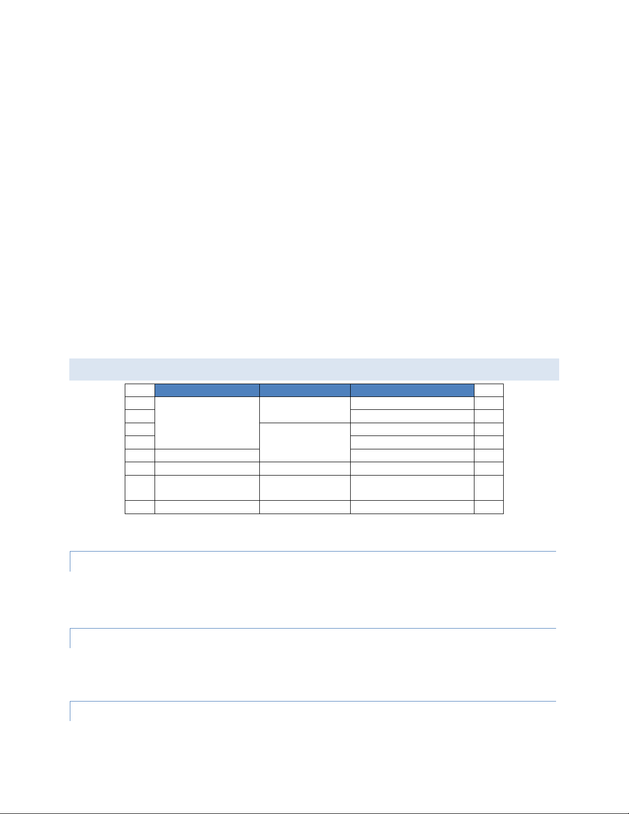
AC Voltage Testing
DC Voltage Testing
AC Low Resistance Testing
951i
20-6000V
20-6500V
No
951i
952i
0.1-40A @ 8V
952i
953i
40-11000V
No
953i
954i
0.1-40A @ 8V
954i
955i
40-10000V
No
955i
956i
No
20-6500V
No
956i
957i
20-6000V
(40-10000V Opt AC10)
75-15000V
No
(0.1-40A Opt GB40)
957i
959i
No
No
0.1-40A @ 8V
959i
computer is required. The 95x is capable of controlling switch matrix units (also available from ViTREK) –
up to 256 channels can be controlled without needing a computer or software. The 95x can even print a
test report on a printer for you when a test sequence has completed.
System operation - Wide range of interfaces available. If the user wishes to use the 95x with a computer,
then RS232, GPIB or Ethernet interfacing can be chosen as the interfacing medium between them. Giving
the user the flexibility to use the 95x in almost any computing environment. Software (QuickTest Pro) is
available from ViTREK to provide all the control needed for any system from the simple (just the 95x) to
the most complex with the 95x terminals being multiplexed between DUTs and/or points within DUTs by
up to 1024 channels in switch matrix units (also available from ViTREK).
High Speed. The 95x is capable of performing very quickly, up to 100 tests per second can be performed
with the test results being made available both during each test and after the entire sequence has been
run. The 95x is also capable of chaining similar tests without needing to reduce the applied voltage or
current to zero between test steps, this considerably speeds up testing when multiple test levels are
required.
All of the measurements, all of the time. The 95x does not just measure what the user has set limits for,
all measurement results for the specific type of test being performed are made available to the user.
Energy Efficient. The 95x uses direct line switching power supplies to provide a very energy efficient
instrument, the 95x only draws significant power from the line when needed to power the load.
AVAILABLE MODELS AND O PTIONS
In addition to the above, all models have 2- and 4-wire DC Low Resistance and Ground Leakage Testing capabilities,
a RS232 interface, a Digital I/O interface and a VICL proprietary interface.
INT ERFA C ING OPTI ON
This option may be fitted in any 95x.
Option GPIB-9 adds a GPIB interface.
The 95x has Digital I/O, RS232, Ethernet and USB Printer interfaces as standard.
DC VOLT A GE O PTIO N S
This option may be fitted in any 95x except the 959i.
Option DCNEG changes the polarity of the DC Voltage capability to negative, but limits the minimum DC output
voltage to 200V.
INT ERNA L AC VOLTA GE O PTIO NS
One or none of these options may be fitted in a 951i, 952i, 953i, 954i or 957i.
Page 12 of 154

95x Series Operating Manual - June 27, 2016
Option AC-2 changes the AC Voltage capability to 10-2000V, and has increased drive capability at all voltage output
levels.
Option 500VA (not available for the 952i or 954i) extends the AC voltage drive capability to 100mArms.
Option AC-10 (only available for the 957i) extends the AC voltage drive capability to 10KVrms (same as standard in
a 955i).
INT ERNA L GR O UND BOND OPTION
This option may be fitted in a 957i and cannot be fitted if Opt. AC-10 is fitted.
Option GB-40 adds ground bond testing capability to the 957i (same as standard in a 952i, 954i and 959i).
EXT ERNA L AC VOLT AGE OPTI O N
This option may be fitted in a 951i, 952i, 953i, 954i, 955i or 957i.
Option AC-30 extends the maximum AC Voltage capability to 30KV by means of an external unit.
PUL SE T ESTI N G OP TION
This option may be fitted in a 951i, 952i, 953i or 954i (not available with Option 500VA) or a 957i (not available
with Opt. AC-10).
Option PMT-1 adds pulsed voltage testing.
DUT ISO L ATI O N OPT ION
One of these options may be fitted in a 951i, 952i or 956i.
Option HSS adds the ability to measure AC or DC breakdown and/or leakage into a grounded DUT with down to
10nA resolution.
Option HSS-2 adds the ability to measure DC breakdown and/or leakage into a grounded DUT with down to 1nA
resolution.
TE R MINA L OPT ION
One or none of these options may be fitted in any 95x.
Option RPO-95 adds rear panel terminals in parallel with the front panel terminals.
Option RPOO-95 replaces the front panel terminals with rear panel terminals.
POW ER I NPUT OPTI ON
Any of these options may be fitted in any 95x.
Option LOLINE changes the standard 105-245Vrms line voltage range to 80-125Vrms.
Option INRUSH reduces the power-on inrush current at 230V line from over 100Apk to nominally 40Apk but limits
the line voltage range to 200-245Vrms.
RAC K MO UNTI N G OP TION
This option may be fitted in any 95x.
Option RM-1 allows for standard 19” rack mounting of the 95x.
OUT PUT V OLTA GE/CURR E NT L IMITING OPTI O NS
The user may, at the time of order, specify that the DC and/or AC Voltage generated by the 95x may be limited to a
user specified voltage less than that normally available from the specific unit model (but must be greater than
Page 13 of 154

95x Series Operating Manual - June 27, 2016
100V). Similarly, the user may specify that the Ground Bond current generated by a 952i, 954i or 959i is limited to
a user specified current between 1 and 40Arms. The remainder of this manual assumes that these optional limits
are at the maximum for the specific model.
SOF TWAR E
QT Pro II – 950. A 45 day free trial included with each unit. This software provides-
The user does not need to write software to use the 95x with a computer.
Can control testing using very complex switching systems when used with ViTREK 964 Switch Matrix units.
Easy to use fully graphical interface on a Windows based computer.
Multi-level user login, enabling the configuration of tests to be locked except for certain users.
Company wide use of test sequences using the company network.
Test sequences can be downloaded into the 95x and run without the computer.
Test results recorded on a computer or on the company network.
Computer generated multi-level test reports.
Compatibility with a wide range of Windows versions (Windows XP through Windows 8 as a Desktop
Application).
ACC ESSO RIES
TL-115-95. 115V Receptacle Hipot Test Adaptor
TL-115-GBR. 115V Receptacle Ground Bond Test Adaptor
TL-115-95GBR. 115V Receptacle Hipot and Ground Bond Test Adaptor
TL-IEC-95. IEC320 Power Socket Lead set for HiPot
TL-IEC-GBR. IEC320 Power Socket Lead set for Ground Bond
TL-IEC-95GBR. IEC320 Power Socket Lead set for HiPot and Ground Bond
TL-209. Standard HV/CONT Alligator Clip Test Lead Set (one supplied with each unit).
K-1R. 4-Wire Kelvin Low Resistance Measurement Lead Set
K-2R. 4-Wire 40A GB Test Lead Set (one supplied with each 952i, 954i, 959i, and 957i with Opt GB40).
RS-2. 6ft RS232 null-modem cable (95x to Computer).
RSS-9. Remote Start Switch.
RSF-9. Remote Start Footswitch.
HVW-9. High Voltage Warning Light.
RM-1. Rack Mount Kit for the 95x series.
DIO-IS9. DIO Isolator for the 95x series. Available in models for 3V, 5V, 12V, or 24V logic.
Page 14 of 154

95x Series Operating Manual - June 27, 2016
SECTION 2 – SAFETY
The user should be aware of these safety warnings at all times while using the 95x.
WARNING - THE 95x PRODUCES VOLTAGES AND CURRENTS WHICH MAY BE LETHAL, UNSAFE
OPERATION MAY RESULT IN SEVERE INJURY OR DEATH.
WARNING - IF THE 95x IS USED IN A MANNER NOT SPECIFIED BY VITREK, THE PROTECTION PROVIDED BY
THE EQUIPMENT MAY BE IMPAIRED AND SAFETY MAY BE COMPROMISED.
POWER AND GROUNDING
WARNING - THE 95x IS INTENDED TO BE POWERED FROM A POWER CORD HAVING A PROTECTIVE
GROUND WIRE WHICH MUST BE INSERTED INTO A POWER OUTLET HAVING A PROTECTIVE GROUND
TERMINAL. IF THE 95x IS NOT POWERED FROM A SUITABLE POWER SOURCE THEN THE CHASSIS
GROUND TERMINAL LOCATED NEAR THE POWER ENTRY CONNECTOR ON THE REAR PANEL MUST BE
PROTECTIVE GROUNDED.
WARNING - TURNING OFF OR OTHERWISE REMOVING POWER TO THE 95x WHILE IT IS GENERATING
HIGH VOLTAGES WILL NOT ENABLE THE 95x TO DISCHARGE THE DUT AND MAY DAMAGE THE 95x. THE
DUT MAY HAVE DANGEROUS VOLTAGES PRESENT FOR LONG PERIODS OF TIME AFTER THIS OCCURS.
WARNING - DO NOT REMOVE THE POWER CORD FROM THE 95x OR FROM THE SOURCE OF POWER
WHILE IT IS OPERATING AT HIGH VOLTAGES. THIS WILL REMOVE THE PROTECTIVE GROUND FROM THE
CHASSIS OF THE 95x AND THE DUT WHICH MAY RESULT IN HAZARDOUS VOLTAGES BEING ACCESSIBLE
TO THE USER.
TERMINALS AND WIRING
WARNING - THE 95x PRODUCES VOLTAGES AND CURRENTS WHICH MAY BE LETHAL, ENSURE NO
VOLTAGE OR CURRENT IS PRESENT WHEN CONNECTING TO OR DISCONNECTING FROM THE TERMINALS
OR DUT.
The HIGH VOLTAGE OR HIGH CURRENT PRESENT warning symbol on the front panel of the 95x is illuminated
whenever an unsafe voltage is present on the HV terminal or a high current is present between the SOURCE
terminals.
WARNING - THE 95x PRODUCES VOLTAGES OF UP TO 10kVrms ON THE HV TERMINAL(S). THE USER
MUST ENSURE THAT CONNECTIONS TO THESE TERMINALS HAVE SUFFICIENT INSULATION FOR THESE
VOLTAGES. EVEN WHEN SUFFICIENT INSULATION IS PRESENT, THE USER SHOULD NOT PUT ANY PART OF
THEIR BODY IN CLOSE PROXIMITY TO THE CONNECTIONS WHILE HIGH VOLTAGES ARE PRESENT.
The insulation of the wiring to the HV terminal of the 95x must be rated for at least the highest voltage expected
during the test sequence.
The user should ensure that all personnel remain at a safe distance from the HV wiring during testing.
Page 15 of 154

95x Series Operating Manual - June 27, 2016
When using high voltages, even if there is sufficient insulation, there may be significant capacitive coupling which
can cause an unsafe current to flow to nearby objects and corona can occur even outside of the insulation. This is
made worse by sharp corners on objects or the wiring. In severe cases corona can cause interference with the
measurements of the 95x and will reduce the capabilities of the wiring insulation over time, eventually resulting in
insulation failure.
When using extremely high voltages, especially when using Opt. AC-30, there may be significant mechanical force
between the HV wiring and nearby objects. Loose wiring can move several inches, and nearby loose objects (e.g.
screws or papers) can be attracted to the high voltage wire.
All terminals of the 95x other than the HV terminal are always protected to be within a safe voltage of the 95x
chassis ground, so high voltage wire is generally unnecessary for connections to them.
Should the DUT exhibit significant breakdown or arcing while being tested, there may be very high energy HF
interference generated. Although this only lasts for a small period of time before the 95x shuts down, in severe
cases this can damage nearby equipment, such as computers. The wiring between the 95x terminals and the DUT
should be routed as far as possible away from other equipment and from all cabling connected to other
equipment.
When charging high capacitance loads to high DC voltages the capacitor may be unsafe if it or the wiring to it
exhibits breakdown while being tested. The energy in the breakdown is generated by the capacitor itself, so there
can be no limit on this energy imposed by the 95x.
WARNING - SOME 95x MODELS PRODUCES CURRENTS OF UP TO 40Arms ON THE SOURCE + AND TERMINALS. THE USER MUST ENSURE THAT CONNECTIONS TO THESE TERMINALS HAVE A SUFFICIENT
CURRENT CARRYING RATING.
The current rating of all wiring must be sufficient for at least the highest current expected from that terminal
during the test sequence.
Generally all wiring should be rated for at least 100mA, but the SOURCE+ and SOURCE- terminal wiring for a 952i,
954i or 959i performing Ground Bond testing should be rated for the highest set test current (this may be up to
40A).
USER A CTIV ATED SAFETY ABOR T
The user may depress the STOP button on the 95x front panel at any time while a test sequence is being
run to remove the voltage or current as quickly as possible and abort the test sequence.
The user can configure for a digital INTERLOCK signal to be input to the DIO Interface which will abort a
high voltage or current test step if the interlock is opened. See SECTION 8 – DIO INTERFACE.
The user can configure for a digital ABORT signal to be input to the DIO Interface which will abort any type
of test step if asserted. See
Page 16 of 154

95x Series Operating Manual - June 27, 2016
SECTION 8 – DIO INTERFACE.
There are several interface commands which can be used to abort a running test sequence. See SECTION
11 – PROGRAMMING VIA AN INTERFACE.
AUTOMA TIC SAFETY ABORT
For AC or DC voltage test steps, if the breakdown current level is set to <7mApk and the HI SAFETY setting
in the CNFG - TEST menu is enabled, the 95x will fail the test if excessive HV terminal current is detected.
This effectively reduces the drive capability of the 95x to a safer level of current (nominally 7.5mA peak)
during these test steps. See Test Sequence Configuration.
For AC or DC voltage test steps, the RETURN terminal of the 95x provides a protective ground to the DUT.
The user may wish to take precautions to ensure its’ connection to the DUT. If the CONTINUITY SENSE
setting in the CNFG - TEST menu is enabled, and the user connects a separate wire between the SENSE+
terminal of the 95x and the portion of the DUT to which the RETURN terminal wire is connected, then if
the RETURN terminal wire becomes disconnected from the DUT the test step will be immediately aborted
and the high voltage removed, preventing a potentially unsafe condition. See Test Sequence
Configuration.
If option HSS-2 is not fitted then for AC or DC voltage test steps, if the voltage present on the HV terminal
is detected as being significantly different from that expected during the execution of a test step, then the
test sequence is immediately aborted and any high voltage removed, preventing a potentially unsafe
condition. This requires no specific configuration by the user.
All processors in the 95x which participate in monitoring the output of the 95x and the condition of the
load check each other nominally every 5ms, if any mis-operation is detected which lasts more than 10ms
then the test sequence is immediately aborted and any high voltage removed, preventing a potentially
unsafe condition. This requires no specific configuration by the user.
All processors in the 95x have an associated hardware “watchdog” which recovers a mis-operating
processor within typically 100msec. If this occurs during a test then the test sequence is immediately
aborted and any high voltage removed, preventing a potentially unsafe condition. This requires no
specific configuration by the user.
Page 17 of 154

95x Series Operating Manual - June 27, 2016
SECTION 3 –INSTALLATION
GENERAL SP ECIF ICATIONS
Nominal Dimensions 89mmH x 432mmW x 457mmD (3.5” x 17” x 18”)
Nominal Weight 951i,953i,957i,959i : 9kg (18lb) net, 12kg (25lb) shipping
956i : 5kg (11lb) net, 8kg (18lb) shipping
951i,953i Opt. 500VA : 13kg (27lb) net, 16kg (35lb) shipping
952i, 954i, 955i : 13kg (27lb) net, 16kg (35lb) shipping
957i Opt AC10 or GB40 : 13kg (27lb) net, 16kg (35lb) shipping
Opt. AC-30 : additional 17kg (36lb) net, 21kg (46lb) shipping
Storage Environment -20 to 75C (non-condensing)
Operating Environment 0 to 50C, <85% RH (non-condensing), Pollution Degree 2
Operating Altitude 0 to 7000ft ASL (10000ft with reduced output drive capability)
Line Power Installation Category II
Standard: 105-265Vrms (45 to 450Hz) or 160-300Vdc, having at least 500VA (750VA for
Opt. 500VA) capability
Opt. LOLINE: 85 to 130Vrms (45 to 450Hz)
Opt. INRUSH : 200-265Vrms (45 to 450Hz) having at least 500VA (750VA for Opt. 500VA)
capability
Measurement Measurement Category I
THE 95x MUST NOT BE USED IN AN ENVIRONMENT WHERE CONDUCTIVE POLLUTION CAN OCCUR, E.G. IN AN
OUTDOOR ENVIRONMENT.
IF FLUIDS OR OTHER CONDUCTIVE MATERIALS ARE ALLOWED TO ENTER THE UNIT ENCLOSURE, EVEN IF NOT
POWERED, THEN THE UNIT SHOULD BE IMMEDIATELY TAKEN OUT OF OPERATION AND SERVICED AS SAFETY MAY
HAVE BEEN COMPROMISED.
IF THE UNIT IS TRANSPORTED BETWEEN DIFFERING ENVIRONMENTS AND CONDENSATION IS SUSPECTED, THE
UNIT SHOULD REMAIN UNPOWERED FOR SUFFICIENT TIME FOR CONDENSATION TO HAVE DISSIPATED.
INI TIAL IN SPECTION
After the 95x has been shipped or otherwise handled in an unknown manner, the user should visually inspect the
95x for damage before attempting to operate it. Particular attention should be taken to ensure that there are no
significant dents or cracks in any outer surfaces and that all terminals are securely mounted to the unit. If any
significant dents or cracks, or any loosely mounted terminals, are noted then it is recommended that the 95x be
serviced prior to being placed into use, as safety may have been compromised.
COOLIN G
The 95x is cooled by means of a rear panel mounted fan and cooling vents in the top cover. Sufficient free air must
be allowed behind the rear panel and above the top cover to allow sufficient airflow for cooling purposes. At least
2” of well ventilated unrestricted space is recommended around the fan intake and above the vents.
The cooling fan has variable speed to save energy while the 95x is not in use or is not heavily loaded. The user may
notice that the fan activates shortly after initial application of line power. This is normal; the fan should stop or
Page 18 of 154

95x Series Operating Manual - June 27, 2016
slow to low speed within 1 minute of application of power. If the fan maintains high speed operation for a long
time then the airflow may be overly restricted, or the fan filter may be blocked, the user should take corrective
action.
The cooling fan has a removable filter. This is easily removed for cleaning or replacement without disassembling
the 95x, see SECTION 9 – PERIODIC MAINTENANCE
The 95x is fully specified for operation in ambient temperatures between 0 and 50C, however best accuracy and
full loading capability is obtained if the ambient temperature is maintained below 30C. For best results the user
may wish to operate the 95x in a conditioned environment.
MO UNTI NG P OSIT ION AND ORIE NTATION
The 95x may be installed as either a bench top instrument or installed into a standard 19” rack.
The 95x is primarily intended to be used in a horizontal, or close to horizontal position, oriented with the top cover
(with the vent holes) uppermost. There are no known issues with mounting the 95x at any angle or orientation, as
long as it is mounted in a secure and stable fashion taking into consideration its’ weight and weight distribution.
INSTALLING IN A 19 ” RA CK E NCLOSUR E
Often when installing the 95x into a rack enclosure it is desired to remove the feet from the bottom of the 95x.
This is easily achieved by simply removing the screws mounting the feet to the bottom of the unit. The user should
place the removed feet and mounting hardware into a bag for safe keeping should they be needed at a later date
for bench top usage. DO NOT INSERT THE MOUNTING HARDWARE BACK INTO THE BOTTOM OF THE 95x WITHOUT
THE FEET INSTALLED, THIS MAY DAMAGE THE UNIT.
Option RM-1 provides the rack mount ears required for mounting in a standard 19” rack enclosure.
When installing the 95x into a rack enclosure it is recommended that the unit be supported through its’ depth.
The use of a tray or angle brackets supporting the bottom edges of the unit is recommended.
LINE POWER
WARNING - THE 95x IS INTENDED TO BE POWERED FROM A POWER CORD HAVING A PROTECTIVE GROUND WIRE
WHICH MUST BE INSERTED INTO A POWER OUTLET HAVING A PROTECTIVE GROUND TERMINAL. IF THE 95x IS NOT
POWERED FROM A SUITABLE POWER SOURCE THEN THE CHASSIS GROUND TERMINAL LOCATED NEAR THE POWER
ENTRY CONNECTOR ON THE REAR PANEL MUST BE PROTECTIVE GROUNDED.
The user may connect the 95x to any source of line power within the allowable range of voltages and frequencies
(see above) without requiring any adjustment to the 95x.
The 95x line power input is fused with a 5mm x 20mm TT3.15A fuse mounted in the rear panel next to the line
power entry. If the user needs to replace this fuse it must be replaced with an exact equivalent fuse, noting the
time and current ratings. Although the 95x is fused at 3.15Arms, the unit can draw surges of up to 10Apk during
normal operation and up to 100Apk during initial application of power. The user should ensure that the power
cord is rated for at least 5Arms continuous operation.
CONNECTING OPTION AC-30 TO T HE 95X
If the 95x has option AC-30 installed, the user must connect the external transformer unit to the 95x in order to be
able to use it.
Page 19 of 154

95x Series Operating Manual - June 27, 2016
The user may use the 95x without the external transformer unit if the capabilities of option AC-30 are neither
programmed nor required.
CAUTION – ENSURE THAT ALL CONNECTIONS ARE PROPERLY MADE BETWEEN THE OPTION AC-30 EXTERNAL
TRANSFORMER UNIT AND THE 95x BEFORE ATTEMPTING TO PERFORM ANY TEST USING OPTION AC-30.
EXTREMELY HIGH VOLTAGES CAN BE PRESENT WITHOUT WARNING IF MIS-WIRED.
There are two cables from the option AC-30 external transformer unit which must be correctly connected to the
95x before attempting to perform any test using option AC-30.
A shielded coaxial cable terminated in a BNC connector. This must be connected to the BNC connector
marked EXT FB on the rear panel of the 95x. Ensure this connector is securely fastened to the rear panel
connector on the 95x, if this should become disconnected while performing a test, extremely high
voltages can exist on the output of the external transformer unit.
A power line cord type cable terminated in three separate connections –
o A spade lug. This must be securely connected to the Ground terminal located above the power
connector on the rear panel of the 95x.
o A pair of shrouded banana plugs. These must be connected to the safety banana sockets marked
EXT DRIVE on the rear panel of the 95x. There is no polarity requirement regarding these
connections.
Page 20 of 154
95x Series Operating Manual - June 27, 2016
SECTION 4 – GENERAL FRONT PANEL OPERATION
This section gives general information regarding using the front panel and its’ menus.
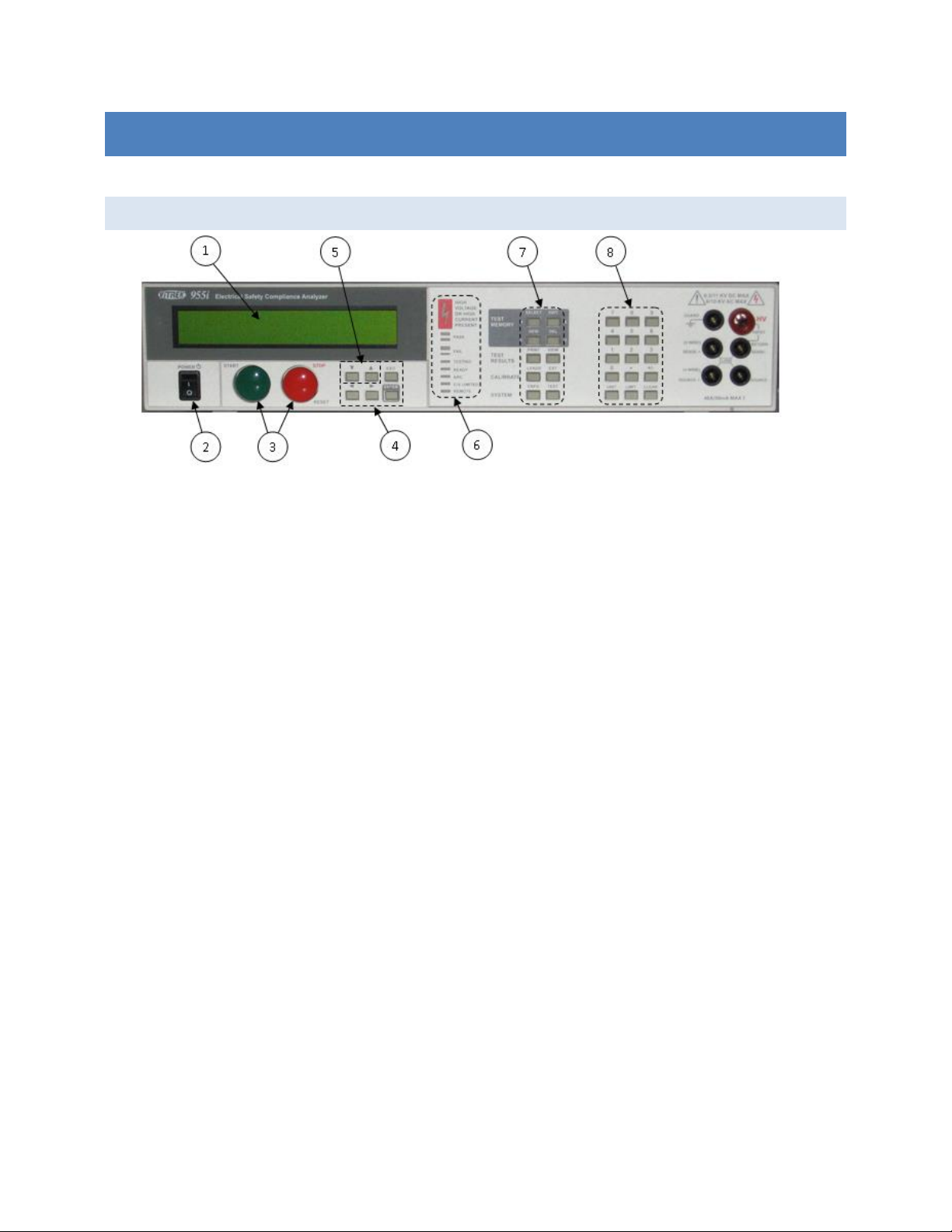
FRONT PANE L
1. The display. This shows all menus during interactive data entries, all measurements during a test, and the
present date/time when not performing any other duties.
2. The POWER switch. This turns on/off the power to the 95x.
3. The START and STOP buttons.
a. The START button allows the user to start performing a previous selected test sequence, or
(while running a test sequence) select to continue a test step when it is waiting for the user to do
so.
b. The STOP button aborts any test sequence in progress (while running a test sequence), aborts
the menu activity in progress discarding any changes made (while performing a menu), or makes
no test sequence selected (otherwise).
4. The menu selection keys. During all menus, the selected element of the menu is highlighted by flashing
between the data and blocks. These keys allow the user to move the selection point within a menu.
a. The Left and Right Arrow keys are used to move the selection point within a menu.
b. The ENTER key is used to finish entry of a menu data and automatically move to the next menu
item.
c. The EXIT key (labeled EXIT/SAVE on later units) is used to save all changes made within a menu
and return to the previous menu (if any) or to the inactive display.
5. The edit keys. These allow the user to decrement or increment a selected menu items’ value. During
numeric entry these initiate “edit” mode of data entry, rather than “direct” mode of data entry (i.e. allow
the user to adjust the existing entry using the Up/Down Arrow keys, rather than overwriting the existing
value with a new value using the numeric keys). For convenience, these keys auto-repeat if the user
maintains pressure on them.
6. The indicators.
a. HIGH VOLTAGE OR HIGH CURRENT PRESENT. This is illuminated whenever the 95x has a high
voltage (>30V) or a high current (>5A) present on its’ terminals.
Page 21 of 154

95x Series Operating Manual - June 27, 2016
b. PASS. This is illuminated whenever a test sequence is passing (while running a test sequence) or
it has passed all test steps (following completion of the test sequence).
c. FAIL. This is illuminated whenever a test sequence is failing (while running a test sequence) or
the previously run test sequence has failed any test steps (following completion of the test
sequence).
d. TESTING. This is illuminated when the 95x is running a test sequence.
e. READY. This is illuminated after the user has selected a test sequence to run and the 95x is ready
to perform that test sequence.
f. ARC. This is illuminated whenever the 95x is detecting an arc current while running a test
sequence and the specific test step is enabled to detect arc current.
g. C/V LIMITED. This is illuminated when the 95x output is either current or voltage limited by the
load while running a test sequence. This is only used in certain types of test steps.
h. REMOTE. This is illuminated when the 95x is under the control of an interface (i.e. RS232,
Ethernet or GPIB). If the user wishes to return to front panel control of the 95x the CNFG key
should be pressed to achieve this.
7. The menu keys. These initiate a menu allowing the user to perform certain activities via the front panel of
the 95x. Many of these can be disabled by the user by requiring a password in order to utilize them.
a. SELECT. Initiates a menu allowing the user to select a test sequence which has already been
defined in the 95x. This never requires a password.
b. EDIT. Initiates a menu allowing the user to select an existing test sequence and then edit it.
After editing it is automatically made ready to run. This optionally requires a password.
c. NEW. Initiates a menu allowing the user to select a presently undefined test sequence number
and name, and then to create the sequence of tests to be performed. This optionally requires a
password. While editing or creating a test sequence, this key is also used to insert a new test
step into the test sequence.
d. DEL. Initiates a menu allowing the user to select an existing test sequence and delete it from the
95x. This optionally requires a password. While editing or creating a test sequence, this key is
also used to delete a test step from the test sequence.
e. PRINT. If option UL-2 or GUL-3 is fitted and a suitable printer is attached, this key causes a
printout to be generated. This never requires a password. The printout generated is dependent
on the menu (if any) which is active when the key is pressed –
i. If pressed while no menu is active, or the configuration menu is active, a configuration
printout is generated.
ii. If pressed while selecting an existing test sequence, a test sequence printout is
generated.
iii. If pressed while reviewing the results of a completed test sequence, a test results report
printout is generated. The 95x can also be configured to automatically produce this
printout if desired.
f. VIEW. Initiates a menu allowing the user to either –
Page 22 of 154

95x Series Operating Manual - June 27, 2016
i. If no test sequence is ready to run. View the pass and fail counts for any defined test
sequence, and optionally to clear them. This never requires a password except
(optionally) to clear the counts.
ii. If a test sequence has been run and is still selected. View the test results of each step
within the previously run test sequence. This is automatically performed after a test
sequence has been run. This never requires a password.
g. LEADS. Allows the user to run the presently selected test sequence in Lead Compensation mode.
This allows the 95x to store any load offsets for each step in the test sequence and to correct all
future tests using that test sequence for these load offsets. This optionally requires a password.
h. EXT. Allows the user to perform either an adjustment or verification calibration of the 95x
against external standards. This optionally requires a password (this is separate to the other
menu activity password).
i. CNFG. Initiates a menu allowing the user to configure the 95x. This uses a series of sub-menus.
This optionally requires a password.
j. TEST. Shows the present operational status of the 95x and allows the user to perform internal
operation verification (this optionally requires a password).
8. The data entry keys.
a. The numeric keys (0 through 9), decimal point and change sign keys. These are used during
numeric or character data entry. NOTE – during hexadecimal or character data entry, certain of
the menu keys can be used for entry of the A through F characters.
b. The UNIT key. This is used to change the units during numeric data entry, and is also used while
running a test, or while reviewing test results, to change the displayed test result measurement.
c. The LIMIT key. This is used during numeric data entry to set a value to the largest possible.
When setting test dwell times this sets that the dwell should be user terminated rather than
automatically terminated after the entered time. When setting a resistance type upper limit, this
allows the user to set that there is no upper limit.
d. CLEAR key. This is used to clear an entry during numeric or character data entry.
ME NU O PERATION AND DAT A ENTRY
Most user activities using the front panel controls are performed using menus. All menus use the same general
operating methods described in this section. The user should read this section before attempting to operate the
95x.
BAS E ME N U S T ATE
When the 95x is not performing a menu and is not performing a test sequence, the display shows the model # in
the uppermost display line and the date and time in the lower most display line, this is called the base menu state
in this document. Most menus require the 95x to be in the base menu state to be initiated, an example of the
base menu state display is -
ViTREK 951i
9-Feb-10 9:08:51am
If the 95x is not in this state and the user is unsure how to return to this state, then pressing the STOP button will
accomplish this (in some circumstances the STOP button may need to be pressed more than once).
Page 23 of 154

95x Series Operating Manual - June 27, 2016
NAV IGAT ING M ENUS
The present selection point in a menu is denoted by the displayed information flashing between the
information and solid blocks.
The user can move the selection point in a menu by using the Left and/or Right Arrow keys.
o The Right Arrow key moves the selection point further down the menu. Moving the selection
point past the last selectable item in a menu selects the first selectable item in the menu (a
double beep sound is made when this occurs).
o The Left Arrow key moves the selection point further up the menu. Moving the selection point
before the first selectable item in a menu selects the last selectable item in the menu (a double
beep sound is made when this occurs).
Although the 95x display is limited to two lines, most menus have more lines than this. The display is
automatically scrolled up and down the menu to display the menu line containing the present selection
point.
Not all menus or menu lines may be available.
o Generally items which are not pertinent to the specific model or option content of the 95x are
not shown.
o All menus in the 95x utilize a “top down” priority. Selections or entries made may affect
subsequent entries in the menu. Entries may be limited in allowable values, or may not be
shown.
If a menu line is an entry into a sub-menu, then the left side of the line shows descriptive text followed by
an ellipsis character (…). The descriptive text is selectable. If the user presses the ENTER key while a sub-
menu entry line is selected then the sub-menu is opened.
o When a sub-menu is terminated by pressing the EXIT key then the user is returned to the
preceding level of menu.
o If any level of sub-menu is terminated using the STOP button then all levels of menus are aborted
and any changes made at any level are discarded.
o Only when the base level menu is terminated by pressing the EXIT key are any changes made
actually saved.
If a menu line is for informative purposes only, then the left side of the line shows descriptive text
followed by a colon character with the informative data at the right end of the line. The descriptive text is
selectable.
If a menu line allows the user to edit its’ contents, then the left side of the line shows descriptive text
followed by a colon character with the editable data at the right end of the line. The editable data is
selectable; some menu lines may contain more than one editable data.
MOD IFYI N G ME NU E NTRI ES
In many places the available contents of entries in different menu lines are inter-related. The 95x uses a
“top down” menu approach; the topmost contents in a menu may limit the available entries in the menu
below them, but not vice versa. Generally the user cannot set a limit or an output which the specific
model and option content of the 95x is not capable of achieving.
Page 24 of 154

95x Series Operating Manual - June 27, 2016
Changing Numeric Data. After making the numeric data the selection point in the menu, the user can
overwrite the data by using the data entry keys. While overwriting, the selection point becomes a single
character position within the numeric data.
o A numeric key places the corresponding character and moves the selection point to the right one
position.
o Certain numeric data allow the user to change the units of the data (e.g. between current and
resistance) and/or change the multiplier for the data (e.g. select an entry in microamps or
milliamps). To change the units, press the UNIT key while the entire numeric data is selected; to
change the multiplier, press the UNIT key while entering the numeric data.
o The Left Arrow key acts as a delete key, deleting the previously entered character.
o The CLR key removes all of the existing entry and places the selection point in the rightmost
character position.
o The LIMIT key sets the numeric data to the highest possible value in most cases; while entering
the lower limit in a range pair of data the LIMIT key sets the minimum value; in some other cases
the LIMIT key has a special use denoted in the description for that specific data.
o The Right Arrow or ENTER key terminates the numerical data entry and also moves the selection
point to the right or downwards, as applicable.
Changing Multiple Choice Data. After making the multiple choice data the selection point in the menu,
the user can change the selection by repeatedly pressing the Up Arrow or Down Arrow keys until the
desired selection is displayed. The ENTER key terminates the multiple choice data entry and also moves
the selection point to the right or downwards, as applicable. The Left Arrow and Right Arrow keys
automatically terminate the multiple choice data entry prior to moving the selection point accordingly.
Changing Character Data. After making the character data the selection point in the menu, the user can
choose to either edit the existing data, or to overwrite it with new data. While overwriting or editing the
data the selection point becomes a single character position within the character data.
o Editing Existing Character Data. If the user presses the Up Arrow or Down Arrow key while the
entire character data is selected then the edit mode of entry is initiated and the leftmost
character of the existing data is selected. Character data uses a limited character set; A through
Z, a through z, 0 through 9, the space character and most punctuation characters.
The Up Arrow and Down Arrow keys change the selected character to the next or
previous available character in the character set.
The numeric keys and the A through F keys overwrite the selected character.
The Left Arrow and Right Arrow keys move the selection point within the character data
area.
The CLR key aborts the edit, the character data is cleared, and the overwrite mode is
initiated.
The ENTER key exits the edit mode retaining the changes made.
o Overwriting Character Data. If the user presses any of the numeric keys or the CLR key then the
overwrite mode of entry is initiated, starting with the corresponding character and with the
leftmost character.
Page 25 of 154

95x Series Operating Manual - June 27, 2016
The Up Arrow and Down Arrow keys change the selected character to the next or
previous available character in the character set.
The numeric keys and the A through F keys places the corresponding character and
moves the selection point to the right one position.
The Left Arrow key acts as a delete key, deleting the previous character and moving the
selection point to the left one position.
The Right Arrow key places a space character and moves the selection point to the right
one position.
The CLR key removes all of the existing entry and places the selection point in the
leftmost character position.
The ENTER key terminates the character data entry retaining the changes made and also
moves the selection point in the menu to the right or downwards, as applicable.
Changing Hexadecimal Data. Hexadecimal data is treated exactly the same as character data (see above)
but with the available character set restricted to 0 through 9 and A through F.
ADJUST ING THE DISPLAY CONT RAST
The user can adjust the display contrast while the 95x is in the base menu state (i.e. the display shows the model
number and the time/date). An example display when the user can adjust the display contrast is –
ViTREK 951i
9-Feb-10 9:08:51am
Using the Up and Down Arrows keys, select the display contrast which best suits the users normal viewing position.
NOTE – it may be possible to adjust the display contrast such that the display is not visible. If the display appears
to be totally blank then press and hold the Down Arrow key to return it to the visible state; if the display appears
to have all of its dots “black” then press and hold the Up Arrow key to return it to the visible state.
NOTE – it may be best to select the contrast which shows the least “blurring” when the seconds digit in the
displayed time changes. This has been found to produce the best adjustment for viewing angle as well as contrast.
LOCKIN G AN D UN LOCKING MENU S
Many menus in the 95x can be locked by a user, preventing unauthorized changes to test sequences and
configuration settings via the front panel of the 95x. When initially delivered from the factory, this capability is
disabled.
The password is any combination of six 0 through 9 and A through F characters. The password 000000 indicates a
cleared password, disabling this capability until a non-zero password is subsequently set by the user.
If a menu lock password has been set, the 95x always powers up with the menus locked.
UNL OCKI N G M ENUS
If the menu lock password has been set, a user must enter this password to unlock a menu. The user is prompted
to enter the password when needed; which is accomplished by using the 0 through 9 and A through F keys as
needed to match the previously set password, followed by the ENTER key. After successfully entering the
password the front panel menus remains unlocked until the menus are relocked by the user or the 95x is power
cycled. Note that the 95x display does not show the characters during unlock password entry for security reasons.
Page 26 of 154

95x Series Operating Manual - June 27, 2016
SET TING , CH A NGIN G OR CLEA RING A MEN U LOC K PAS SWOR D
Ensure that the display indicates that the 95x is in the base menu state, i.e. the display shows the date
and time. If necessary press the STOP button to abort a menu and return to the base menu state.
Press the CNFG key. If a password has been already set and the menus are not already unlocked, the user
must enter the correct password to unlock the menu at this point.
The display now shows the main configuration menu. An example of which is as follows –
TEST…
PRINTOUT…
SYSTEM…
INTERFACES…
DIGITAL I/O…
BUILD…
SET TO DEFAULTS…
LOCK PASSWORD:000000
RELOCK…
Using the Left Arrow or Right Arrow keys as needed, change the selection point to the LOCK PASSWORD
line.
Using the 0 through 9 keys and/or the A through F keys, enter a six character password. If the password
000000 is set then this clears the password and disables menu locking.
Press the ENTER key.
If a non-zero password was entered, the display now shows a message indicating that the front panel is
now locked and returns to the base menu state. Otherwise, a message is displayed indicating that the
menu lock is now disabled and the 95x stays in the main configuration menu.
REL OCKI N G M E NUS
If the menu lock password has been set but the menus are presently unlocked (i.e. they have been previously
unlocked as described above) then the user may relock the menus as follows –
Ensure that the display indicates that the 95x is in the base menu state, i.e. the display shows the date
and time. If necessary press the STOP button to abort a menu and return to the base menu state.
Press the CNFG key.
The display now shows the main configuration menu. An example of which is as follows –
TEST…
PRINTOUT…
SYSTEM…
INTERFACES…
DIGITAL I/O…
BUILD…
SET TO DEFAULTS…
LOCK PASSWORD:000000
RELOCK…
Using the Left Arrow or Right Arrow keys as needed, change the selection point to the RELOCK line.
Press the ENTER key.
The display now shows a message indicating that the front panel is now locked and returns to the base
menu state.
Page 27 of 154

95x Series Operating Manual - June 27, 2016
UNK NOWN MEN U LOC K PAS S WORD
If the 95x menus have been locked but the password is unknown, the user should contact Vitrek for assistance.
The 95x has an internal set of “one time use” passwords for this circumstance.
DISPLA YING BUI LD I NFORMATION
Ensure that the display indicates that the 95x is in the base menu state, i.e. the display shows the date
and time. If necessary press the STOP button to abort a menu and return to the base menu state.
Press the CNFG key.
The display now shows the main configuration menu, an example of which is –
TEST…
PRINTOUT…
SYSTEM…
INTERFACES…
DIGITAL I/O…
BUILD…
SET TO DEFAULTS…
LOCK PASSWORD:000000
RELOCK…
Using the Left Arrow or Right Arrow keys as needed, change the selection point to the BUILD line.
Press the ENTER key.
The 95x now displays the build configuration menu, an example of which is –
SERIAL# 123456
FIRMWARE: v1.12
FP: v1.10
MEAS: v1.10
DRIVE: v1.10
BASE UNIT: 951i
DC OPTION: NONE
AC2 OPTION: NO
AC30 OPTION: NO
500VA OPTION: NO
PMT1 OPTION: YES
HSS OPTION: NO
MAX DC: 6.5KV
MAX AC: 6.0KV
INTERFACE: GUL-3
UPGRADE:000000000000
The user may navigate this menu but may not make changes to it. The information available is as follows-
o SERIAL#. This shows the serial number of this 95x.
o FIRMWARE. This shows the main firmware revision number installed in this 95x. This can be
upgraded (along with the MEAS and DRIVE firmware) by the user via the RS232, Ethernet or GPIB
interface. Contact Vitrek or your local representative for details regarding this.
o FP. This shows the front panel firmware revision number.
o MEAS. This shows the Measurement DSP firmware revision number installed in this 95x.
o DRIVE. This shows the Output Drive DSP firmware revision number installed in this 95x.
o BASE UNIT. This shows the base model number of this 95x.
Page 28 of 154

95x Series Operating Manual - June 27, 2016
o DC OPTION. This shows if option NODC or DCNEG is installed in this 95x.
o AC2 OPTION. This shows if option AC-2 is installed in this 95x.
o AC30 OPTION. This shows if option AC-30 is installed in this 95x.
o 500VA OPTION. This shows if option 500VA is installed in this 95x.
o PMT1 OPTION. This shows if option PMT-1 is installed in this 95x.
o HSS OPTION. This shows if option HSS or HSS-2 is installed in this 95x.
o INTERFACE. This shows if option UL-2 or GUL-3 is installed in this 95x.
o MAX DC. This shows the factory limit on the maximum DC Voltage generated by this unit.
o MAX AC. This shows the factory limit on the maximum AC Voltage generated by this unit.
o MAX GB. This shows the factory limit on the maximum Ground Bond current generated by this
unit.
o UPGRADE. This allows the user to enter a factory supplied code to upgrade their instrument to
enable additional options which were not enabled as originally purchased.
When finished reviewing the build information, press the EXIT key to return to the main configuration
menu, and then press EXIT again (if no additional configuring is to be performed) to exit the main
configuration menu.
SY STEM CONFIG URAT ION SETTINGS
There are several system configuration settings available which affect the overall operation. These can be viewed
or set as follows –
Ensure that the display indicates that the 95x is in the base menu state, i.e. the display shows the date
and time. If necessary press the STOP button to abort a menu and return to the base menu state.
Press the CNFG key.
The display now shows the main configuration menu, an example of which is –
TEST…
PRINTOUT…
SYSTEM…
INTERFACES…
DIGITAL I/O…
BUILD…
SET TO DEFAULTS…
LOCK PASSWORD:000000
RELOCK…
Using the Left Arrow or Right Arrow keys as needed, change the selection point to the SYSTEM line.
Press the ENTER key.
The 95x now displays the system configuration settings menu, an example of which is –
KEY BEEPS: SOFT
TIME FORMAT: 12hr
SET TIME: 9:18:06am
SET DATE: 9-Feb-10
The user may navigate this sub-menu and change the displayed settings as required.
Page 29 of 154

95x Series Operating Manual - June 27, 2016
o KEY BEEPS. This allows the user to set the volume of the beep sounds made by the 95x
whenever a key is pressed.
o TIME FORMAT. This allows the user to select whether the 95x displays time in 12hour or 24hour
format.
o SET TIME. This allows the user to adjust the presently displayed time. The hour, minute and
second are separately adjusted using the Up and Down Arrow keys.
o SET DATE. This allows the user to adjust the presently displayed date. The day, month and year
are separately adjusted using the Up and Down Arrow keys.
When finished, press the EXIT key to exit this sub-menu, and then press EXIT again (if no additional
configuring is to be performed) to exit the main configuration menu and save the settings.
RETURNING ALL CON FIGUR ATIO N SETTINGS TO FACTORY DEFAU LTS
The user may return all configuration settings to the factory default settings as follows –
Ensure that the display indicates that the 95x is in the base menu state, i.e. the display shows the date
and time. If necessary press the STOP button to abort a menu and return to the base menu state.
Press the CNFG key.
The display now shows the main configuration menu, an example of which is –
TEST…
PRINTOUT…
SYSTEM…
INTERFACES…
DIGITAL I/O…
BUILD…
SET TO DEFAULTS…
LOCK PASSWORD:000000
RELOCK…
Using the Left Arrow or Right Arrow keys as needed, change the selection point to the SET TO DEFAULTS
line.
Press the ENTER key.
The 95x now displays a message temporarily and remains in the main configuration menu, allowing the
user to override the factory settings as needed. If no further changes are needed, press the EXIT key to
save the changes and return to the base menu state.
Page 30 of 154
 Loading...