

Vitrek 944i Operating & Maintenance Manual
944i Dielectric Analyzer
Operating & Maintenance Manual
Vitrek Corporation
9880A Via Pasar, San Diego, CA 92126 USA
V: 858 689 2755 F: 858 689 2760
Copyright Vitrek Corporation 1992-2008, all rights reserved, rev 2008-04-23
Table of Contents
Advanced Test Equipment Rentals
www.atecorp.com 800-404-ATEC (2832)
®
E
s
t
a
b
l
i
s
h
e
d
1
9
8
1

Introduction .........................................................................................................1
Certification & Warranty Statement ....................................................................... 1
Safety Precautions ..................................................................................................2
1 Getting Started
Unpacking............................................................................................................... 3
Initial Adjustments..................................................................................................3
Front Panel Layout .................................................................................................4
Rear Panel Layout...................................................................................................5
Instructions for Bench Use .....................................................................................6
Instructions for Rack Mounting..............................................................................6
Earth Ground Connection .......................................................................................6
Current Detection Circuitry ....................................................................................6
2 Direct Mode Operation
DC Dielectric Strength Testing...............................................................................7
AC Dielectric Strength Testing...............................................................................8
Insulation Resistance (Megaohm) Measurement....................................................10
Earth Continuity (Low Ohms) Measurement..........................................................11
3 Automatic Mode Operation
DC Dielectric Strength Testing...............................................................................13
AC Dielectric Strength Testing...............................................................................15
Insulation Resistance (Megaohm) Measurement....................................................17
Earth Continuity (Low Ohms) Measurement..........................................................18
Adding Test Steps...................................................................................................19
Storing Tests ........................................................................................................... 19
Recalling Tests........................................................................................................20
Editing Tests ........................................................................................................... 20
Printing Test Reports ..............................................................................................21
Aborting Tests ........................................................................................................21
4 Test Connections
Test Connection Safety Precautions .......................................................................23
Connecting to Earth Grounded Devices .................................................................23
Connecting to Non-Grounded Devices...................................................................24
Typical Electrical Safety Test Connection .............................................................25
5 Systems Controls
Running Self Tests.................................................................................................. 27
Setting System Clock.............................................................................................. 28
Beeper Control........................................................................................................ 28
Selecting Arc Sensitivity ........................................................................................28
Enabling Auto Ground Testing...............................................................................29
Enabling Ramp Down.............................................................................................29
Ramp Current Limit................................................................................................29
Safety Interlock.......................................................................................................30
Front Panel Lockout ..............................................................................................30
Pass/Fail Counters .................................................................................................30

6 Remote Operation
Option IF-4 Interface Card Description .................................................................. 31
IEEE-488.2 (GPIB) Programming..........................................................................31
RS-232C Communication Port ...............................................................................38
Parallel Printer Port.................................................................................................39
Vitrek Instrument Control Loop (VICL) ................................................................39
7 Options and Accessories
Description of Optional Items.................................................................................40
8 Maintenance
Routine System Inspection and Maintenance .........................................................42
Verification Procedure............................................................................................43
Performing an External Auto-Calibration............................................................... 45
EPROM Upgrade Procedure................................................................................... 48
9 Specifications
944i Performance Specifications ............................................................................50

Introduction
The Vitrek 944i Dielectric Analyzer combines the four basic dielectric tests into one compact, easy to use, feature-rich instrument.
The 944i's standard multi-function capabilities include - AC and DC Dielectric strength testing, Insulation Resistance (IR)
measurement to 100 gigaohms and Earth Continuity measurement down to 10 milliohms. All of these tests can be run in either
manual or automatic mode, as well as, via remote control using the optional IEEE-488.2 (GPIB), RS-232C or parallel
communication ports.
Vitrek has taken advantage of advanced microprocessor and ASIC technologies in order to reduce the size and complexity of the
944i while increasing reliability and functionality when compared to traditional hi-pot testers. Operating the 944i is easier than
ever due to extensive menu prompting on the unit's brilliant 40 character back-lit LCD. Built-in test procedure storage and edit
capability increases test throughput and reduces test development time. Internal diagnostics ensure that the 944i is properly
functioning at all times while the automatic calibration capability maintains highest possible systems accuracy.
Read the Vitrek 944i manual carefully before operating the instrument. Should you have any questions, Please contact your local
Vitrek Service Center or Vitrek Customer Satisfaction Department at 9880A Via Pasar, San Diego, CA 92126 phone (858)6892755 fax (858)689-2760.
Certification
Vitrek Corporation certifies that this instrument was thoroughly tested and inspected and found to meet published specifications
when shipped from the factory. Vitrek Corporation further certifies that the calibration of this instrument is traceable to the
National Institute of Standards and Technology to the extent allowed by NIST's calibration facility.
Limited Warranty
The warranty period for this instrument is stated on your invoice and packing list. Please refer to these documents to
determine appropriate warranty dates. Vitrek warrants to the original purchaser that this product will be free from defects in
material and workmanship under normal use throughout the warranty period. Vitrek Corporation's liability under this
warranty is limited solely to the repair or replacement of this instrument during the warranty period, provided it is returned to
the factory freight prepaid with return authorization number. And provided that such defects are not determined by Vitrek to
have been caused by abuse, misuse, alteration, improper installation, neglect or environmental conditions. No other warranty
is expressed or implied. Vitrek Corporation is not liable for incidental, consequential, direct or indirect damages or for costs,
losses or expenses of any kind. A return authorization number must be obtained directly from the factory for warranty
repairs. No liability will be accepted if returned without factory authorization number.
1

Safety Precautions
The following general safety precautions must be observed during all phases of operation, service and repair of this
instrument. Failure to comply with these precautions or with specific warnings elsewhere in this manual violates safety
standards of design, manufacture and intended use of the instrument. Vitrek Corporation assumes no liability for the
customer's failure to comply with these requirements.
GROUND THE INSTRUMENT
To minimize shock hazard, the instrument must be connected to an electrical ground. This should be accomplished through the
earth ground pin of the instrument's power connector and power cord.
DO NOT OPERATE IN AN EXPLOSIVE ATMOSPHERE
Operation of any electrical instrument in the presence of flammable gases, fumes or particles constitutes a definite safety hazard.
DO NOT REMOVE COVERS
Operating personnel must not attempt component replacement or internal adjustment. Dangerous voltages may exist internally
even when the power is switched off. Because of the dangers of introducing additional hazards, do not install substitute parts or
perform any unauthorized modifications to the instrument. Refer the unit to qualified maintenance personnel or to your nearest
Vitrek service center.
DO NOT OPERATE ALONE
Do not attempt to operate the instrument at high voltages unless another person, capable of rendering first aid and resuscitation, is
present.
DANGER! HIGH VOLTAGE
Use extreme caution when working with high voltages. Never remove or insert test leads from the 944i while high voltage is
present. Only use test lead materials which have adequate high voltage ratings. Inspect test leads regularly for signs of wear and
abrasion.
READ AND UNDERSTAND THE MANUAL
Prior to operating this instrument, the user must be familiar with the operating procedures, controls and precautions.
2

Unpacking
If the shipping carton is damaged, request that the carrier's agent be present when the instrument is unpacked. If the instrument
appears damaged, notify the carrier's agent for repair authorization before returning the instrument to Vitrek.
It is also necessary to notify Vitrek and receive a RETURN MATERIALS AUTHORIZATION number before returning the
instrument.
Even if the instrument appears undamaged, it may have suffered internal damage in transit that may not be evident until operated
or tested to verify performance. If the instrument fails to operate, notify the carrier's agent and Vitrek or your local Vitrek Service
Center. Retain the shipping carton for the carrier's inspection.
.........................................................................................
Initial Adjustments
The only adjustments required prior to operation of the 944i are selection of the local power source voltage and verification that
the correct fuse for this voltage is fitted. The supply voltages and fuses are listed below:
105 to 128VAC 50/60Hz 5 Amp slow blow fuse
210 to 256 VAC 50/60Hz 2.5 or 3 Amp slow blow fuse
Unless specifically requested, all units shipped to North American locations are factory set for 115VAC. Check the rear panel
mounted selector switch to ensure that the proper line voltage is selected prior to applying power to the 944i.
.........................................................................................
3
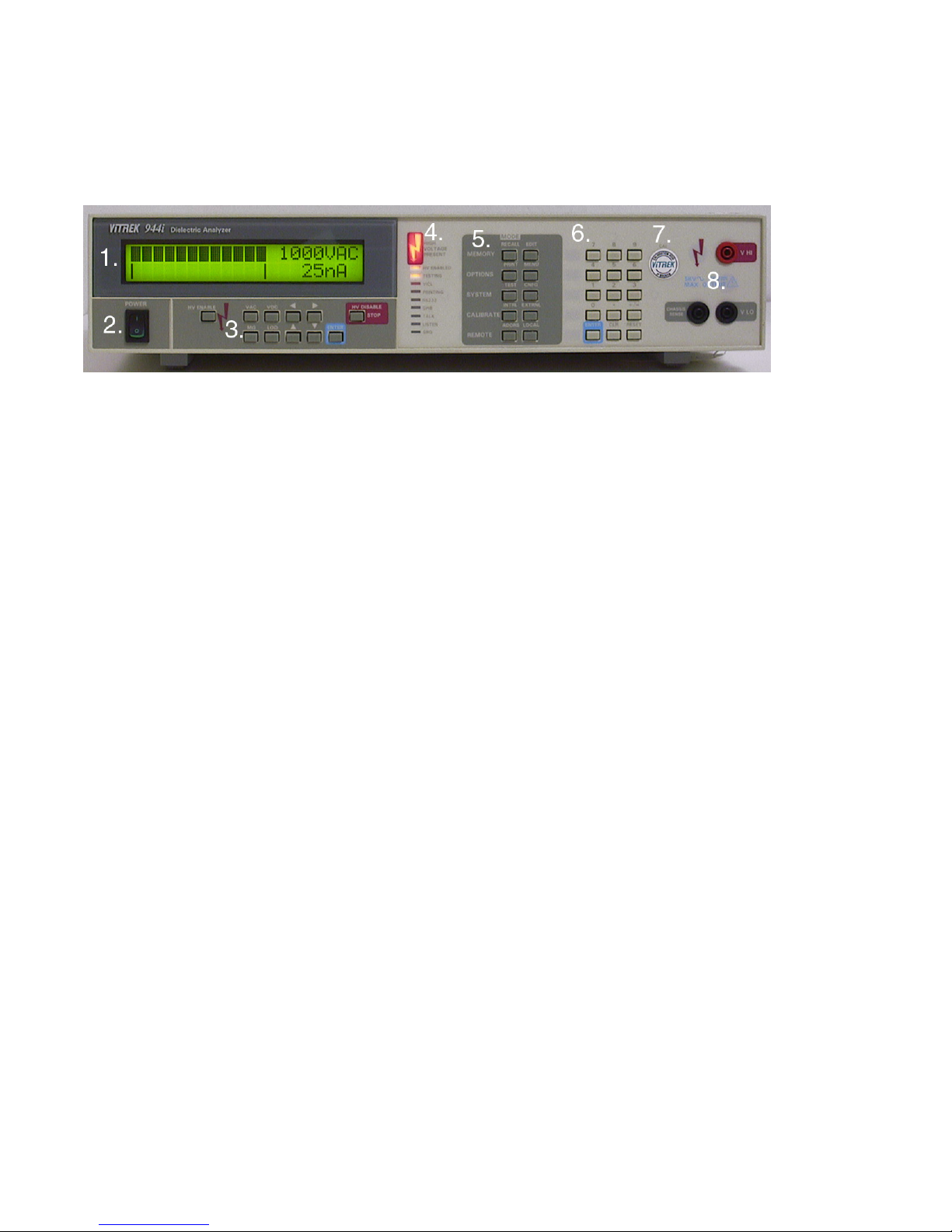
Front Panel Layout
1. Main Display 5. Mode Keys
2. Power Switch 6. Numeric Entry Keys
3. Function Keys 7. Calibration Enable Switch
4. L.E.D. Indicators 8. Measurement Terminals
Main Display - The 944i utilizes a 2 row by 20 Character, alphanumeric, backlit LCD.
Power Switch - The 944i features an ergonomic, rocker style power switch.
Function Keys - The keypad grouping immediately below the main display contains 11 function keys. The functions are (from
left to right, top row first): High Voltage Enable, VAC (AC Dielectric), VDC (DC Dielectric), Left Arrow, Right Arrow, High
Voltage Disable, Megaohms (Insulation resistance), Low-ohms (Continuity), Up Arrow, Down Arrow and Enter. The High
Voltage Disable key is highlighted in bright red for easy identification. This key may be used at any time to disable the high
voltage output and return the instrument to a safe operating state.
L.E.D. Indicators - The 944i is equipped with 10 front panel L.E.D. status indicators. They are (from top to bottom): High
Voltage Present, High Voltage Enabled, Testing, VICL Port Active, Printing, RS232 Active, GPIB Remote, Talk, Listen and SRQ
(remote service request).
Mode Keys - The two columns of keys to the right of the status indicators are the mode keys.
left to right, top row to bottom row) is as follows: Recall Test Program, Edit Test Program, Print, Menu, System Test, System
Configuration, Internal Calibration, External Calibration, GPIB Address and Local.
Numeric Entry Keys - The numeric entry keys are located to the right of the mode keys. They consist of 0 through 9, +/-, Decimal
Point (.), Enter, Clear and Reset.
A listing of the 10 mode keys (from
Calibration Enable Switch - The calibration enable switch is recessed behind the front panel and is located to the right of the
numeric entry keys. The calibration enable switch may be secured by a calibration sticker which must be broken in order to
engage the switch.
Measurement Terminals - The 944i is designed with three safety sheathed banana plug receptacles for stimulus and measurement.
Warning! Terminals provide dangerous and potentially lethal voltages. Read and understand all safety precautions before
connecting to these measurement terminals.
4
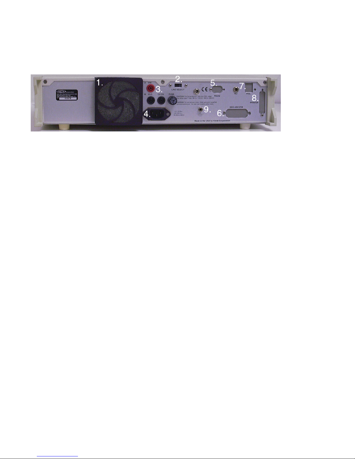
Rear Panel Layout
1. Fan Filter Assembly 6. IEEE-488 Port
2. Line Voltage Selector 7. VICL/ SIJ Ports
3. Rear Panel Terminals 8. Parallel Printer Port
4. Line power Receptacle 9. Chassis Ground Terminal
5. RS232 Port
Fan Filter Assembly - The 944i uses a removable fan filter to clean the air used for cooling. Refer to the maintenance section of
this manual for instructions on periodic removal and cleaning.
Line Voltage Selector - To select between 115 and 230 VAC line voltage operation, the 944i provides a built-in line voltage
selector switch. Refer to the initial settings instructions, located earlier in this section of the manual, prior to changing switch
positions.
RPO Rear Panel Output Terminals - The 944i may be optionally equipped with rear output terminals for applications (such as rack
mounting) where this feature is desirable and convenient.
Line Power Receptacle - Power is provided to the 944i through a three-prong internal type power receptacle. A power cord,
which mates with this receptacle, is also provided.
RS232 Port - The 944i uses a 9-pin male "D" sub connector for serial communications when the option IF-4 interface package is
ordered.
IEEE-488 Port - Access to the optional IEEE-488/ GPIB interface is accomplished through this connector.
VICL/SIJ Ports - The 944i is configured with a proprietary serial control ports when the IF-4 interface package is ordered. This
serial port is provided to communicate with auxiliary instruments such as the 930i Ground Integrity Tester. The SIJ port is
optionally available for connection to safety interlock devices (i.e. palm switches or micro-switches)
Parallel Printer Port - To output data to an Epson FX-80 compatible parallel printer, the 944i utilizes a standard 25 pin "D" sub
connector. The parallel printer capability is part of the IF-4 interface package.
Chassis Ground Terminal. This binding post provides convenient access to the 944i's chassis ground. The chassis ground
terminal is used in the process of calibrating the 944i.
.........................................................................................
.
5

Instructions for Bench Use
The 944i is delivered ready for bench operation. The unit is equipped with front tilt feet to adjust viewing angle. The 944i is also
equipped with side handles to assist in carrying the unit. Use caution when lifting, the 944i is surprisingly heavy. Hold handles
toward the rear of the unit for best balance. Always verify that the power cord is equipped with a three terminal connector before
applying power to the 944i.
.........................................................................................
Instructions for Rack Mounting
Optional rack mounting brackets are available for mounting the 944i in a standard 19" equipment rack. The size and weight of the
944i require that the unit should be supported on both sides along its entire length by the use of trays or slides. If it is to be
transported while mounted in a rack, it must be supported to prevent upward or downward movement.
To install the RM-1 rack mount kit, remove the two forward flathead screws on each side of the 944i. Position the rack ears in
place and install with the provided 5/8 inch 8-32 flathead screws. CAUTION! Longer screws may damage the unit. The
specifications for the 944i become degraded at high temperatures, therefore it is recommended sufficient room be allowed for
airflow around the 944i. This may be achieved by placing at east 1.75" high blank panels above and below the 944i in the rack.
Under no circumstances should the ambient air temperature surrounding the 944i be allowed to exceed 50° C while in operation or
70° C while not in operation.
Earth Ground Connection
The power connector should be a three-contact device meeting the safety requirements of the area in which the 944i is to be used
and should only be mated with a three-contact connector where the third contact provides ground connection. If the power is
provided through an extension cable then the ground connection must be continuous throughout this cable to the 944i.
FAILURE TO PROVIDE A CONTINUOUS GROUND CONNECTION T O THE 944i MAY RENDER THE UNIT
UNSAFE FOR USE.
Current Detection Circuitry
The 944i is equipped with three separate circuits for the monitoring and measurement of the output current. For precision
measurement, the 944i utilizes an RMS measurement circuit based on a 12 bit ADC. When load failures are detected using the
RMS circuit, a typical failure message would be "failed-max I" or "failed-min I".
For high-speed detection of load breakdown, the 944i utilizes a peak current comparator circuit which is set to trip at
approximately 50 mA peak. When sudden breakdown occurs, the peak detection circuit will generally trigger before the slower,
precision RMS measurement circuit. The failure message for the over current circuit is "Failed-OVR Current".
The final circuit which the 944i contains for catching load failures is a user programmable arc detector. The arc detector checks
for small current pulses using a DIDT comparator circuit. The user selectable arc detection modes of "fast", "medium", and
"slow" equates to arc pulse width of approximately 3, 10 and 30 micro seconds. The failure message of the arc detector is "FailedArc".
6

Operating the Vitrek 944i in direct mode permits the user to manually control the output up or down while monitoring the leakage
current being drawn by the load. When operating in the direct mode the user is in full control of the measurement process - ramp
rate and dwell time are a function of how fast the user changes the output voltage and how long the user chooses to stay at that
setting. Voltage and current limits are set by the user to prevent accidental excursion beyond those preset points.
DC Dielectric Strength Function
In evaluating the ability of materials to insulate against the flow of electricity, the DC Dielectric Strength Test is extremely
valuable. The DC test function specifically analyzes the ability of a material to resist the flow of direct current in the presence of a
high voltage. Other common names for the DC Dielectric strength test include: DC Hipot, DC Voltage Breakdown and DC
Voltage Withstand.
To gain access to the DC Dielectric test mode, simply press the VDC button located under the display window. Upon pressing the
VDC button, the following display prompt will appear:
DC DIELECTRIC TEST
DIRECT AUTOMATIC
This message confirms that the DC function has been selected and offers two different operating modes. By using the left/right
cursor arrows, one can alternatively highlight either Direct mode or Automatic mode.
Direct mode permits manual operation and is highlighted when the Direct/Automatic menu pops-up. To select Direct mode,
simply press enter. The following prompt will appear:
ENTER MAX VOLTAGE
1000 VOLTS
This prompt allows the operator to set a maximum test voltage. This limit prevents the user from inadvertently exceeding the
intended range of output voltage. The 1000 VDC shown is the default limit. To enter another limit, simply press the number keys
for the desired value. The range of limits for the VDC function may be as low as 100 VDC or as high as 5000 VDC. Once the
desired voltage limit is displayed, press enter to advance to the next step.
The last setup prompt in VDC direct mode is the current limit prompt as shown below:
ENTER MAX CURRENT
10.0 mA
This value sets the maximum amount of leakage current, which the 944i will source without shutting down the test. Any current,
which exceeds this limit, will cause the unit to automatically stop the test. The default value is 10.0 mA. However, any value
between 100 nA and 35 mA may be used. To change the value of the current limit, use the number keypad. To change the units
from m (milli) to u (micro) or n (nano), use the up/down cursor arrows. Once the desired maximum current limit is displayed,
press enter to complete the test set-up for VDC Direct mode.
For safety purposes, the 944i requires a two-step key press sequence prior to initiating high voltage testing. Before beginning
this sequence, it is important to ensure that the device under test is properly connected to the 944i test terminals. Please refer
to the "
Test Connections" section of the operating manual before proceeding.
7

WARNING!: failure to observe test connection precautions may result in severe injury or death to the operator. The
display will prompt the user to press the HV enable key as follows:
HIGH VOLTAGE ENABLE
REQUIRED
Once the test connections have been verified, press the HV enable button. After pressing the high voltage enable key the final
prompt is:
PRESS ENTER TO
START TEST
Upon pressing the enter key the 944i will sound a number of warning beeps while flashing the HV enable indicator. If the user
has enabled the auto-ground test feature of the 944i, the unit will automatically check the chassis of the DUT for earth ground
continuity before applying high voltage to the DUT.
Whenever any voltage greater than 80 volts is applied to the output terminals, the high voltage present indicator will automatically
illuminate. The starting point for all direct high voltage tests is at 100V. The test display is arranged with the top row indicating
the output voltage in both digital read-out and bar graph formats. The multi-segment bar graph represents the proportion of output
voltage relative to the preset voltage limit. For example, if the output setting was 500 volts and the preset voltage limit was 2500
volts approximately 20% of the bar graph segments will be illuminated.
Adjacent to the bar graph is a digital display of the output voltage setting. The display is a four-digit display with a resolution of
one volt. The digit that is blinking is the digit that is presently subject to modification by the up/down cursors. To increase the
output voltage, press the up arrow. To decrease the output, press the down arrow. To move the blinking digit to the left or right,
use the left/right cursors.
If at any time during direct output control the preset maximum current limit is exceeded, the
maximum current exceeded message will be displayed. When the user has completed direct mode testing, press the High Voltage
Disable/Stop key to remove the high voltage output. ALWAYS verify that the high voltage present indicator has extinguished
prior to handling the test leads.
test is automatically aborted and a
.........................................................................................
AC Dielectric Strength Function
AC dielectric strength testing is performed to evaluate a materials ability to resist the flow of alternating current in the presence of
high voltage. The AC dielectric strength test is also commonly referred to as: AC Hipot, AC Voltage Breakdown and AC Voltage
Withstand.
To begin an AC dielectric test press VAC. The 944i will respond with the following message:
AC DIELECTRIC TEST
DIRECT AUTOMATIC
This message confirms that the AC function has been selected and offers two different operating modes. By using the left/right
cursor arrows, one can alternatively highlight either Direct mode or Automatic mode.
Direct mode permits manual operation and is highlighted when the Direct/Automatic menu pops up. To select DIRECT mode,
simply press enter. The following prompt will appear:
ENTER MAX VOLTAGE
1000 VOLTS
This prompt allows the operator to set a maximum test voltage. This limit prevents the user from inadvertently exceeding the
intended range of output voltage. The 1000 VAC shown is the default limit. To enter another limit, simply press the number keys
for the desired value. The range of limits for the VAC function may be as low as 100 VAC or as high as 5000 VAC. Once the
desired voltage limit is displayed, press enter to advance to the next step.
8

After the voltage limit has been set the 944i will prompt for a test frequency. This advanced feature, which enables the user to test
AC dielectric strength over a wide range of test frequencies, is unique to the Vitrek 944i. The frequency prompt is as follows:
SELECT TEST FREQUENCY
60 HZ 50 HZ _ _ _ HZ
Should the user desire a test frequency of 60 Hz, press enter. If 50 Hz is the desired test frequency, use the right cursor to
highlight the 50 Hz option and then press enter. When an alternate test frequency is required, use the cursors to highlight the _ _ _
Hz option and then use the number keys to fill in the frequency of interest and then press enter.
Following frequency selection, the current sense selection menu will appear as shown below:
SELECT CURRENT SENSE
REAL APPARENT TOTAL
The Vitrek 944i uses internal phase angle circuitry to determine if the leakage current being measured is a result of a resistive load
(real), reactive load (apparent) or both (total). In most applications total current is the desired sense mode and is highlighted when
the current sense prompt pops-up. To select "total" press the enter key.
In many applications involving devices with EMI filters, the current being drawn by the filter capacitor is of no interest to the
user. To ignore the current flow caused by the reactive component, select the "real" current sense mode. To determine the
amount of current flow caused by the reactive component, select "apparent" current sense.
Due to the nature of phase measurement, it is difficult to accurately determine the phase of low amplitude signals. To prevent
erroneous phase measurement under low amplitude conditions, the 944i will automatically default to "total" current sense when
phase signals are below the minimum threshold.
Once the current sense mode has been selected, the 944i will prompt the user to set a current limit with the following message:
ENTER MAX CURRENT
10.0 mA
This value sets the maximum amount of leakage current which the 944i will source prior to shutting down the test. Any current
which exceeds this limit will cause the unit to automatically stop the test. The default value is 10.0 mA. However, any value
between 1nA and 35 mA may be used. To change the value of the current limit, use the number keypad. To change the units
from m (milli) to u (micro) or n (nano), use the up/down cursor arrows. Once the desired maximum current limit is displayed,
press enter to complete the test set-up for VAC Direct mode.
For safety purposes, the 944i requires a two step key press sequence prior to initiating high voltage testing. Before beginning this
sequence, it is important to ensure that the device under test is properly connected to the 944i test terminals. Please refer to the
"Test Connections
result in severe injury or death to the operator. The display will prompt the user to press the HV enable key as follows:
HIGH VOLTAGE ENABLE
REQUIRED
Once the test connections have been verified, press the HV enable key. After pressing the high voltage enable key the final prompt
is:
PRESS ENTER TO
START TEST
Upon pressing the enter key the 944i will sound a number of warning beeps while flashing the HV enable indicator. If the user
has enabled the auto-ground test feature of the 944i, the unit will automatically check the chassis of the DUT for earth ground
continuity before applying high voltage to the DUT.
" section of the operating manual before proceeding. WARNING!, failure to observe safety precautions may
.........................................................................................
Insulation Resistance (Megaohm) Function
In addition to having AC and DC dielectric strength functions, the Vitrek 944i also offers the convenience of high resistance
measurement. To call the insulation resistance (megaohm) function, press the megaohm key. The following prompt will appear:
MEG OHM TEST
DIRECT AUTOMATIC

For direct (manual control) mode, press enter, as the direct mode is highlighted when the menu pops-up. The next prompt is as
follows:
ENTER MAX VOLTAGE
1000 VOLTS
This prompt allows the operator to set a maximum test voltage. This limit prevents the user from inadvertently exceeding the
intended range of output voltage. The 1000 VDC shown is the default limit. To enter another limit, simply press the number keys
for the desired value. The range of test voltages for the Megaohm function is from a low of 100 VDC to a maximum of 2500
VDC. Once the desired voltage limit has been entered, press enter to advance to the next step.
ENTER MIN RESISTANCE
1.000 MEGOHMS
The minimum resistance value is a built-in safety feature. Should the load resistance drop below this value the 944i will
automatically stop the test. The default value is 1 megaohm. The lowest allowable minimum resistance value is 100 KΩ. Should
the user care to use a different value, just enter the new value and press the enter key. To change the units from M (mega) to G
(giga) or K (kilo) use the up down cursor arrows.
As in AC and DC, the Megaohm function of the 944i requires a two-step key press sequence
connected to the 944i test terminals. Please refer to the "Test Connections
WARNING!
sequence, it is important to ensure that the device under test is properly connected to the 944i test terminals.
The display will prompt the user to press the HV enable key as follows:
REQUIRED
Once the test connections have been verified, press the HV enable key. After pressing the high voltage enable key the final prompt
is:
PRESS ENTER TO
START TEST
Upon pressing the enter key the 944i will sound a number of warning beeps while flashing the HV enable indicator. If the autoground test feature is enabled, the unit will automatically check the chassis of the DUT for earth ground continuity before
applying high voltage to the DUT.
The starting test voltage for high resistance measurement is 100 VDC. The test display is arranged with the top row indicating the
output voltage in both digital read-out and bar graph formats. The multi-segment bar graph represents the proportion of output
voltage relative to the preset voltage limit. For example, if the output setting was 500 volts and the preset voltage limit was 1000
volts approximately 50% of the bar graph segments will be illuminated.
Adjacent to the bar graph is a digital display of the output voltage setting. The display is a four digit display with a resolution of
one volt. The digit that is blinking is the digit that is presently subject to modification by the up/down cursors. To increase the
output voltage, press the up arrow. To decrease the output voltage, press the down arrow. To move the blinking digit to the left or
right use the left/right cursor controls.
When the user has completed direct mode testing, press the High Voltage Disable/Stop key to remove the high voltage output.
ALWAYS verify that the high voltage present indicator has extinguished prior to handling the test leads.
, failure to observe safety precautions may result in severe injury or death to the operator. Before beginning this
HIGH VOLTAGE ENABLE
" section of the operating manual before proceeding.
that the device under test is properly
.........................................................................................
Low Resistance (Continuity) Function
The Vitrek 944i Dielectric Analyzer is a true multi-function tester. In addition to high voltage testing, the 944i has built-in low
resistance measurement capability. The 944i can measure resistance from 0.001 ohm to 8.5 ohms, with the option LO-500 this
range can be extended up to 500 ohms. The measurement is made with a 50mA test current. For regulatory compliance testing of

earth ground continuity the Vitrek 930i Ground Integrity Analyzer is recommended.
To start low resistance testing, press the low ohms key. The low ohm prompt will appear as follows:
LOW OHM TEST
DIRECT AUTOMATIC
To conduct manual low resistance measurements, select the direct option. The 944i uses a 2-wire measurement technique.
Proper zeroing of test lead resistance is essential to obtaining reliable results. To facilitate the canceling of lead wire
resistance the 944i will provide a brief message as follows:
LEAD RESISTANCE
It is recommended that the user "null" the lead set periodically to obtain the most accurate results. Always do a "null" when a
new or different set of test leads are used with the unit. If you wish to null the test leads press the zero (0) key. When the "0"
is pressed the following prompt will appear:
SHORT V LO & CHASSIS
SENSE LEADS (ENTER)
PRESS 0 TO NULL

The low resistance measurement is made between the V LO and Chassis Sense terminals. Apply a short to the end of the leads
and press enter. The 944i will measure the lead resistance and store the value in non-volatile memory. Until a new value is stored
the 944i will use this value to offset the lead resistance each time a low ohms test is done. In the event that the lead resistance is
too high or a poor contact is made, the 944i will advise the user to check leads.
Should one elect not to null out the leads or following the null routine the 944i goes directly into the low ohms mode. There is no
"High Voltage Enable" prompt as the low ohms test is conducted with a low voltage constant current source. When measuring
low resistance the reading is displayed in four digit format with a fixed decimal to the right of the most significant digit. The
maximum reading is approximately 8.500 ohms. When the measurement range is exceeded, the display will show four asterisks
(****). In the automatic test mode the Vitrek 944i is a powerful, high volume test system in one compact package. Whether
operating from the front panel or via the GPIB interface, the 944i can quickly execute a wide variety of tests comparing each step
to preset user limits. Test routines can be easily entered, stored, recalled and edited using the 944i's built-in procedure generator.
When the test is completed, hard copy test results are available at the touch of a button, provided the optional IF-4 interface card is
installed. The IF-4 option includes GPIB, RS232, parallel printer port and VICL port.
DC Dielectric Strength Function
The DC Dielectric test in the automatic mode is essentially the same as in direct mode, however, once the parameters for the test
have been set the test is fully automatic. Unlike most testers, all test parameters are fully programmable. The 944i has no rear
panel pots to adjust and no factory set test values.
To begin a new DC Dielectric test, press the VDC key located under the display window. Upon pressing the VDC button, the
following display prompt will appear:
DC DIELECTRIC TEST
DIRECT AUTOMATIC
This message confirms that the DC function has been selected and offers both operating modes. Use the right cursor arrow to
highlight the Automatic mode and then press enter. The following prompt will appear:
ENTER TEST VOLTAGE
1000 VOLTS
This prompt allows the operator to set the test voltage. The 1000 VDC shown is the default test voltage. To enter another test
voltage, simply press the number keys for the desired value. The range of output for the VDC function may be as low as 100
VDC or as high as 5000 VDC (7000 VDC with option DC-7 or 10,000 VDC with option DC-10). Once the desired test voltage is
displayed, press enter to advance to the next step.
ENTER SLEW RATE
_100 VOLTS/SEC
The slew rate prompt allows the test developer to automatically set the ramp rate so that the output voltage linearly increases up to
the test voltage. The slew rate can be set from 1 volt per second to 2000 volts per second. If 100 v/s is the desired ramp rate press
enter now. If another rate is desired, use the number keys to input a new value and then press enter. The next prompt is as
follows:
ENTER MAX CURRENT
10.0 mA
This value sets the maximum amount of leakage current which the 944i will source without failing the DUT and shutting down the
test. Any current which exceeds this limit will cause the unit to automatically stop the test. The default value is 10.0 mA. Any
value between 1nA and 35mA may be used. To change the value of the current limit, use the number keypad. To change the
units from m (milli) to u (micro) or n (nano), use the up/down cursor arrows. Once the desired maximum current limit is
displayed, press enter. After the maximum current limit is set the next prompt is:
ENTER MIN CURRENT
0.0_ mA
The minimum current limit is provided as a convenience to assure that the load is actually connected. Any current measured
below this limit will cause the unit to automatically stop the test. The default value is 0.0 mA. When the minimum current limit
12

is set to zero, the limit becomes inactive. Any value between 0 nA and 35 mA may be used as a minimum current limit. To
change the value of the current limit, use the number keypad. To change the units from m (milli) to u (micro) or n (nano), use the
up/down cursor arrows. Once the desired current limit is displayed, press enter. The next prompt is:
ENTER RAMP CURRENT
10.0 mA
The ramp current feature allows the user to program separate max current limits for the ramp and dwell portions of the test. The
default value for the ramp current limit is the same value as the dwell current limit. The next prompt is:
ENTER TEST TIME
10.0 SECONDS
The test time is the amount of time that the 944i will hold the test voltage once it has arrived at that voltage. This period is often
referred to as dwell time. During the dwell time the unit continuously monitors leakage current against both min and max current
limits, while holding the output constant. If at any time during either the ramp or dwell period, a current limit is exceeded the test
is stopped and the DUT is failed. If the test time elapses then the DUT has successfully passed the test without tripping a limit.
Use the number keypad to overwrite the default test time with the desired time and then press enter. This completes the test
parameters for automatic DC Dielectric testing. The next prompt is as follows:
SELECT MODE
RUN ADD CHANNL STORE
Run is the highlighted menu item when the select mode prompt appears. If the user chooses, another step can be added on before
running the test. The cursor arrows may be used to select any of the desired mode options. Detailed instructions on the add,
channel and store functions can be located later in this chapter. If the user is interested in repeating the test just entered, it is
recommended that the test be stored. To run the test that has just been set-up, press enter while the "run" is highlighted.
As in direct mode testing, the automatic mode of the 944i requires a two step key press sequence prior to initiating high voltage
testing. Before beginning this sequence, it is important to ensure that the device under test is properly connected to the 944i test
terminals. Please refer to the "Test Connections
WARNING!
prompt the user to press the HV enable key as follows:
HIGH VOLTAGE ENABLE
REQUIRED
Once the test connections have been verified, press the HV enable button. After pressing the high voltage enable key the final
prompt is:
PRESS ENTER TO
START TEST
Upon pressing the enter key the 944i will sound a number of warning beeps while flashing the HV enable indicator. If the user
has enabled the auto-ground test feature of the 944i, the unit will automatically check the chassis of the DUT for earth ground
continuity before applying high voltage to the DUT.
Failure to observe test connection precautions may result in severe injury or death to the operator. The display will
" section of the operating manual before proceeding.
........................................................................................
AC Dielectric Strength Function
To set-up a new AC Dielectric test, press the VAC key. The familiar confirmation prompt will appear as follows:
AC DIELECTRIC TEST
DIRECT AUTOMATIC
Use the right cursor arrow to highlight the Automatic mode, then press enter. The following prompt will appear:
ENTER TEST VOLTAGE
1000 VOLTS
This prompt allows the operator to set the test voltage. The 1000 VAC shown is the default test voltage. To enter another test
voltage, simply press the number keys for the desired value. The range of output for the VAC function is from 100 to 5000 VAC
RMS (8000 VAC with option AC-8). When the desired test voltage is displayed, press enter to advance to the next step.
ENTER SLEW RATE
_100 VOLTS/SEC

The slew rate prompt allows the test developer to automatically set the ramp rate, so that the output voltage linearly increases in
amplitude up to the test voltage. The slew rate can be set from 1 volt per second to 2000 volts per second. If 100 V/S is the
desired ramp rate, then press enter. If another rate is desired, then use the number keys to input a new value and then press enter.
After the slew rate has been set, the 944i will prompt for a test frequency. This advanced feature, which enables the user to test
AC dielectric strength over a wide range of test frequencies, is unique to the Vitrek 944i. The frequency prompt is as follows:
SELECT TEST FREQUENCY
60 HZ 50 HZ _ _ _ HZ
Should the user desire a test frequency of 60 Hz, press enter. If 50 Hz is the desired test frequency, use the right cursor to
highlight the 50 Hz option and then press enter. When an alternate test frequency is required, use the cursors to highlight the _ _ _
Hz option and then use the number keys to fill in the frequency of interest and then press enter. The frequency range of the 944i is
from 50 to 100 hertz.
Following frequency selection, the current sense selection menu will appear as shown below:
SELECT CURRENT SENSE
REAL APPARENT TOTAL
The Vitrek 944i uses internal phase angle circuitry to determine if the leakage current being measured is a result of a resistive load
(real), reactive load (apparent) or both (total). In most applications total current is the desired sense mode, so "total" is highlighted
when the current sense prompt pops-up. To select "total" press the enter key.
In many applications involving devices with EMI filters, the current being drawn by the filter capacitor is of no interest to the
user. To ignore the current flow caused by the reactive component, select the "real" current sense mode. To determine the
amount of current flow caused by the reactive component, select "apparent" current sense.
Due to the nature of phase measurement, it is difficult to accurately determine the phase of low amplitude signals. To
prevent erroneous phase measurement, the 994i will default to "total" current sense when phase signals are below the
minimum threshold. Once the current sense mode has been selected, the 944i will prompt the user to set a current limit with
the following message:
ENTER MAX CURRENT
10.0 mA
This value sets the maximum amount of leakage current which the 944i will source without failing the DUT and shutting down the
test. Any current which exceeds this limit will cause the unit to automatically stop the test. The default value is 10.0 mA. Any
value between 1nA and 35mA may be used. To change the value of the current limit, use the number keypad. To change the
units from m (milli) to u (micro) or n (nano), use the up/down cursor arrows. Once the desired maximum current limit is
displayed, press enter. After the maximum current limit is set the next prompt is:
ENTER MIN CURRENT
0.0_ mA
The minimum current limit is provided as a convenience to assure that the load is actually connected. Any current measured
below this limit will cause the unit to automatically stop the test. The default value is 0.0 mA. When the minimum current limit
is set to zero, the minimum current limit becomes inactive. Any value between 0 nA and 35 mA may be used as a minimum
current limit. To change the value of the current limit, use the number keypad. To change the units from m (milli) to u (micro) or
n (nano), use the up/down cursor arrows. Once the desired current limit is displayed, press enter. The next prompt is:
ENTER TEST TIME
10.0 SECONDS
The test time is the amount of time that the 944i will hold the test voltage once it has arrived at that voltage. This period is often
referred to as dwell time. During the dwell time the unit continuously monitors leakage current against both min and max current
limits, while holding the output constant. If at any time during either the ramp or dwell period, a current limit is exceeded, the test
is aborted and the DUT is failed. Use the number keypad to overwrite the default test time with the desired time and then press
enter. This completes the test parameter selection for automatic AC testing. The next prompt is as follows:
SELECT MODE
RUN ADD CHANNL STORE
 Loading...