

Page 1

Switch to Elegance
VTouch-Plus Keypads
Installation & Configuration Manual
Page 2

VTouch-Plus Configuration Tool User Guide
VITREA Smart Home Technologies | T: +972.3.5474746 | F: +972.3.5474738 | vitrea-sh.com | [email protected]
Page 2 of 27
Table of Contents
SYSTEM OVERVIEW 4
CHAPTER 1 MOUNTING THE KEYPADS 5
Horizontal or Vertical Keypad Installation ............................................................................... 5
Floating or Flush Mount Installation ....................................................................................... 6
Positioning Adjacent Keypads ................................................................................................ 7
Recommended Distance for Side-by-Side Keypads 8
Recommended Distance for Keypads One above the Other 8
CHAPTER 2 VTOUCH PLUS - INSTALLATION & WIRING 9
Overview ............................................................................................................................ 9
Description of the VTouch Plus (VP) Gateway .......................................................................... 10
Step by Step System Installation & Configuration .................................................................... 12
CHAPTER 3 USING THE CONFIGURATION SOFTWARE 13
Overview ............................................................................................................................ 13
System Requirements .......................................................................................................... 13
Installing the Configuration Tool ............................................................................................ 13
Connecting the Configuration Tool Software to the VBOX-Plus Gateway...................................... 14
Configuring the System ........................................................................................................ 14
Resetting to Factory Default 15
Registering New Keypads 15
Replacing a Keypad 16
Replacing a VBOX-Plus Gateway 16
Configuring the Keypad ........................................................................................................ 17
Host Connection Setup ......................................................................................................... 18
Configuring a Host as Server 19
Configuring a Host as Client 20
Diagnostics Window ............................................................................................................. 21
CHAPTER 4 PROGRAMMING THE KEYPAD 23
Adjusting the Intensity of the Background Blue LEDs ............................................................... 23
Step 1: Entering programming mode 23
Step 2: Programming - Adjusting the background blue LEDs 24
Step 3: Exiting programming mode 24
Resetting the Keypad to Factory Default ................................................................................. 24
SPECIFICATIONS 25
Power Consumption 25
FEDERAL COMMUNICATIONS COMMISION NOTICE 26
LIMITED WARRANTY 27
Page 3

User Guide VTouch-Plus Configuration Tool
VITREA Smart Home Technologies | T: +972.3.5474746 | F: +972.3.5474738 | vitrea-sh.com | [email protected]
Page 3 of 27
Table of Figures
Figure 1: Horizontal vs. Vertical Installation .............................................................................. 5
Figure 2: Horizontal and Vertical Keypad Options ...................................................................... 5
Figure 3: Side-by-Side Installation of Horizontal Glass Panels ..................................................... 7
Figure 4: Side by Side Installation of Vertical Glass Panels .......................................................... 7
Figure 5: Installation of Horizontal and Vertical Glass Panels One Above the Other ........................ 7
Figure 6: 4-Wire Bus Connectivity ........................................................................................... 9
Figure 7: VP Gateway – Front Panel ....................................................................................... 10
Figure 8: VP Gateway – Back Panel ....................................................................................... 10
Figure 9: Connection Menu ................................................................................................... 14
Figure 10: System Configuration Page ................................................................................... 15
Figure 11: Keypad Configuration Page ................................................................................... 17
Figure 12: Host Connection Setup Page .................................................................................. 18
Figure 13: Host Connection Setup - 1 .................................................................................... 19
Figure 14: Host Connection Setup - 2 .................................................................................... 20
Figure 15: Diagnostics Page - 1 ............................................................................................. 21
Figure 16: Diagnostics Page - 2 ............................................................................................. 22
Figure 17: 3, 6, 8 Buttons – Horizontal Installation .................................................................. 23
Figure 18: 3, 6, 8 Buttons – Vertical Installation ..................................................................... 23
Page 4

VTouch-Plus Configuration Tool User Guide
VITREA Smart Home Technologies | T: +972.3.5474746 | F: +972.3.5474738 | vitrea-sh.com | [email protected]
Page 4 of 27
SYSTEM OVERVIEW
VTouch Plus keypads are touch-glass keypads that are designed to work with most Smart Home
systems currently on the market.
Up to 50 keypads can be connected via a 4-wire bus (2 wires for data communication and 2 wires
for 24 VDC power supply) to the VBOX-Plus gateway. The VBOX-Plus gateway is connected via RS232 or IP communication ports to a third party Smart Home Controller.
An appropriate driver must be installed on the third party Smart Home Controller to communicate
with the VBOX-Plus gateway. The driver is written according to the VBOX-Plus protocol which is
supplied by Vitrea.
The VBOX-Plus protocol provides full integration for operation of A/V, security, lighting, HVAC and
other devices. It also can perform the following functions:
Two way communication
Send Short, Long, Double, Release (Satellite Mode) or Press, Release (Press/Release Mode)
messages when a button is pressed
Receive commands to set each button as Satellite or Press/Release Mode
Receive commands to set the Short and Double press timings
Receive On, Off, Blink messages to control the keypad’s button LEDs
Receive a command to control the intensity of the background blue LEDs
The keypads are supplied with factory default parameters. The address for each keypad is assigned
during the installation process as is described in this manual.
The keypad fits into a standard Italian 3-module wall mounting box and comes with 3, 6 or 8 touch
buttons. It can be installed vertically or horizontally. The glass panel can be installed as floating
(standard) or as flush mount when using an adaptor (supplied separately).
VTouch Plus for Lutron QS
When using the VTouch Plus keypads with the Lutron QS system, use the VTouch Plus keypads for
Lutron (CAT #'s: VT-ME3-RS4-S3-LUT, VT-ME3-RS4-P6-LUT, VT-ME3-RS4-P8-LUT). Note that when
using this version:
No driver is required at the Lutron Controller.
VTouch keypads should be defined as virtual keypads at the Lutron Controller.
VTouch keypads will operate only in “Satellite” mode (Short, Long, Double and Release)
Page 5
User Guide VTouch-Plus Configuration Tool
VITREA Smart Home Technologies | T: +972.3.5474746 | F: +972.3.5474738 | vitrea-sh.com | [email protected]
Page 5 of 27
CHAPTER 1 MOUNTING THE KEYPADS
Horizontal or Vertical Keypad Installation
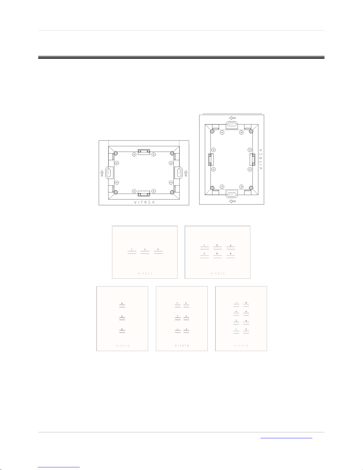
The VTouch Plus keypad can be installed horizontally or vertically. The keypad should be positioned
in the wall mounting box as shown in the figure below. Note that in a vertical installation, the
VITREA logo is to the right of the keypad.
Figure 1: Horizontal vs. Vertical Installation
Figure 2: Horizontal and Vertical Keypad Options
Page 6
VTouch-Plus Configuration Tool User Guide
VITREA Smart Home Technologies | T: +972.3.5474746 | F: +972.3.5474738 | vitrea-sh.com | [email protected]
Page 6 of 27
Floating or Flush Mount Installation
VTouch Plus keypad installation can be either flush-mount or floating. In both installations, a
background blue light further enhances the aesthetic design of the product as well as serving a
functional purpose of illuminating the keypad in the dark.
For a floating installation, do the following:
1. Place the keypad into the wall mounting box.
2. Use two screws to fasten the keypad in place.
3. Attach the glass panel to the keypad.
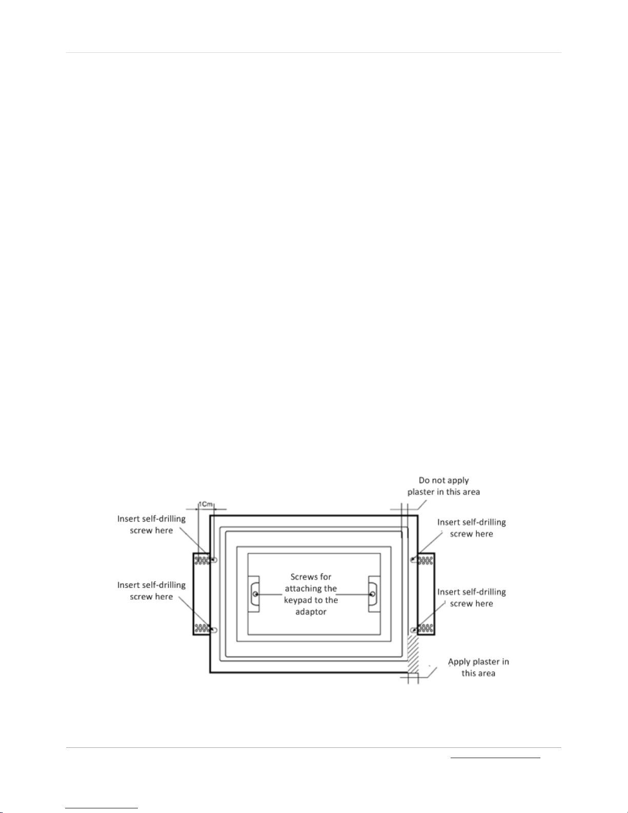
For a flush-mount installation of the keypad that creates a single smooth unit with the wall, use the
Vitrea adaptor for an easy plug & play installation. The glass panel is installed flush with the wall,
with a 1 mm line between the wall and the glass.
Caution: The adaptor is made from strong, quality Gypsum material. Handle it carefully to prevent
chips to its corners and sides. Read the safety instructions carefully before installing.
To install the adaptor for a drywall installation:
1. Turn off the electricity from the main fuse panel.
2. Determine precisely where you want to install the VTouch keypad on the drywall.
3. Use the attached diagram to mark the cutting lines of the rectangular area where the adaptor
will be inserted. Use a level to ensure that your lines are completely horizontal.
4. Using a utility knife (x-Acto blade) and a metal ruler, cut the drywall according to your reference
marks.
5. Insert the drywall adaptor into the opening in the wall and fasten it using the four included self-
drilling screws (two on each side). Use a level to position the adaptor as horizontally as possible.
Complete the installation process by plastering and painting the area around the adaptor.
Page 7
User Guide VTouch-Plus Configuration Tool
VITREA Smart Home Technologies | T: +972.3.5474746 | F: +972.3.5474738 | vitrea-sh.com | [email protected]
Page 7 of 27
Positioning Adjacent Keypads
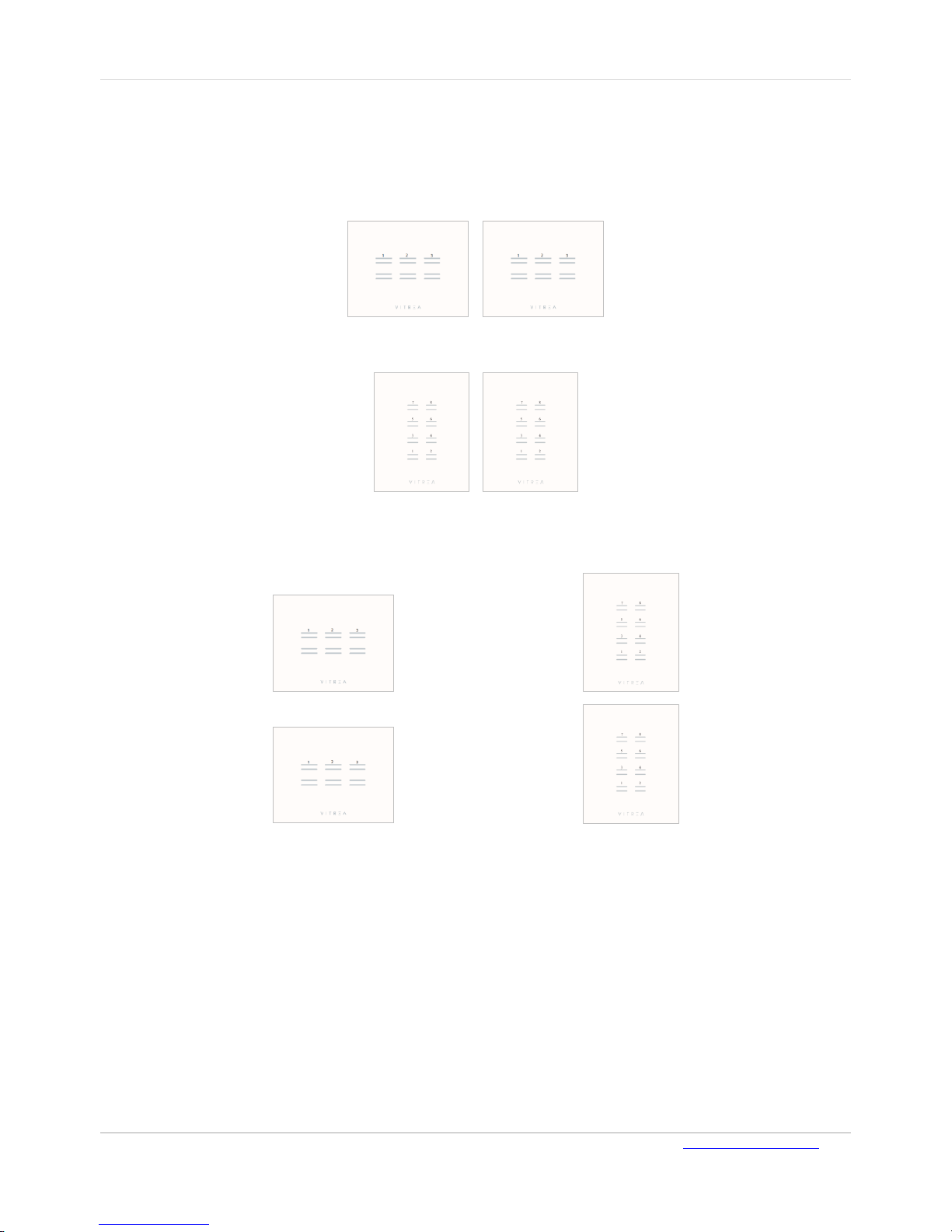
The following tables specify the recommended distances between the centers of the wall mounting
boxes when installing adjacent VTouch keypads (side-by-side or one above the other).
The recommended distances depend on the dimensions of the glass panels:
Figure 3: Side-by-Side Installation of Horizontal Glass Panels
Figure 4: Side by Side Installation of Vertical Glass Panels
Figure 5: Installation of Horizontal and Vertical Glass Panels One Above the Other
Page 8

VTouch-Plus Configuration Tool User Guide
VITREA Smart Home Technologies | T: +972.3.5474746 | F: +972.3.5474738 | vitrea-sh.com | [email protected]
Page 8 of 27
Recommended Distance for Side-by-Side Keypads
Keypad A
Keypad B
Recommended distance
between glass panels (cm)
Horizontal distance between
centers of mounting boxes (cm)
Vertical
Vertical
2
12
Horizontal
Horizontal
2
14
Recommended Distance for Keypads One above the Other
Keypad A
Keypad B
Recommended distance
between glass panels
(cm)
Vertical distance between centers
of the mounting boxes (cm)
Vertical
Vertical 2 14
Horizontal
Horizontal 2 12
If the recommended distance between glass panels is not followed, the distance between the centers
of the wall mount boxes should be adjusted accordingly.
For best results (esthetically and functionally) it is recommended to place the keypads at a height of
120 cm from the floor.
Page 9
User Guide VTouch-Plus Configuration Tool
VITREA Smart Home Technologies | T: +972.3.5474746 | F: +972.3.5474738 | vitrea-sh.com | [email protected]
Page 9 of 27
CHAPTER 2 VTOUCH PLUS - INSTALLATION & WIRING
Overview
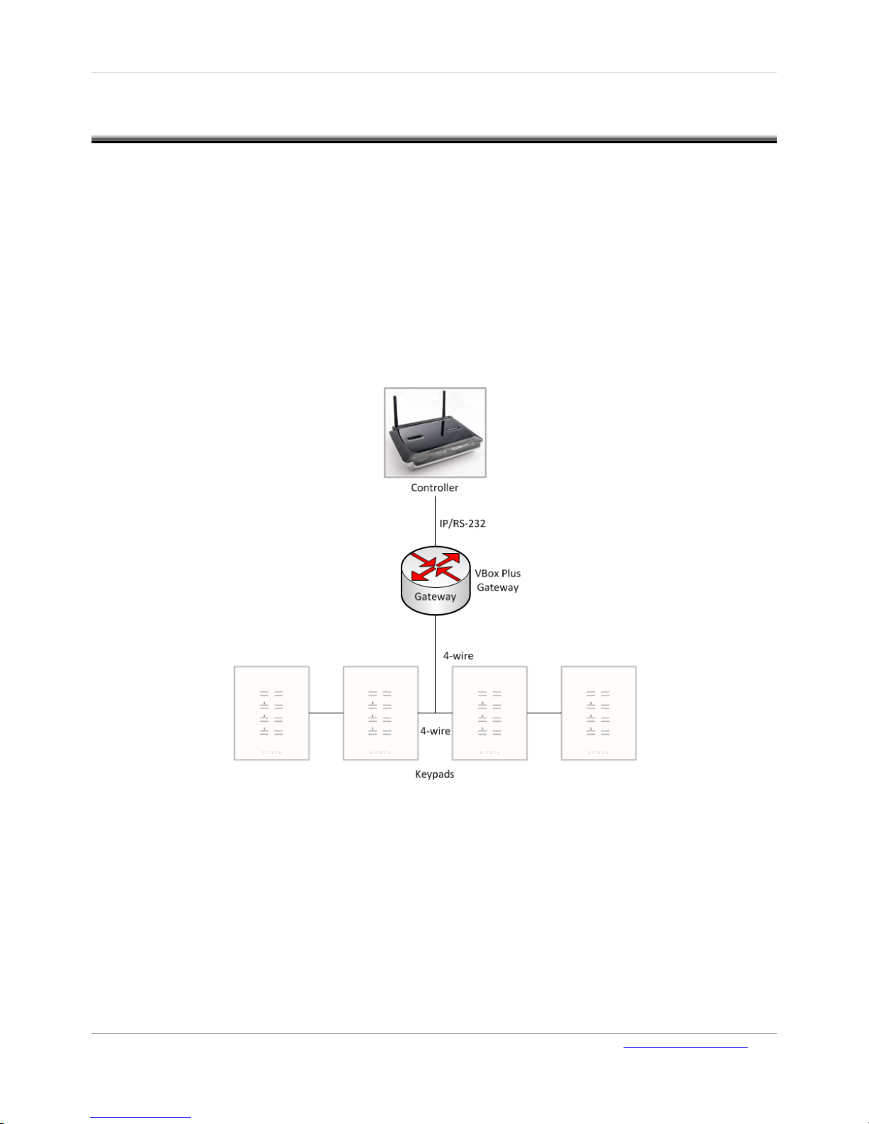
The VBOX-Plus gateway (VP gateway) is connected to a third-party Smart Home Processor
Controller (Host) via an RS-232 cable or an IP connection, and to the VTouch Plus keypads via a 4wire bus (two wires for RS-485 data communication and two for 24 VDC power supply).
The communication protocol between the VP gateway and the third-party Smart Home Processor
Controller is available for driver developers.
The communication protocol between the VP Gateway and the VTouch Plus keypads is Vitrea’s
proprietary protocol and runs on the RS-485 physical layer. Up to fifty keypads can be connected to
each VP gateway. For installations with more than 50 keypads, an additional VP gateway should be
added.
Figure 6: 4-Wire Bus Connectivity
Page 10
VTouch-Plus Configuration Tool User Guide
VITREA Smart Home Technologies | T: +972.3.5474746 | F: +972.3.5474738 | vitrea-sh.com | [email protected]
Page 10 of 27
Description of the VTouch Plus (VP) Gateway
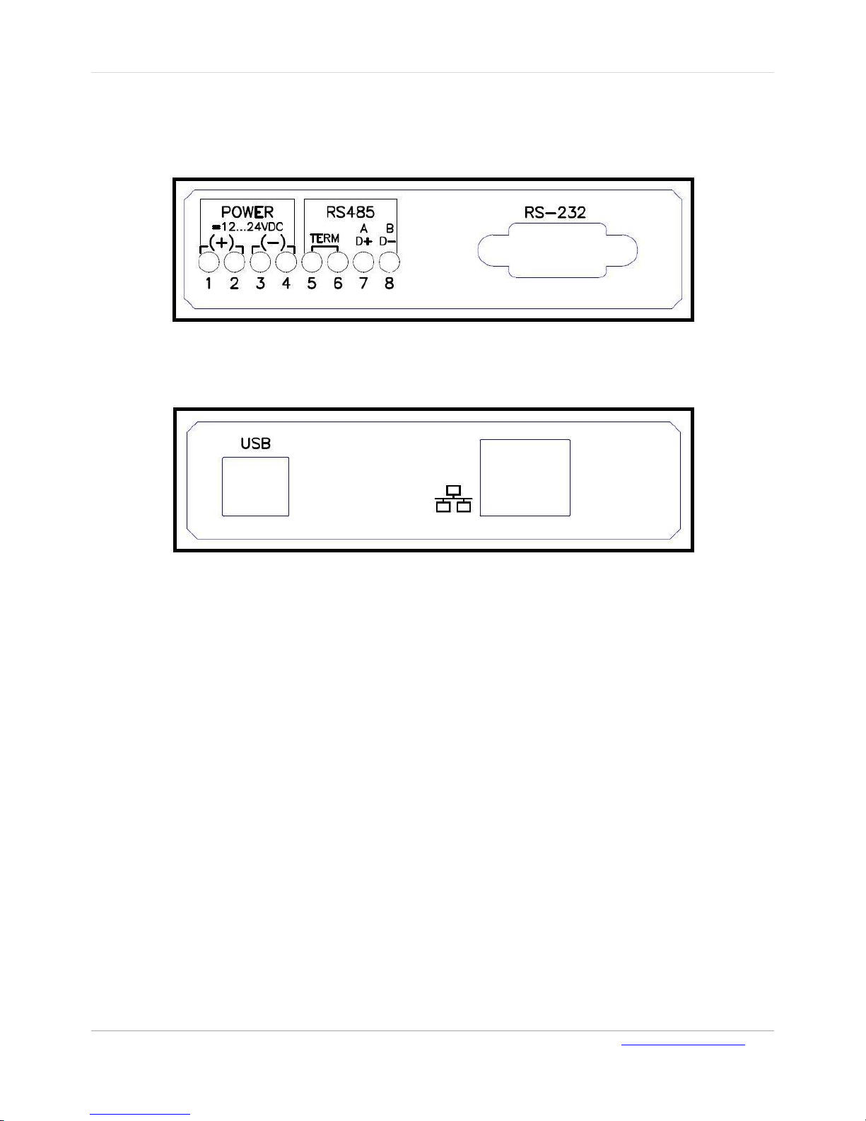
The VP Gateway manages the communication between the VTouch Plus keypads and the Host. The
VP Gateway is DIN mountable.
Figure 7: VP Gateway – Front Panel
Figure 8: VP Gateway – Back Panel
Page 11

User Guide VTouch-Plus Configuration Tool
VITREA Smart Home Technologies | T: +972.3.5474746 | F: +972.3.5474738 | vitrea-sh.com | [email protected]
Page 11 of 27
The following describes the VP Gateway connections:
USB Port – The PC is connected to the USB port to configure the keypads via a utility software
or terminal emulation program. The following functions are available via the USB port:
Assign addresses to the keypads
Add/delete/replace keypads in the system
Set the Button-Type for each button according to application requirements
Set the intensity level of the surrounding blue LEDs
Set the timing parameters of each keypad for “short-press” and “double-press”
Give a name/location to each keypad in the system
Test communication with each keypad
Select RS-232 or IP connectivity to the Host
Set the IP parameters.
RS-232 Port – The VP Gateway can connect to the Host via this port. The connector is a DB-9
female and only 3 wires are used for communication: Pin 2 is the TX of the VP Gateway, Pin 3 is
the RX of the VP Gateway, and Pin 5 is GND.
Pin 2 connects to the RX of the Host.
Pin 3 connects to the TX of the Host.
Pin 5 connects to the GND of the Host.
The communication parameters are: 9600, N, 1.
Note: When the VP Gateway is configured to communicate with the Host via the RS-232 port,
the IP port is disabled.
IP Port - The VP Gateway can connect to the Host via this port.
Note: When the VP Gateway is configured to communicate with the Host via the IP port, the RS-
232 port is disabled.
RS-485 Port – The VP Gateway communicates with the VTouch Plus keypads via this port. Pins
A and B are connected via the 4-wire bus to Pins A and B of each keypad (A to A and B to B).
Term – When a termination is required, a jumper is connected to the Term connector. An
internal 120 Ohm resistor will terminate the communication line.
24 VDC – This is connected to the (+) and (-) terminals of the 24 VDC power supply and to the
two power wires of the 4-wire bus.
LED Indications – There are three LEDs on the top panel of the VP Gateway:
Power– Indicates that the 24 VDC is connected.
Error – Lights up when there is a communication problem between the VP Gateway and at
least one of the VTouch Plus keypads.
Data – Blinks when there is communication between the VP Gateway and the Host.
Page 12

VTouch-Plus Configuration Tool User Guide
VITREA Smart Home Technologies | T: +972.3.5474746 | F: +972.3.5474738 | vitrea-sh.com | [email protected]
Page 12 of 27
Step by Step System Installation & Configuration
1. Wiring the 4-Wire Bus
The connection between the VP Gateway and the VTouch Plus keypads is achieved via a 4-wire
bus. Two wires are for the RS-485 data communication between the VP Gateway and the VTouch
Plus keypads, and two wires are for the 24 VDC power supply for the VP Gateway and the
VTouch Plus keypads.
The optimal configuration for the RS-485 bus is the daisy-chain connection from keypad 1 to
keypad 2 to keypad 3, and so on to keypad n. The data cable should be a twisted-pair.??
a. Connect the 4-wire bus cable to the back of the keypads as follows:
i. Connect the two power wires to the (+) and (-) of the 24 VDC of all the keypads.
ii. Connect the two data wires to the A and B data connections of all the keypads.
b. Connect the 4-wire bus cables to the VP Gateway as follows:
i. Connect the two power wires to the (+) and (-).
ii. Connect the two data wires to the A and B data connections.
c. Connect the 24 VDC power supply to the (+) and (-) connections at the VP Gateway.
Note: The two (+) connections of VP Gateway are internally connected, and so are the two (-)
connections of VP Gateway.
d. Connect the power supply
2. Connecting the Configuration Tool Software to the VP Gateway
a. Connect a PC to the USB port of the VP Gateway.
b. Configure the system. See "Configuring the System" in the "Using the Configuration
Software" chapter for information.
c. Make sure the Type of each button fits your system design/requirements.
d. Disconnect the PC and the USB cable.
3. Connecting the VP Gateway to the Smart Home Processor Controller
The VP Gateway and Host are connected either by an RS-232 cable that is connected to a DB-9
connector, or by an IP connection via the RJ-45 Connector.
a. Connect the RS-232 cable or IP cable between the Host and VP Gateway. Connect the VP
Gateway to the Host using the RS-232 port. The connector is a DB-9 female and only 3 wires
are used for communication: Pin 2 is the TX of the VP Gateway, Pin 3 is the RX of the VP
Gateway, and Pin 5 is GND.
Connect Pin 2 to the RX of the Host.
Connect Pin 3 to the TX of the Host.
Connect Pin 5 to the GND of the Host.
The communication parameters are: 9600,N,1.
Note: The Host and Gateway are connected using the RS-232 cable only after configuration is
completed and the PC is disconnected from the USB port.
b. Install the correct driver in the third-party Smart Home Controller (such as Crestron or RTI).
c. Build scenarios while using input from VTouch Plus keypads.
Page 13

User Guide VTouch-Plus Configuration Tool
VITREA Smart Home Technologies | T: +972.3.5474746 | F: +972.3.5474738 | vitrea-sh.com | [email protected]
Page 13 of 27
CHAPTER 3 USING THE CONFIGURATION SOFTWARE
Overview
Connect a PC to the USB port to configure the keypads via a utility software or terminal emulation
program. The configuration software enables you to perform:
System configuration
Keypad configuration
Host connection setup
System Requirements
Operating System: MS Windows XP SP2 or Windows 7 with Microsoft.Net Framework 2 installed.
Installing the Configuration Tool
To install the configuration tool:
1. Download the “VBOX-Plus_Configuration_Tool.zip” file from the following link: http://vitrea-
sh.com/wp-content/uploads/2013/10/VBOX-Plus-Configuration-Tool.zip, and then unzip it to the
required local directory, taking careful note of the directory's location. Create a shortcut on your
PC desktop to the VBOX-Plus Configuration Tool .exe file.
2. Connect the USB cable between your computer and the VBOX-Plus Gateway. The FTDI USB-to-
Serial driver begins installing.
3. If installation fails, this is likely because your computer cannot automatically find the driver
package in its local directories. Connect your computer to the Internet or download the FTDI
USB-to-Serial package to your computer from the official FTDI WEB site.
Note: When the USB cable is connected between your computer and the VBOX-Plus Gateway,
communication between the Host and the VBOX-Plus Gateway, via RS-232 or Ethernet
connection, is terminated. When configuration is complete, disconnect the USB cable,
to enable the VBOX-Plus Gateway to resume communication with an external host.
Page 14
VTouch-Plus Configuration Tool User Guide
VITREA Smart Home Technologies | T: +972.3.5474746 | F: +972.3.5474738 | vitrea-sh.com | [email protected]
Page 14 of 27
Connecting the Configuration Tool Software to the VBOX-Plus Gateway
To connect to the VBOX-Plus gateway:
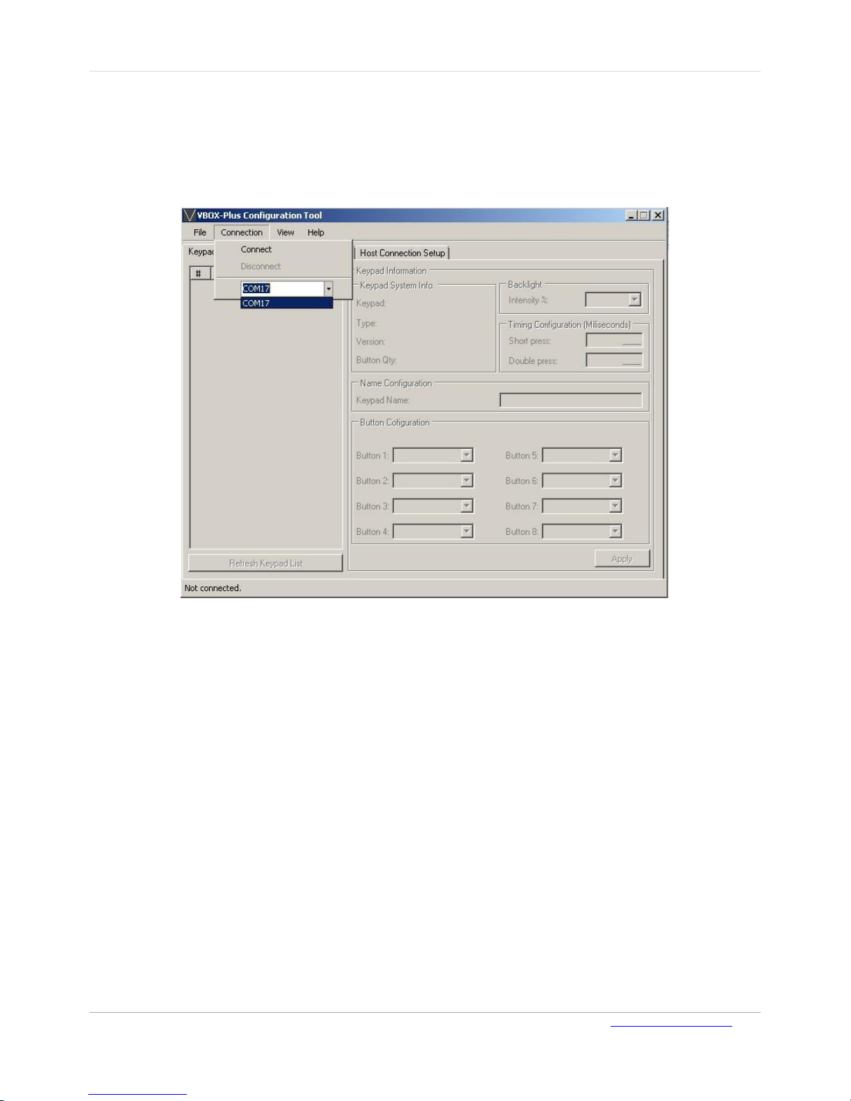
1. Click the shortcut on your desktop to open the VBOX-Plus Configuration Tool. The status bar
displays a “Not connected” status.
Figure 9: Connection Menu
2. On the Connection menu, select the COM port from a list of available COM ports and click Connect.
After a few seconds the program connects to the VBOX-Plus Gateway and displays a list of existing
keypads.
Note: If the USB cable or power to the VBOX-Plus Gateway is disconnected during operation,
reconnect to the COM port manually.
Configuring the System
The following system configuration operations can be performed:
VBOX-Plus Gateway, one or all keypads, or the entire system can be set to factory default
settings
VBOX-Plus Gateway, or one or all of keypads can be reset
New keypads can be added
Existing keypads can be deleted or replaced
Already programmed keypads can be automatically registered into VBOX-Plus Gateway
Note: Before configuring a new system, it is recommended to reset the system to the factory
default.
Page 15
User Guide VTouch-Plus Configuration Tool
VITREA Smart Home Technologies | T: +972.3.5474746 | F: +972.3.5474738 | vitrea-sh.com | [email protected]
Page 15 of 27
Resetting to Factory Default
To reset to the factory default:
1. On the System Configuration page, click Full System Factory Reset.
2. Confirm your choice on the dialog box that opens and then wait about 10 seconds until the
progress bar indicates the operation is complete.
Registering New Keypads
To register new keypads:
1. Connect the Gateway and keypads to the four-wire network. See "Connecting between the VP
Gateway and VTouch Plus Keypads"
2. Reset all keypads to factory default. See "Resetting to Factory Default" in this chapter for
information.
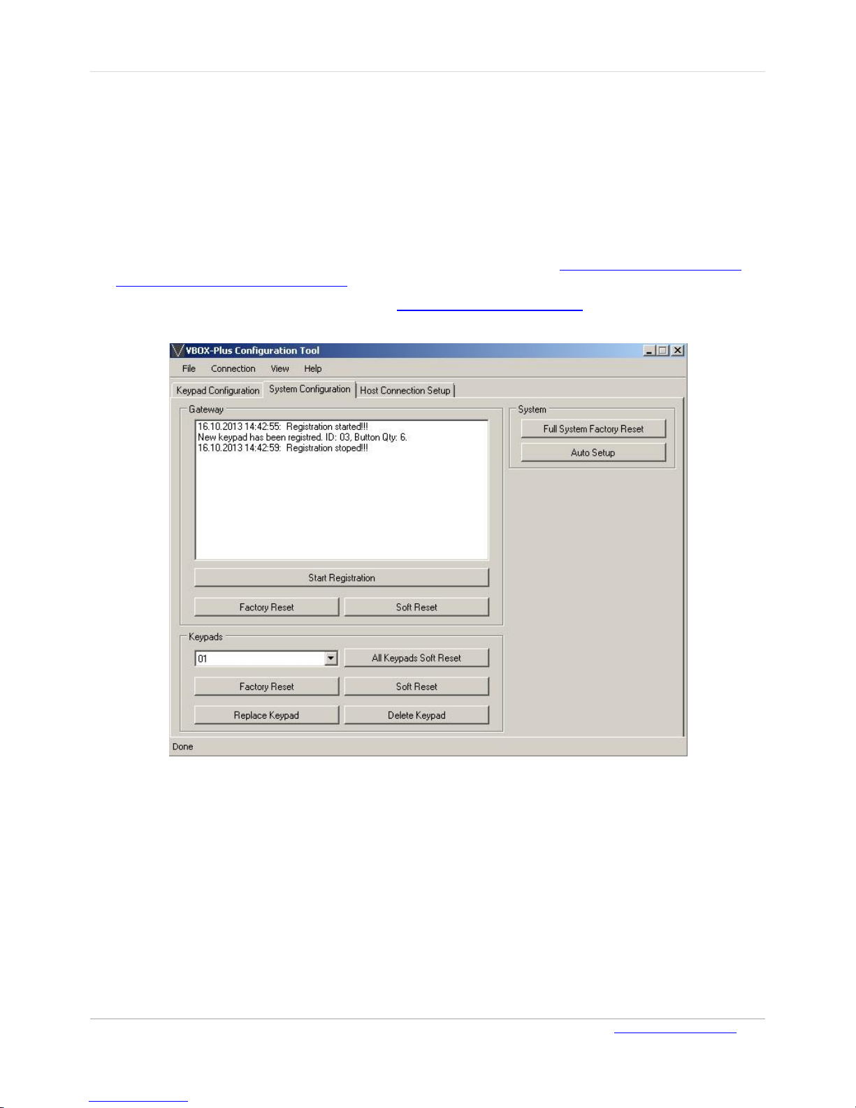
Figure 10: System Configuration Page
3. On the System Configuration page, click Start Registration.
4. On all keypads, which are ready to be registered in the system, all the orange LED’s will begin
blinking. Touch any button on a keypad to add it to the system.
5. Repeat this process one keypad at a time until all the desired keypads are registered (and have
stopped blinking). The keypads are numbered in the sequence they have been touched.
Registration information for each added keypad, including keypad ID and number of supported
keypads, is displayed in the Gateway section on the open dialog.
6. If you want to stop or pause the keypad registration process, click Stop Registration.
Note: Any new keypad registered with a gateway will receive the next available keypad number,
e.g. if the last keypad last ID was 05, then the next added keypad will receive the ID 06.
Page 16

VTouch-Plus Configuration Tool User Guide
VITREA Smart Home Technologies | T: +972.3.5474746 | F: +972.3.5474738 | vitrea-sh.com | [email protected]
Page 16 of 27
Replacing a Keypad
If the keypad that is being replaced is to be assigned an ID that was previously assigned to a
different keypad, the “Replace Keypad” function should be used.
To replace a keypad:
1. Disconnect the old keypad from the four-wire network and connect the new one.
2. Manually reset the keypad to factory default. See "Resetting to Factory Default" in this chapter
for information.
3. In the Keypads section of the open dialog box, select the ID of the keypad to be replaced and
click Replace Keypad.
4. All the orange LED’s of the new keypad will begin blinking. Touch any of the buttons on the new
keypad to add it to the system with the selected ID number.
Replacing a VBOX-Plus Gateway
If an existing VBOX-Plus gateway needs to be replaced, the “Auto Setup” function should be used.
Auto Setup enables you to replace a VBOX-Plus Gateway with a new one in an existing network with
already configured keypads. This function automatically reads the information from all keypads
connected to the system and configures the VBOX-Plus Gateway accordingly.
Important: Auto Setup also resets the configuration of the Host interface to the factory default.
To replace the VBOX-Plus gateway:
1. Disconnect the old VP gateway from the four-wire network and connect the new one.
2. Connect the PC with a USB cable to the USB port of the new VP gateway.
3. Click Auto Setup. This function automatically reads the information from all keypads connected
to the system and configures the new VBOX-Plus Gateway accordingly.
4. Configure the Host interface (RS-232 or IP) accordingly for communication with the Host.
Page 17
User Guide VTouch-Plus Configuration Tool
VITREA Smart Home Technologies | T: +972.3.5474746 | F: +972.3.5474738 | vitrea-sh.com | [email protected]
Page 17 of 27
Configuring the Keypad
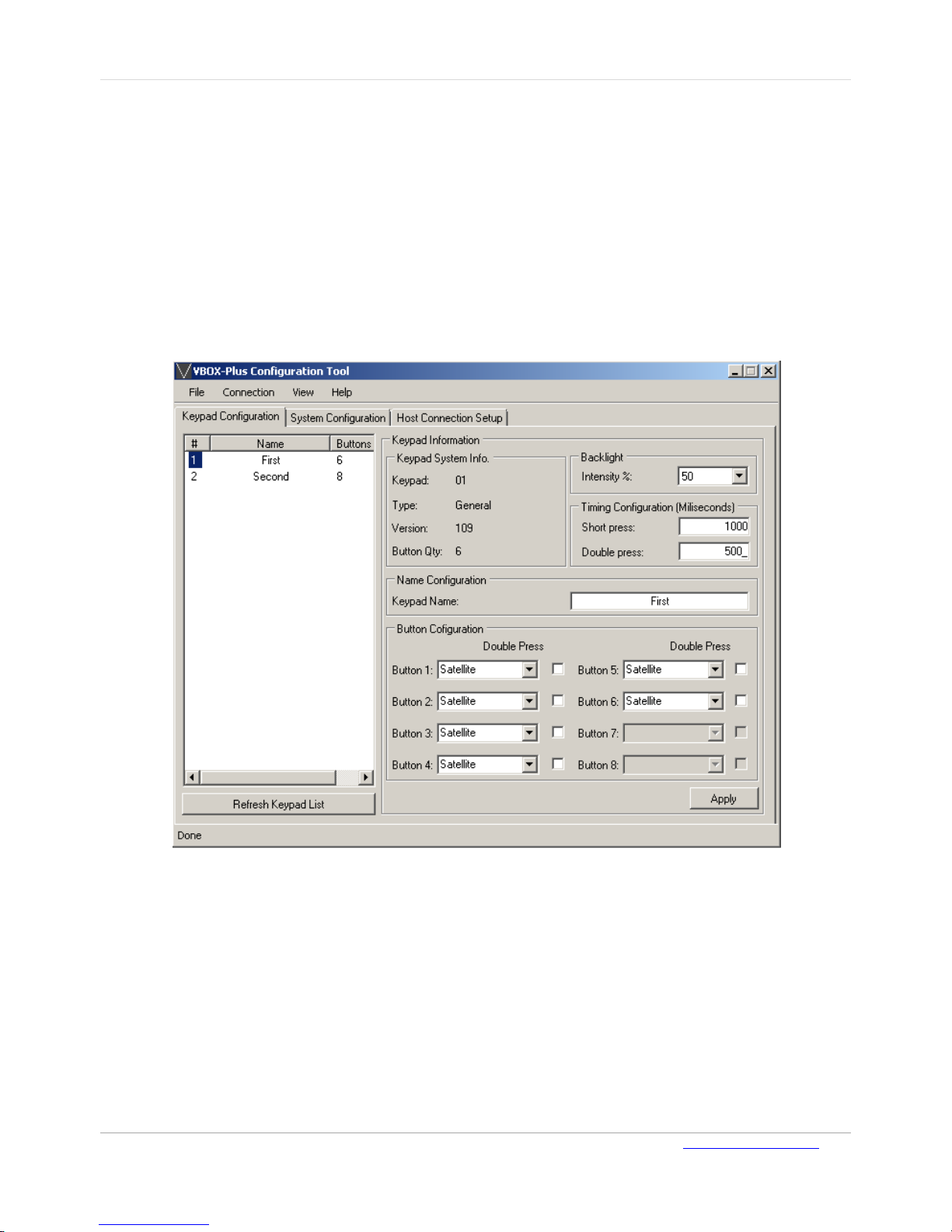
The following keypad settings can be configured via the Keypad Configuration page:
Keypad buttons can be configured as Toggle, Satellite, Push Button or Disabled
Enable/disable Double Press function for each button
Timing for Short Press and Double Press
Adjusting the blue background light intensity
Keypad name
Keypad type (Standard or Lutron) and firmware version details are also displayed on this page.
Figure 11: Keypad Configuration Page
To configure a keypad:
1. On the Keypad Configuration page, select the required keypad from the list of keypads.
2. Modify the keypad settings as required, and then click Apply to save the changes.
Note: The list of keypads can be updated at any point by clicking Refresh Keypad List.
Page 18
VTouch-Plus Configuration Tool User Guide
VITREA Smart Home Technologies | T: +972.3.5474746 | F: +972.3.5474738 | vitrea-sh.com | [email protected]
Page 18 of 27
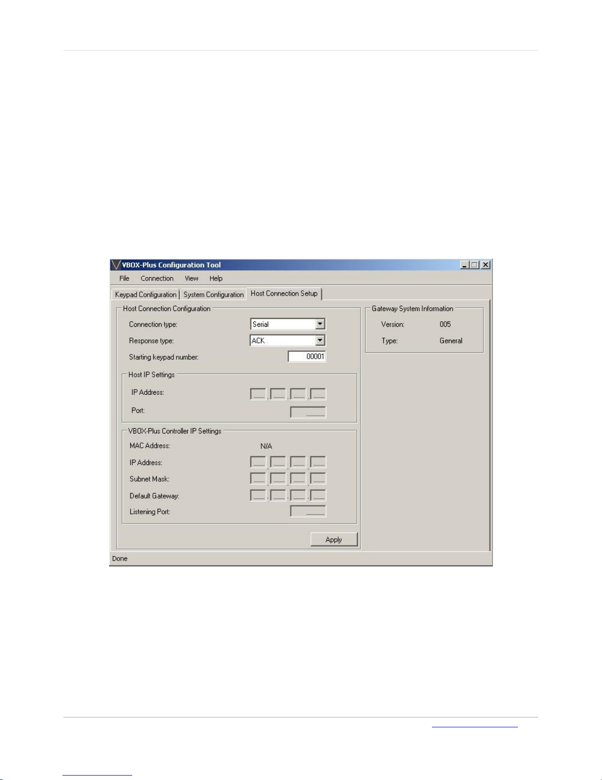
Host Connection Setup
The following host connection settings can be configured on the Host Connection Setup page:
Host connection type: Serial via RS-232 (default), TCP Client or Server via Ethernet
Response to host commands type
Starting keypad number
IP address, Subnet Mask and Default Gateway IP Address of the VBOX-Plus Gateway
TCP/IP Port
IP address of remote host (for TCP Client mode)
Additional information is also provided on this page about the VBOX-Plus Gateway including, NIC
MAC Address, FW version and type.
Figure 12: Host Connection Setup Page
To configure the host connection:
On the Host Connection Setup page, make the required changes, and click Apply.
Note: The keypads are numbered sequentially from 1 to 50 through the registration process. All
communication between the Gateway and the keypads uses this numbering system. The
Starting keypad number field is only used for Gateway-Host communication. For example,
if the Starting keypad number entered is 1000, then the host must use Keypad number 1001
to refer to Keypad 1.
Page 19
User Guide VTouch-Plus Configuration Tool
VITREA Smart Home Technologies | T: +972.3.5474746 | F: +972.3.5474738 | vitrea-sh.com | [email protected]
Page 19 of 27
Configuring a Host as Server
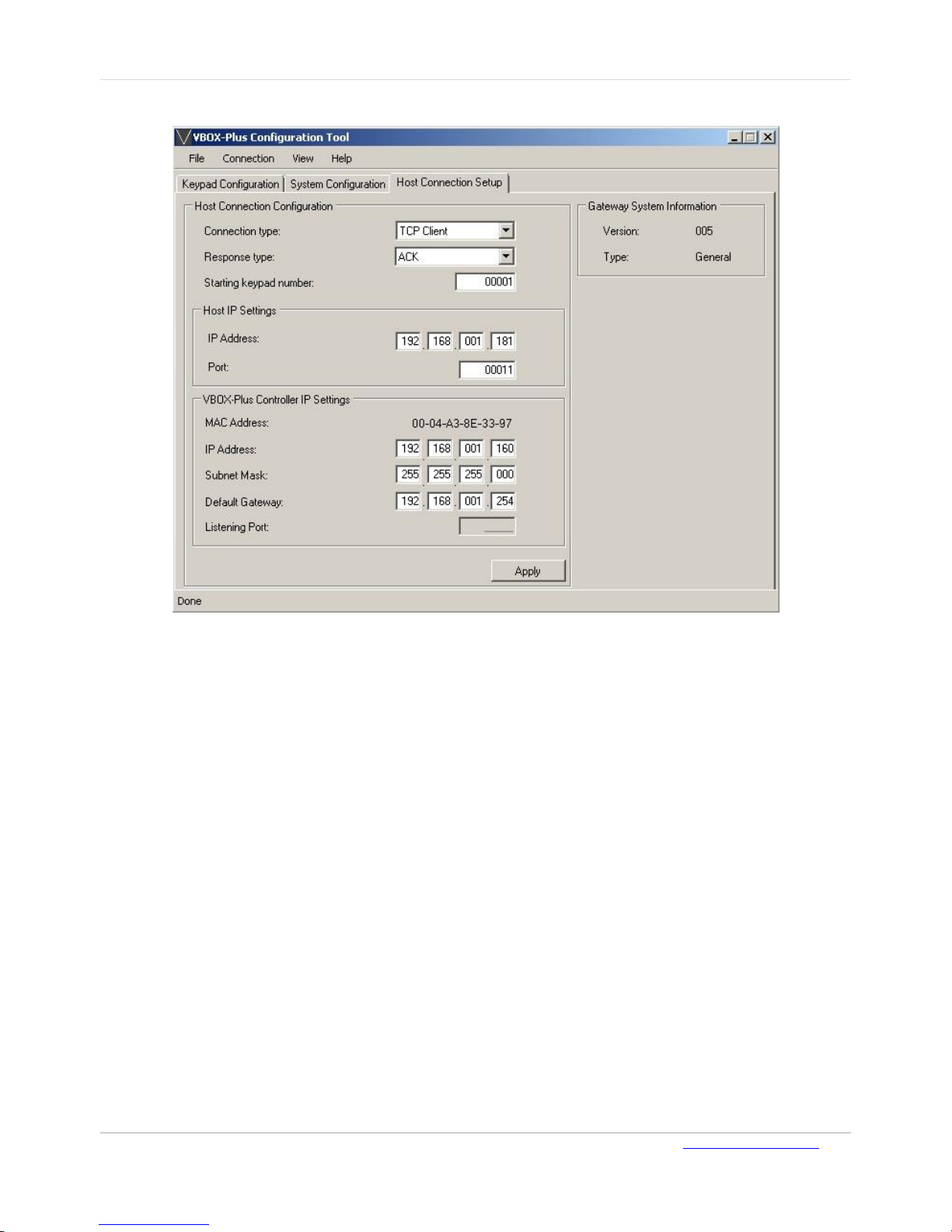
Figure 13: Host Connection Setup - 1
To configure the VBOX-Plus Gateway to work with an external Host via Ethernet connection as a
TCP/IP Client (The Host functions as a server):
1. On the Host Connection Setup age, in the Connection Type field, select TCP Client.
2. In the Host IP Settings section, type the IP address and TCP/IP Port of the external host
3. In the VBOX-Plus Controller IP Settings, type the IP address, network Subnet Mask and
Default Gateway of the VBOX-Plus Gateway
4. Click Apply to save the configuration.
Page 20
VTouch-Plus Configuration Tool User Guide
VITREA Smart Home Technologies | T: +972.3.5474746 | F: +972.3.5474738 | vitrea-sh.com | [email protected]
Page 20 of 27
Configuring a Host as Client
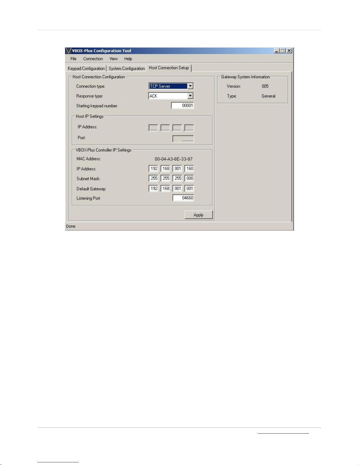
Figure 14: Host Connection Setup - 2
To configure the VBOX-Plus Gateway to work with an external host via Ethernet connection as a
TCP/IP Server (The host functions as a client):
1. On the Host Connection Setup age, in the Connection Type field, select TCP Server.
2. In the VBOX-Plus Controller IP Settings, type the IP address, network Subnet Mask, Default
Gateway, and Listening Port of the VBOX-Plus Gateway.
3. Click Apply to save the configuration.
Page 21
User Guide VTouch-Plus Configuration Tool
VITREA Smart Home Technologies | T: +972.3.5474746 | F: +972.3.5474738 | vitrea-sh.com | [email protected]
Page 21 of 27
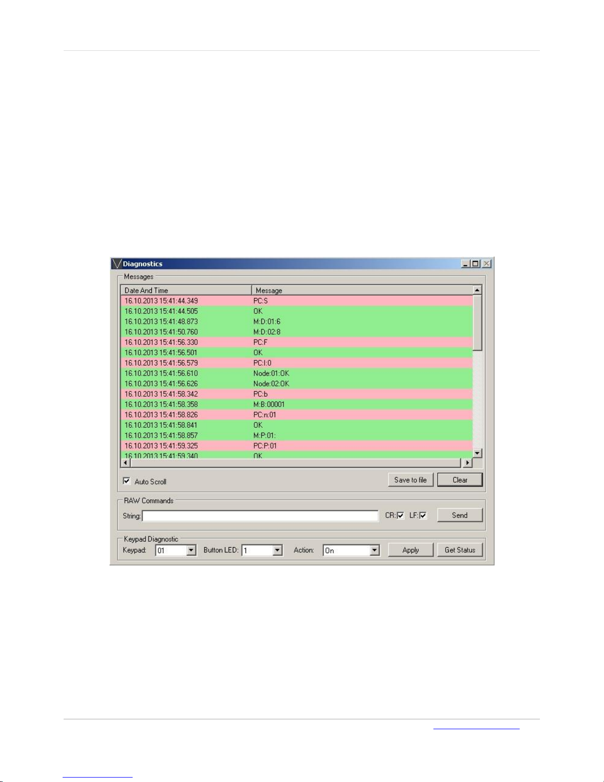
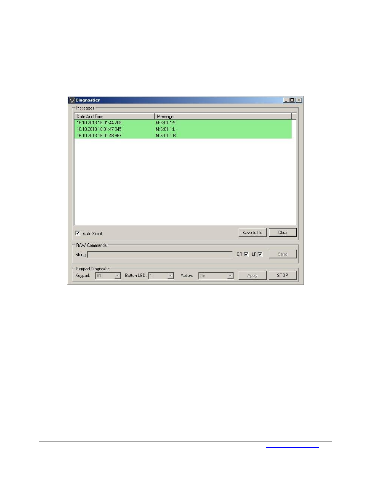
Diagnostics Window
The following operations are performed from the Diagnostics page:
Monitor the messages passing between the program and VBOX-Plus Gateway during the
configuration process
Send the commands to the VBOX-Plus Gateway manually
Change the status of a single or of all LED’s on any selected keypad
Obtain the touch status of keys (buttons) on any selected keypad
Save the diagnostic messages to a computer file
The Diagnostics page is opened from the View menu.
Figure 15: Diagnostics Page - 1
Page 22
VTouch-Plus Configuration Tool User Guide
VITREA Smart Home Technologies | T: +972.3.5474746 | F: +972.3.5474738 | vitrea-sh.com | [email protected]
Page 22 of 27
To save the messages window content to a computer file:
On the Diagnostics page, click Save to file. The file is saved with a date/time stamp name in the
program's working folder.
To obtain the touch status of keys (buttons) on any selected keypad:
1. In the Keypad field, enter the ID of the required Keypad.
2. Click Get Status.
Figure 16: Diagnostics Page - 2
3. Click STOP to cancel the reporting process.
Page 23
User Guide VTouch-Plus Configuration Tool
VITREA Smart Home Technologies | T: +972.3.5474746 | F: +972.3.5474738 | vitrea-sh.com | [email protected]
Page 23 of 27
CHAPTER 4 PROGRAMMING THE KEYPAD
Adjusting the Intensity of the Background Blue LEDs
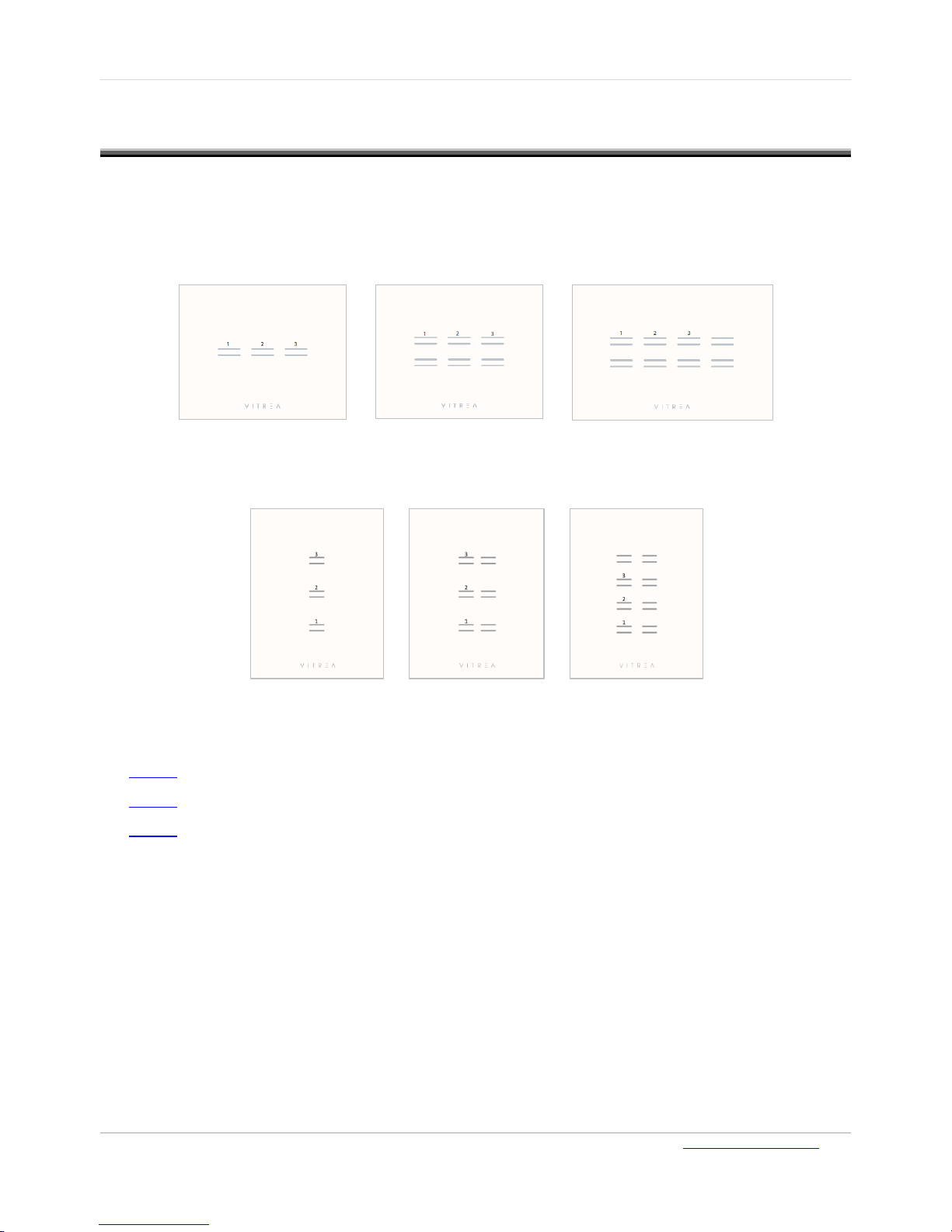
The background blue LEDs' intensity can be adjusted using the three programming buttons. The
figures below illustrate the 1,2 and 3 buttons for the different keypad options.
Figure 17: 3, 6, 8 Buttons – Horizontal Installation
Figure 18: 3, 6, 8 Buttons – Vertical Installation
Programming involves three steps:
Step 1: Entrance into programming mode
Step 2: Programming intensity level of the blue LEDs
Step 3: Exiting programming mode
Step 1: Entering programming mode
To enter programming mode:
1. Press and hold buttons 1 and 2 simultaneously for at least two seconds.
2. Press button 1 once (1x) without holding.
3. Press button 2 twice (2x) without holding.
4. Press button 3 three times (3x) without holding.
5. Press button 2 twice (2x) without holding.
6. Press button 1 once (1x) without holding.
Page 24

VTouch-Plus Configuration Tool User Guide
VITREA Smart Home Technologies | T: +972.3.5474746 | F: +972.3.5474738 | vitrea-sh.com | [email protected]
Page 24 of 27
Step 2: Programming - Adjusting the background blue LEDs
There are five intensity levels – from ‘off’ to ‘maximum’ (1 to 5).
To decrease blue LED intensity:
Press button 1 repeatedly until the desired intensity level is reached.
To increase blue LED intensity:
Press button 3 repeatedly until the desired intensity level is reached.
Step 3: Exiting programming mode
The keypad will automatically exit the programming mode if no button is pressed for 10 seconds or
more. Programmed data is saved on nonvolatile memory and remains in memory even when
electricity is turned off.
Resetting the Keypad to Factory Default
The keypad is reset to factory default by programming the keys as described below or via the
configuration software utility. The factory default parameters are as follows:
Parameter
Value
Address
No Address
Button Type
Satellite
Keypad Name
None
Short Press Time
1000 ms
Double Press Time
500 ms
The keypad is programmed using buttons 1, 2 and 3 on the keypad. Figure 17 and Figure 18 above
indicate the location of these buttons on different keypads.
To reset the keypad, do the following:
1. Press and hold buttons 2 and 3 simultaneously for at least two seconds.
2. Press button 1 three times (3x) without holding.
3. Press button 2 twice (2x) without holding.
4. Press button 3 once (1x) without holding.
5. Press button 2 twice (2x) without holding.
6. Press button 1 three times (3x) without holding.
Page 25

User Guide VTouch-Plus Configuration Tool
VITREA Smart Home Technologies | T: +972.3.5474746 | F: +972.3.5474738 | vitrea-sh.com | [email protected]
Page 25 of 27
SPECIFICATIONS
VBOX-Plus Gateway Specifications
Specification
Description
Power Supply
24 VDC, 100mA (see note below)
RS-232 Port
Bi-directional, DB-9 connection
RS-485 Port
Bi-directional
Ethernet Port
10 Base-T
USB Port
One, type B
Mounting
DIN
Dimensions
10 (W) x 9(H) x 4(D) cm
VTouch-Plus Keypad Specifications
Specification
Description
Power Supply
12-24 VDC, 10mA
RS-485 Connection
Bi-directional
Fits into Wall Mounting Box
Italian Module 3
Background Light
Blue, adjustable intensity
Button LED
Orange
Power Consumption
The 24 VDC power supply delivers power to the keypads via two wires of the 4-wire bus.
Maximum current consumption per keypad: 10 mA
Maximum current consumption of VP Gateway: 100 mA.
Total maximum current consumption: (50 (keypads) * 10 mA) + 100 mA for the VP Gateway =
600 mA.
Page 26
VTouch-Plus Configuration Tool User Guide
VITREA Smart Home Technologies | T: +972.3.5474746 | F: +972.3.5474738 | vitrea-sh.com | [email protected]
Page 26 of 27
FEDERAL COMMUNICATIONS COMMISION NOTICE
This equipment has been tested and found to comply with the limits for a Class B digital device,
pursuant to part 15 of the FCC Rules. These limits are designed to provide reasonable protection
against harmful interference in a residential installation. This equipment generates, uses and can
radiate radio frequency energy and, if not installed and used in accordance with the instructions,
may cause harmful interference to radio communications. However, there is no guarantee that
interference will not occur in a particular installation. If this equipment does cause harmful
interference to radio or television reception, which can be determined by turning the equipment off
and on, the user is encouraged to try to correct the interference by one or more of the following
measures:
Reorient or relocate the receiving antenna.
Increase the separation between the equipment and receiver.
Connect the equipment into an outlet on a circuit different from that to which the receiver is
connected.
Consult the dealer or an experienced radio/TV technician for help.
This device complies with Part 15 of the FCC Rules. Operation is subject to the following two
conditions:
This device may not cause harmful interference.
This device must accept any interference received, including interference that may cause
undesired operation.
Page 27

User Guide VTouch-Plus Configuration Tool
VITREA Smart Home Technologies | T: +972.3.5474746 | F: +972.3.5474738 | vitrea-sh.com | [email protected]
Page 27 of 27
LIMITED WARRANTY
Vitrea Smart Home Technologies warrants its products for a period of 18 months from the date of
purchase from Vitrea or an authorized Vitrea distributor. This warranty may be enforced by the
original purchaser and subsequent owners during the warranty period, so long as the original dated
sales receipt or other proof of warranty coverage is presented when warranty service is required.
Except as specified below, this warranty covers all defects in material and workmanship in this
product. The following are not covered by the warranty:
Damage resulting from:
Accident, misuse, abuse, or neglect.
Failure to follow instructions contained in this guide.
Repair or attempted repair by anyone other than Vitrea.
Failure to perform recommended periodic maintenance.
Causes other than product defects, including lack of skill, competence or experience of user.
Shipment of this product (claims must be made to the carrier).
Being altered or which the serial number has been defaced, modified, or removed.
Vitrea is not liable for any damages caused by its products or for the failure of its products to
perform, including any lost profits, lost savings, incidental damages, or consequential damages.
Vitrea is not liable for damages based upon inconvenience, loss of use of the product, loss of time,
interrupted operation, commercial loss, any claim made by a third party or made by you for a third
party.
Vitrea's liability for any defective product is limited to repair or replacement of the product, at our
option.
If your VTouch Plus device needs service, please contact Vitrea by telephone, fax, or email for return
information. Please do not return products to Vitrea without return authorization.
 Loading...