

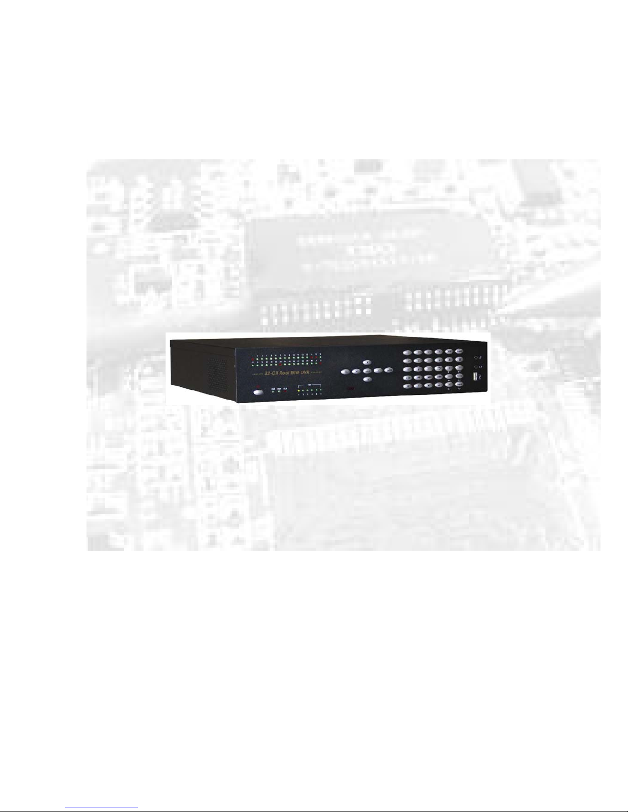
24/32 channel REALTIME DVR
User Instruction Manual
VERSION 1.0
Before attempting to connect or operate this product, please read these instructions carefully and
save this manual for future use.
Warning
¾ This apparatus must be earthed.
¾ Apparatus shall be connected to a mains socket outlet with a protective earthing connection.
¾ The mains plug or an appliance coupler shall remain readily operable.
¾ To prevent fire or electric shock hazard, do not expose this apparatus to rain or moisture.
¾ The apparatus should not be exposed to dripping or splashing and that no objects filled with
liquids, such as vases, should be placed on the apparatus.
¾ All work related to the installation of this product should be made by qualified service
personnel or system installers.
¾ The connections should comply with local electrical code.
The lightning flash with arrowhead symbol, within an equilateral triangle,
is intended to alert the user to the presence of uninsulated “dangerous
voltage” within the product’s enclosure that may be of sufficient
magnitude to constitute a risk of electric shock to persons.
The exclamation point within an equilateral triangle is intended to alert the
user to the presence of important operating and maintenance (servicing)
instructions in the literature accompanying the appliance.
Power disconnection. Unit with or without NO-OFF switches have power
supplied to the unit whenever the power cord is inserted into the power
source; however, the unit is operational only when the ON-OFF switch is
in the ON position. The power cord is the main power disconnect for all
units.
Important Notice: (for U.S. fileds only)
This product contains a CR Coin Cell Lithuim Battery which contains Perchlorate Material –
special handling may apply.

Limitation of liability
This publication is provided “as is” without warranty of any kind, either express or implied,
including but not limited to, the implied warranties of merchantability, fitness for any particular
purpose, or non-infringement of the third party’s right.
This publication could include technical inaccuracies or typographical errors. Changes are added
to the information herein, at any time, for the improvements of this publication and/or the
corresponding product(s).
Disclaimer of warranty
In no event shall our company be liable to any party or any person, except for replacement or
reasonable maintenance of the product, for the cases, including but not limited to below:
(1) Any damage and loss, including without limitation, direct or indirect, special, consequential
or exemplary, arising out of or relating to the product;
(2) Personal injury or any damage caused by inappropriate use or negligent operation of the user;
(3) Unauthorized disassemble, repair or modification of the product by the user;
(4) Any problem, consequential inconvenience, or loss or damage, arising out of the system
combined by the devices of third party.
(5) Any claim or action for damages, brought by any person or organization begin a photogenic
subject, due to violation of privacy with the result of that surveillance-camera’s picture,
including saved data, for some reason, becomes public or is used for the purpose other than
surveillance.

INSTALLATION & SAFEGUARDS
Please read these instructions before operating the unit.
Installation.
Refer all work related to the installation of this product to qualified service personnel or system
installers.
Avoid the following locations for installation.
* Places exposed to direct water, moisture, or sunlight directly
* Places subject to having strong vibration or impact
* Near magnetic field sources such as a television or speakers, magnet, etc.
* Steamy and oily places such as kitchens
* Places which are not level
* Place where condensation forms easily, where temperature changes greatly.
* Place the DVR in a well-ventilated place and do not place heat-generating objects on the
unit.
Built-in hard disk drives
Hard disk drives are vulnerable to vibration. Handle them with care.
Performance and lifetime of hard disk drives are easily affected by heat (used at high
temperature) characteristically. It is recommended to use this unit at temperatures between 20
℃-30℃{68℉-86℉}.
It is possible to damage them if they are moved while their motors are still running. Do not
move them just after turning their power on or off (for around 30 seconds).
A lifetime of hard disk drives is limited by use.
It is recommended to replace them after around 18000 hours of operation to prevent data loss
from disk failures.
Write error may occur frequently after around 20000 hours of operation and the head and
motor deterioration may occur and will reach their lifetime after 30000 hours of operation
when they have been used at the recommended ambient temperature (approx. 25℃{77℉}).
When hard disk drive trouble occurs, replace it immediately. Consult your dealer for
servicing.
When replacing the hard disk drives, take notice of the following.
z Protect the hard disk drives from static electricity.

z Do not stack them, or keep them upright.
z Do not use an electric screwdriver to fix them.
(Tightening torque: Approx. 0.49 N. m {5 Kgf.cm})
z Avoid rapid changes of the temperature/humidity to prevent condensation.
(Acceptable change: within 15℃/h{59℉/h})
Before You Start.
1. Ensure that the power switch is in the off position prior to starting.
2. Do not attempt to open or remove the covers. This may expose you to dangerous voltage or
other hazards.
3. Installation should be performed by a qualified service person only.
4. This unit should be operated only from the type of power source indicated on the
manufacturer’s label.
Special Note.
If you need to change the TIME/DATE always clear the Hard Drive. If you don’t follow this step first, it
may cause erratic behaviour of the DVR and possible loss of recordings.
1. It is recommended to use the same manufacturer when installing Hard Drives.
2. When backing up data, if there is any other data in USB disk, please save it, otherwise the original
documents will be deleted when video records backup.

Important safety instructions
z Read and keep these instructions.
z Heed all warning.
z Do not connect this unit to an outlet to which appliances with high power consumption such
as an air conditioning or a copy machine is already being connected.
z Do not use this apparatus near water.
z To reduce the risk of electric shock, do not remove cover (or back).
z Clean only with dry cloth.
z Do not block any ventilation openings. Install in accordance with the manufacturer’s
instructions.
z Do not install near any heat sources such as radiators, heat registers, stoves, or other
apparatus (including amplifiers) that produce heat.
z Do not defeat the safety purpose of the polarized or grounding-type plug. A polarized plug
has two blades with one wider than the other. A grounding type plug has two blades and a
third grounding prong. The wide blade or the third prong are provided for your safety. If the
provided plug does not fit into your outlet, consult an electrician for replacement of the
obsolete outlet.
z Protect the power cord from being walked on or pinched particularly at plugs, convenience
receptacles, and the point where they exit from the apparatus.
z Only use attachments/accessories specified by the manufacturer.
z Use only with the cart, stand, tripod, bracket, or table specified by the manufacturer, or sold
with the apparatus. When a cart is used, use caution when moving the cart/apparatus
combination to avoid injury from tip-over.
z Unplug this apparatus during lightning storms or when unused for long periods of time.
z Refer all servicing to qualified service personnel. Servicing is required when the apparatus
has been damaged in any way, such as power-supply cord or plug is damaged, liquid has
been spilled or objects have fallen into the apparatus, the apparatus has been exposed to rain
or moisture, does not operate normally, or has been dropped.

Content
Chapter I Introduction .......................................................................................................... 9
Chapter II System Installation.............................................................................................. 10
Section 1 Accessory listing ............................................................................................... 10
Section 2 Operating Environment..................................................................................... 11
Section 3 HDD Installation ............................................................................................... 12
Section 4 Back panel Layout............................................................................................. 12
Section 5 Video Connections ............................................................................................ 13
Section 6 Monitor and Display Connections..................................................................... 13
Section 7 Audio Input Connections .................................................................................. 13
Section 8 Sensor Input Connections.................................................................................. 14
Section 9 Alarm Output Connections................................................................................ 15
Section 10 PTZ Control Connections................................................................................ 16
Section 11 Matching resistance.........................................................................................17
Section 12 Network Connections...................................................................................... 17
Section 13 Getting Started................................................................................................. 18
Section 14 Network Software Installation ........................................................................ 19
Chapter III DVR Operation......................................................................................................20
Section 1 DVR Front Panel............................................................................................... 20
Section 2 DVR Remote Control........................................................................................ 22
Section 3 Mouse Operation ............................................................................................... 23
Section 4 Menu Navigation...............................................................................................25
Section 5 Menu and Window Interface ............................................................................. 26
Chapter IV Basic Operation ..................................................................................................... 28
Section 1 Login System..................................................................................................... 28
Section 2 Basic Screen ...................................................................................................... 30
Definition of Screen Partition ......................................................................................... 30
Display Information Prompt............................................................................................ 30
Section 3 Monitor Control................................................................................................. 32
Screen Switch.................................................................................................................. 32
Image freeze .................................................................................................................... 32
Audio Monitor.................................................................................................................33
Section 4 PTZ Control....................................................................................................... 33
Section 5 Intercom ............................................................................................................ 35
Section 6 Manual Record .................................................................................................. 35
Section 7 Stop Record ....................................................................................................... 36
Section 8 Playback Control............................................................................................... 37
Playback ..........................................................................................................................37
Slow play.........................................................................................................................38
Stop.................................................................................................................................. 38
Step Playback .................................................................................................................. 38
Fast Forward.................................................................................................................... 38
Fast Reverse ....................................................................................................................39
Previous........................................................................................................................... 39
Next ................................................................................................................................. 39
Section 9 Alarm Release ................................................................................................... 39
Section 10 Remote Control Address Selection ................................................................. 40
Section 11 Video Data Backup.......................................................................................... 40
Section 12 Auto Lock........................................................................................................ 41
Section 13 Power off ......................................................................................................... 42

Chapter V Advanced setup....................................................................................................... 43
Section 1 System Equipment Management....................................................................... 43
System Parameter Setup.................................................................................................. 43
DISK (HDD Management) .............................................................................................45
REBOOT (System Reboot)............................................................................................. 46
ADJUST (Display Adjustment)....................................................................................... 46
LANGUAGE (Language Setup) ..................................................................................... 47
TIME (System Time) ...................................................................................................... 48
VERSION (Version Inquiry)........................................................................................... 48
OTHER (Auxiliary Setup) .............................................................................................. 48
MATRIX SETUP ............................................................................................................ 49
Section 2 PLAYBACK (Video Search)............................................................................. 50
Section 3 RECORDER (Record Setup) ............................................................................ 52
SCHEDULE (Schedule Record) ..................................................................................... 52
ALARM-REC (Alarm Record)....................................................................................... 54
MOTION-REC (Motion detection record) ..................................................................... 56
REC-TIME (Record length setup) ..................................................................................58
AUDIO (Audio Record)..................................................................................................58
Section 4 RECORD (Re-record Resolution Config.)........................................................ 58
Section 5 PTZ SETUP (Parameter Setup)......................................................................... 59
Pan/Tilt/Zoom
Preset Management............................................................................ 60
RS485 Communication Port Setup ................................................................................. 61
Section 6 CAMERA (Camera Setup)................................................................................ 61
Section 7 NETWORK....................................................................................................... 64
Section 8 REPORT (System Log Operation).................................................................... 65
System Log...................................................................................................................... 65
Event Log (Alarm Events) ..............................................................................................66
Oldest Data (Earliest Video)............................................................................................ 66
Section 9 USER INFO User Information Management.................................................... 66
USER RIGHTS ............................................................................................................... 66
REMOTE USER (Online User) ................................................................................. 67
PASSWORD (Password Modification)...................................................................... 67
AUTO LOCK.................................................................................................................. 68
Section 10 DATA MANAGE (Data Management)........................................................... 69
RESTORE (Restore factory settings).............................................................................. 69
BACKUP (Video Data Backup)...................................................................................... 69
Chapter VI Firmware Upgrade................................................................................................. 71
Section 1 FTP Server Setup............................................................................................... 71
Section 2 HyperTerminal .................................................................................................. 72
Chapter VII Product Specifications.......................................................................................... 74
Appendix 1 HDD Capability Calculate.................................................................................... 76
Appendix 2 Operation Notes....................................................................................................77
Windows Internet Explorer setup.................................................................................................. 78
Frequency Asked Questions..........................................................................................................80

Chapter I Introduction
Thank you for choosing our standalone 24/32 channel H264/MPEG4 Digital Video Recorder
System.
Please pay attention to these instructions before using the DVR.
The contents of this manual are applicable to the 24-channel and 32-channel DVR.
The manual explains the operation modes and performance criteria of our standalone
H264/MPEG4 DVR.
Please read the manual carefully before using the stand alone H264/MPEG4 DVR, and install the
system according to the instructions.
The instructions are compiled according to the V2.2 edition of mainframe software.
Mainframe software is subject to renewal without prior notice.

Chapter II System Installation
Section 1 Accessory listing
Please ensure the items listed below are included when you unpack this unit.
Table 1 Packing List
Serial No. Items Qty
1 DVR
1
2 Power cable
1
3 HDD connection cable
6
4 Crossover Cable
1
5 Serial cable
1
6 Screws to fix HDD
24
7 DB25
1
8 RJ11 cable
1
9 Audio cable
1
10 User’s Manual
1
11 Software CD
1
12 Remote Controller 1
13 Battery supply for remote controller 2
14 Package list 1

Section 2 Operating Environment
The following operating environment for this DVR must be adhered to:
Table 2 DVR Operating Environment
Items Instructions
Electromagnetism DVR’ complies with National
Electromagnetism Radiation Standards.
Temperature -10 to 55 deg Celsius
Humidity 10 % to 95 %
Power Supply AC100-240V 50/60Hz
32ch Model 70W Power
24ch Model 65W
Please pay particular attention to the following:
Keep away from heat sources and high temperatures and avoid direct sunlight.
Do not leave in humid places and never touch with wet hands.
Never spill liquids of any kind on the unit.
The unit is only to be opened by qualified persons.
Do not place other equipment on the DVR.
Section 3 HDD Installation
Installation of Hard Drive/ Hard drives.
1. Remove DVR Lid (Five screws).
2. Remove HDD mounting bracket.
3. Fit HDD’s onto bracket using supplied mounting screws. (up to Six HDD’s ).
4. Plug HDD cable into SATA port on the main board.
5. Plug HDD cable into SATA port on HDD.
6. Connect the ATX power cable to the power connection on the HDD. Pay attention to
the correct orientation.
7. Replace HDD mounting bracket.
8. Replace the top of the DVR enclosure (five screws).
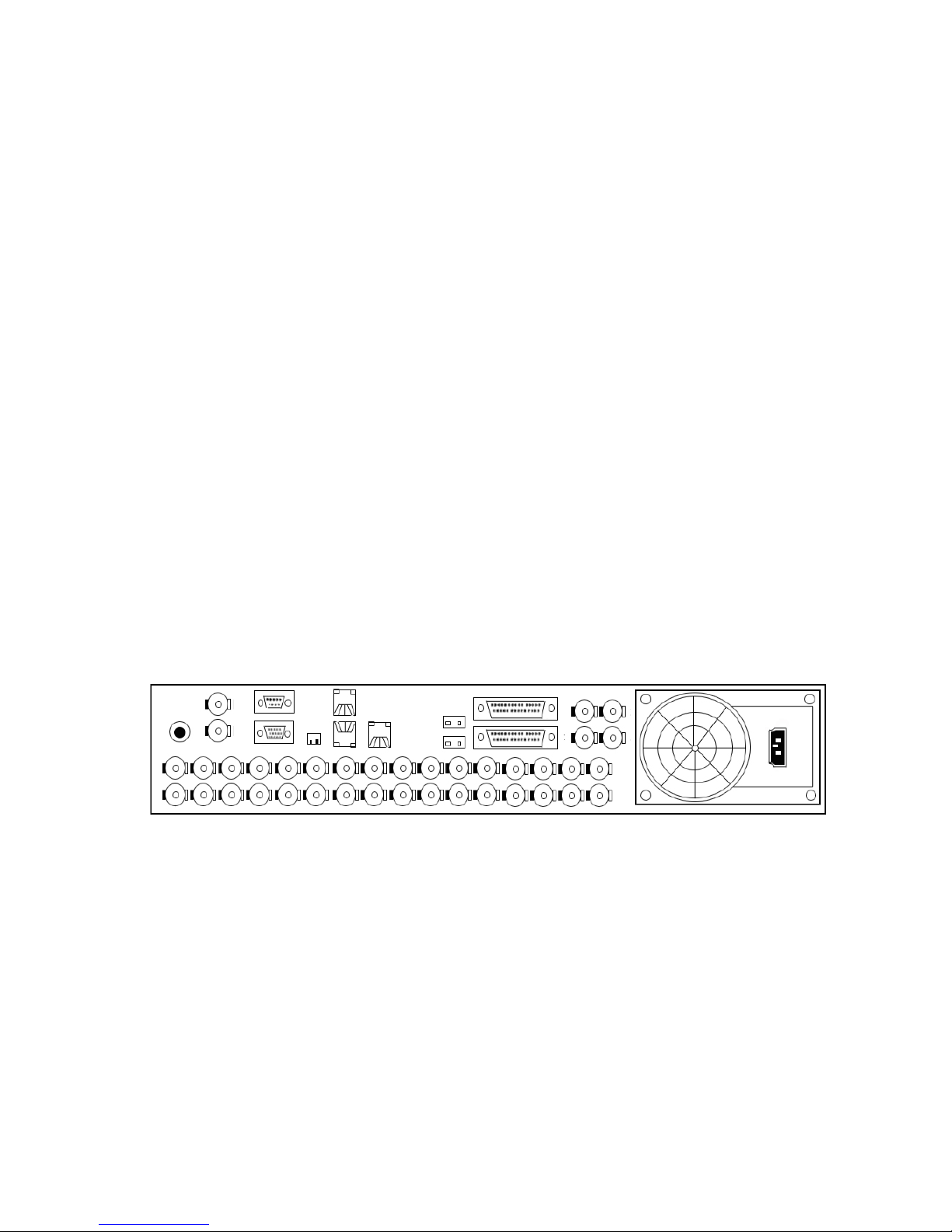
Section 4 Back panel Layout
Back panel layout of the standalone series 24-channel and 32-channel DVR is as follows.
The height of the case is 2U and the dimensions of the unit are 460×440×100mm.
Figure 1. 24-channel and 32-channel DVR back layout
Detailed illustration of the audio, video, PTZ control and alarm input/output of the
24-channel and 32-channel DVR:
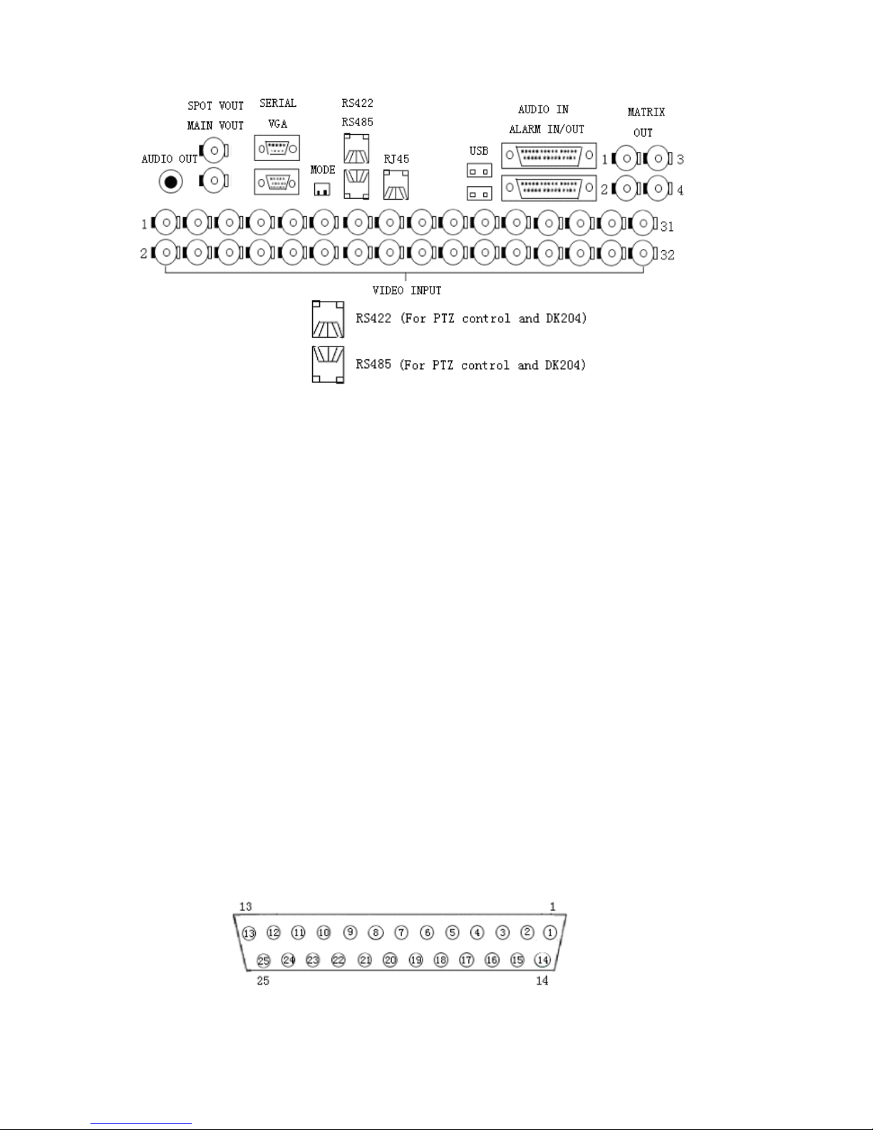
Figure2. 24-channel and 32-channel DVR Input/Output details
Section 5 Video Connections
24-channel DVR has 24 BNC video input ports at the back panel for direct connection with
cameras.
32-channel DVR has 32 BNC video input ports at the back panel for direct connection with
cameras.
Section 6 Monitor and Display Connections
Each of 24-channel and 32-channel DVR has two composite video and a VGA video outputs,
“ SPOT VOUT ” does not include the OSD menu display.
“ MAIN VOUT ” includes the OSD menu display.
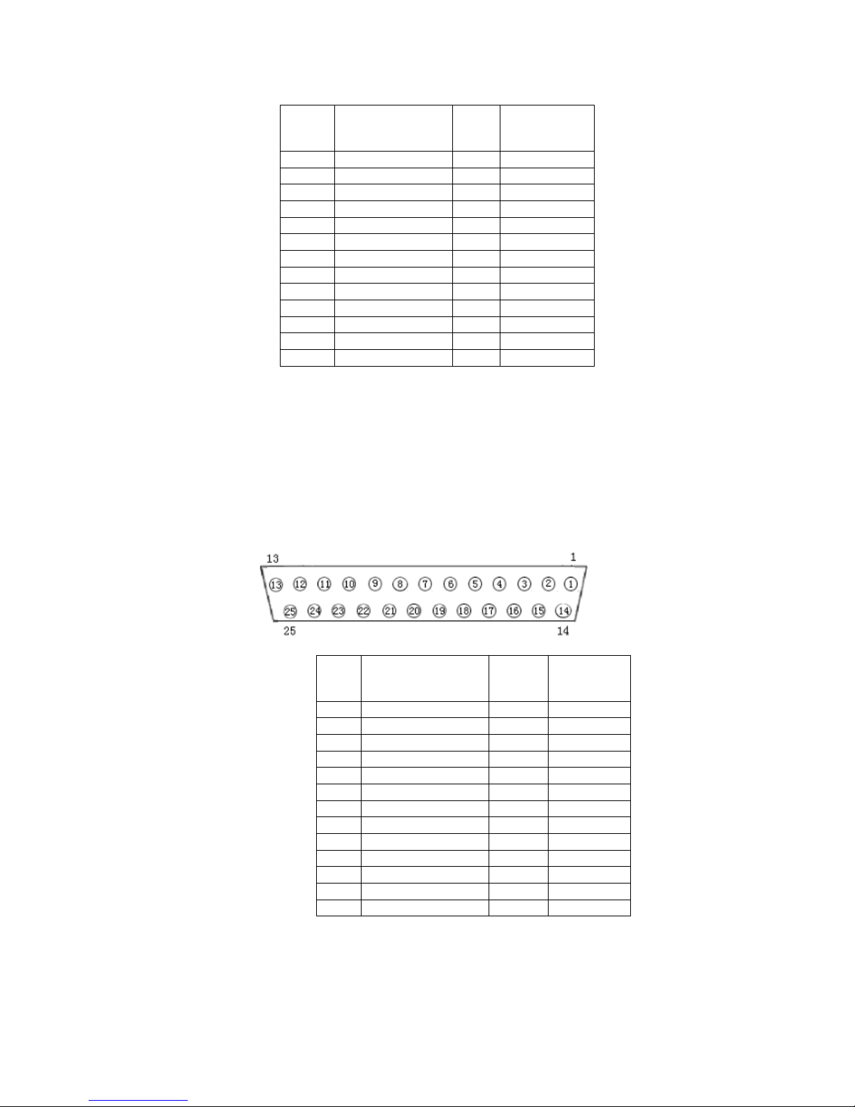
Section 7 Audio Input Connections
Audio/Video recording synchronisation is available for this DVR.
The DVR has its own audio connection cable, which is plugged into the 25-way D type
connector on the back panel of the DVR.
The pin-out definition of the 25 way D-type is as follows:
Section 8 Sensor Input Connections
When the alarm input (MENU->RECORDER->ALARM-REC) is set to “OPEN”, low ( 0 )
level alarms will be detected. When the alarm input (MENU->RECORDER->ALARM-REC)
is set to “CLOSE”, high level ( 1 ) alarms will be detected. Below is the pin out configuration
of the 25 way Alarm D-type and an example of the alarm connections.
PIN
No.
Function
PIN
No.
Function
1 AUDIO IN1 14 GND
2 AUDIO IN3 15 AUDIO IN2
3 GND 16 AUDIO IN4
4 AUDIO IN5 17 GND
5 AUDIO IN7 18 AUDIO IN6
6 GND 19 AUDIO IN8
7 AUDIO IN9 20 GND
8 AUDIO IN11 21 AUDIO IN10
9 GND 22 AUDIO IN12
10 AUDIO IN13 23 GND
11 AUDIO IN15 24 AUDIO IN14
12 GND 25 AUDIO IN16
13
PIN
No.
Function
PIN
No.
Function
1 ALARM IN1 14 GND
2 ALARM IN2 15 NO1
3 ALARM IN3 16 NC1
4 ALARM IN4 17 COM1
5 ALARM IN5 18 NO2
6 ALARM IN6 19 NC2
7 ALARM IN7 20 COM2
8 ALARM IN8 21 NO3
9 ALARM IN9 22 NC3
10 ALARM IN10 23 COM3
11 ALARM IN11 24 GND
12 ALARM IN12 25 GND
13 +12V
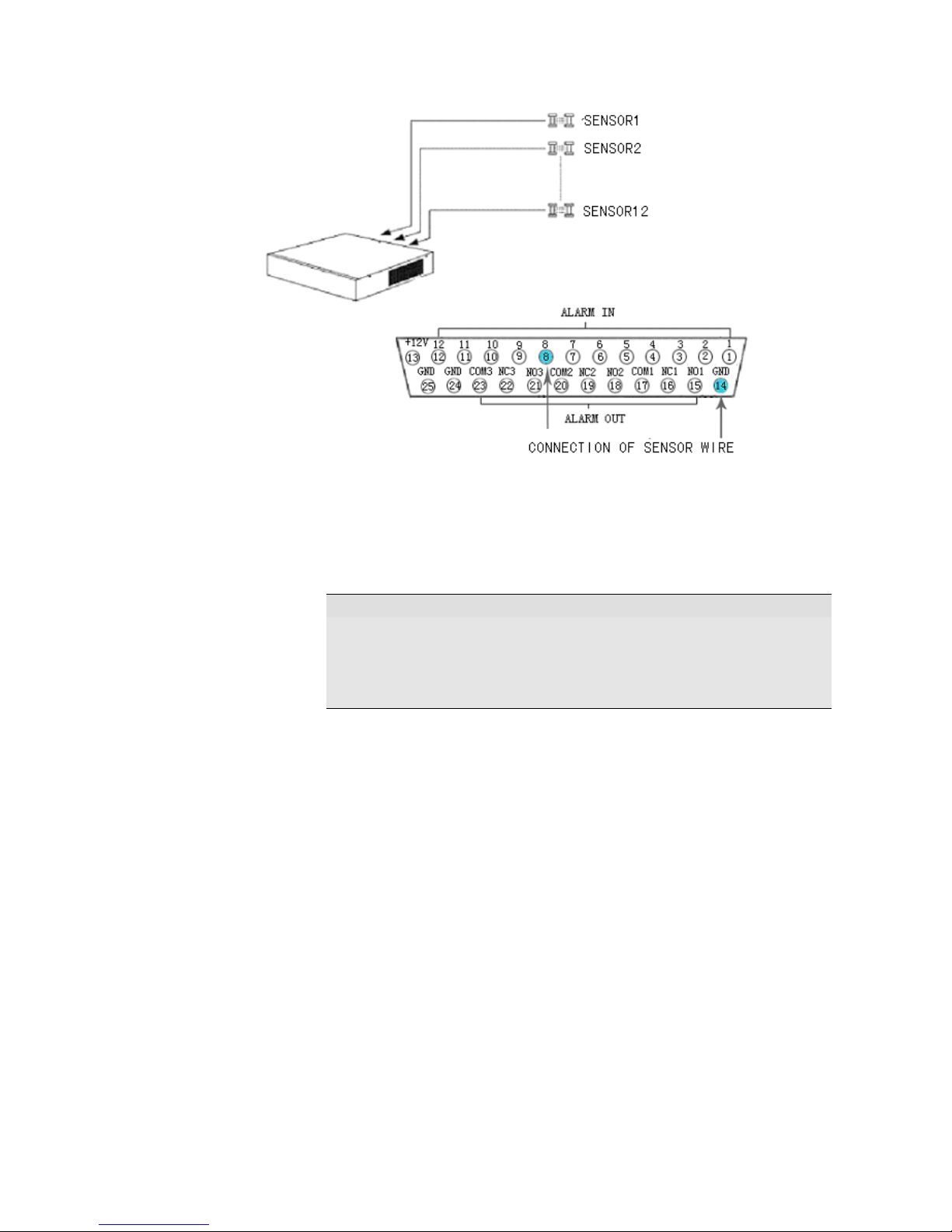
Figure 3. 24-channel and 32-channel DVR Exterior Sensor
Two pins are used in the connection between the sensor and DVR. One connects to the
ALARM IN pin and another connects to the GND pin.
Note
1.12V DC power is provided for most sensors and alarm output
equipment for easier system construction.
2. When the alarm input is set to “CLOSE”, the external voltage
range connected to pin “ALARM IN” is 0-5V.
Section 9 Alarm Output Connections
The DVR provides 3 alarm output ports, with” NO” and “NC” available for each alarm output.
The three alarm signals can be output through a 25 way D- type connector. The connections
are as follows:
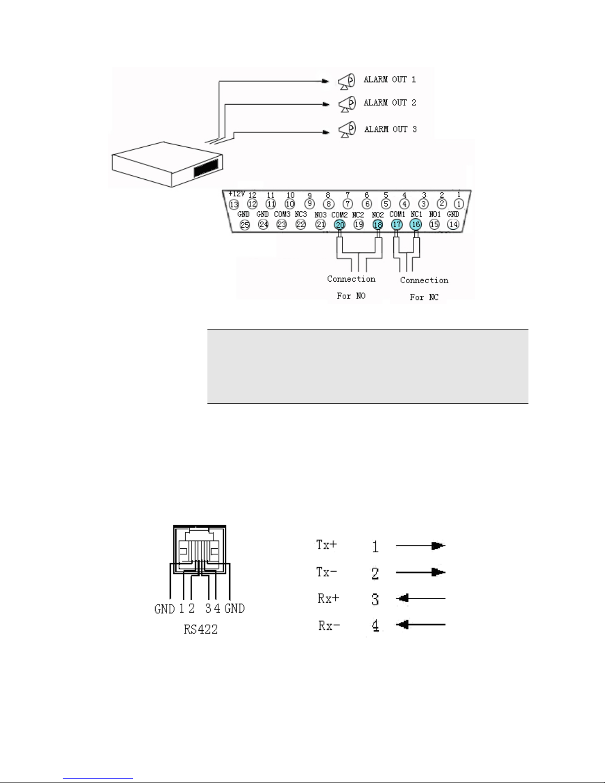
Figure 4. 24-channel and 32-channel DVR Alarm Output Linkage
Note
When alarm output is inactive, “NC” is connected with “COM”,
“NO” is disconnected with “COM”.
When alarm output is active, “NO” is connected with “COM”,
“NC” is disconnected with “COM”
Section 10 PTZ Control Connections
The DVR can control the actions of many PTZs simultaneously through the RS-422 bus, and
identify the PTZ through the address set up by the decoder.
1. RS422
Figure 5. Standard RS-422 detail specification
Cable 1, 2 are positive and negative cable for transmission and can connect to Rx+, Rx- in
PTZ or Speed dome respectively; Cable 3, 4 are positive and negative cable for receive.
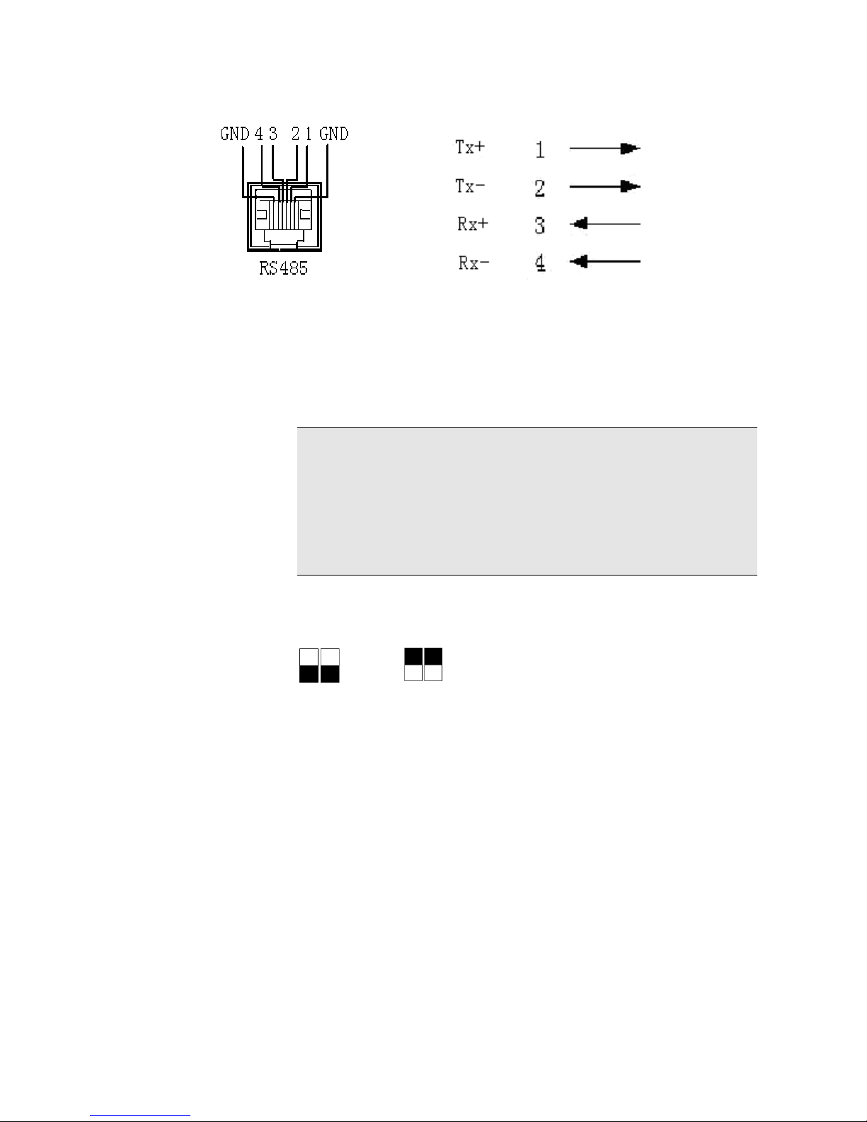
2. RS485
Figure 6. Standard RS-485 detail specification
Cable 1, 2 are positive and negative cable for transmission and can connect to Rx+, Rx- in
PTZ or Speed dome respectively; Cable 3, 4 are positive and negative cable for receive.
PTZ or Speed dome can not be controlled by both RS485 and RS422 at the same time.
Note
PTZ address in system is the same as the camera number, namely::
Camera 1 has PTZ address of 1
Camera 2 has PTZ address of 2
………………
Camera 32 has PTZ address of 32.
PTZ address configurations have to follow the above rule
Section 11 Matching resistance
The switch allows the insertion of a 120 Ohm resistance in the transmission and receive lines.
Switch to the down position means the resistance is NOT in circuit.
Switch to the up position means resistance IS IN parallel connection.
This only applies to the RS422.
Section 12 Network Connections
There is a 100/10M Ethernet network port in the DVR to help connection through a LAN or
direct through a PC.
Network connections for the DVR are as follows:
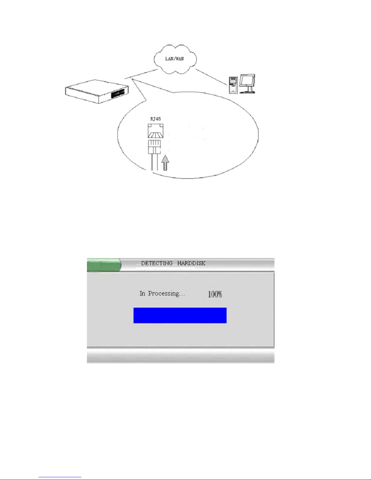
Figure 7. 24-channel and 32-channel DVR Network Connections
Section 13 Getting Started
1. Plug the mains lead into the DVR.
2. The Power indication light then comes on and the following display is shown on the
monitor.
Figure 8. System Startup Graphic
After a short while the start-up graphic disappears. The video from cameras will be displayed
on the monitor and the DVR enters into normal working mode.

Section 14 Network Software Installation
Instructions for installing network browser ‘ Netclient ‘.
The following instructions are for Windows2000/WindowsXP.
The netclient has 3 languages, English, CHS, and CHT.
Network Browser Installation Steps:
Insert the ‘ Netclient ‘ cd into the P.C. optical disc drive and follow the on screen instructions.
It is good practice to remove any previous versions of ‘ Netclient ‘ software.
Chapter III DVR Operation
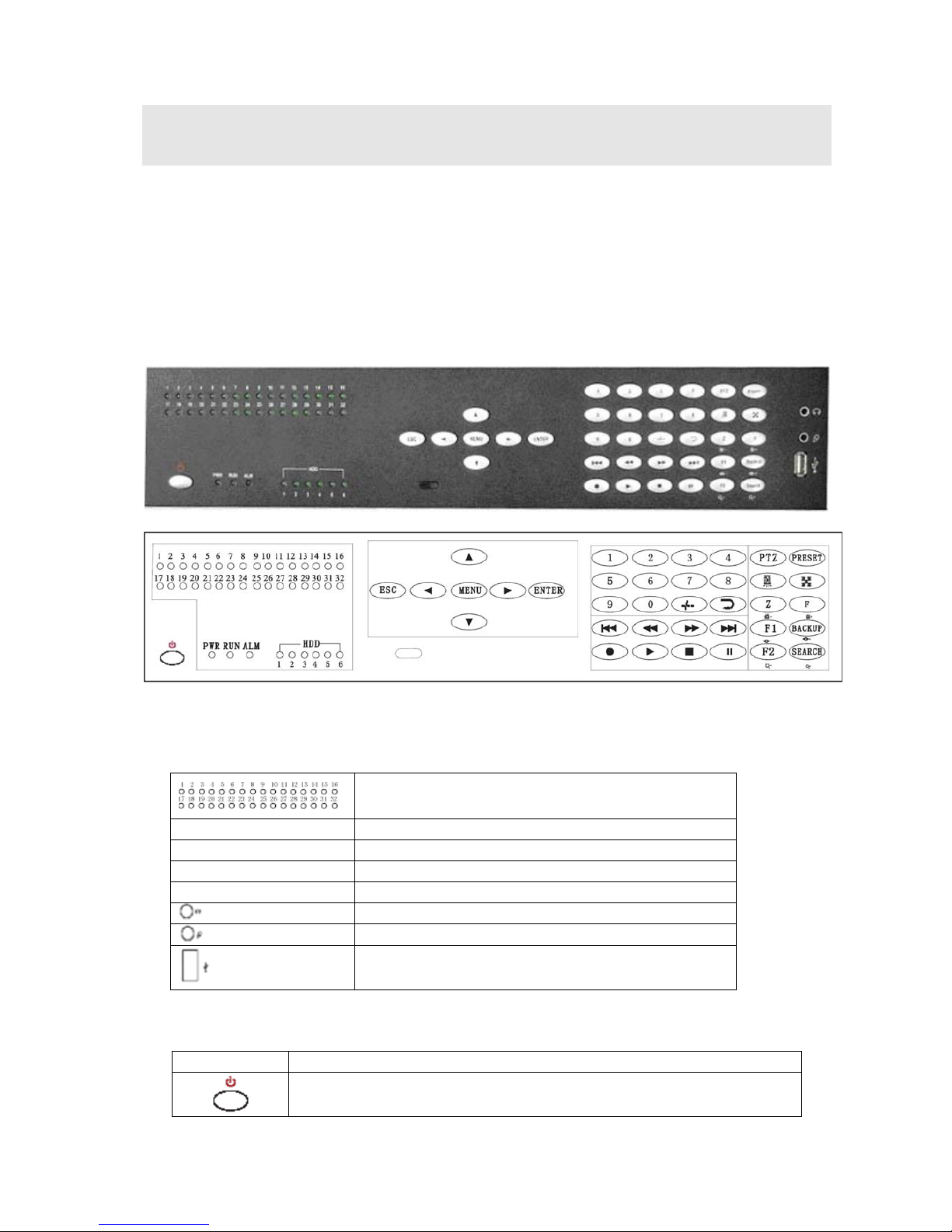
Section 1 DVR Front Panel
The front panel on the DVR includes operational keys and indicator lights. The next section
deals in detail with the function of each key and indicator light on the front panel.
Figure 9. 24-channel and 32-channels DVR Operation Panel
Figure 10.
From left to right the front panel is divided into five function zones: Status indicator zone,
System control zone, Numbers zone, Record/playback zone, and window control zone.
1-32ch record indicator ( it lights when
corresponding channel is recording)
PWR Power indicator
RUN Working indicator
ALM Alarm indicator
HDD 6 SATA HDD indicator
Headphone
Audio output
Microphone
Audio input
USB
USB port (support mouse and removable USB
memory stick)
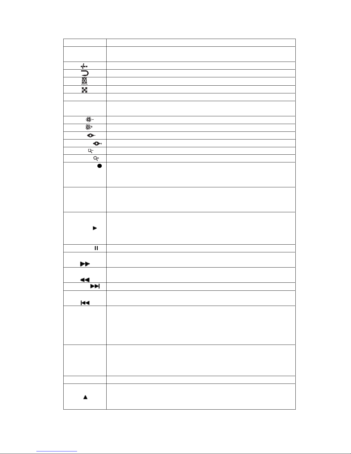
Table 3. Panel Function Definition
Name Function Description
Power switch
0 Number key ‘0’
1~9
1. Number key ‘1’~ ‘9’;
2. Switch from multi-screen mode to channels 1- 9 single-screen
Plus 10
Channel auto-switching (sequencing)
Cancel alarm output
Split screen mode switch, switch between 32\25\16\13\9\6\4 mode
PTZ PTZ enable switch
Preset
Set PTZ preset position for current channel. NB Must be in ‘ PTZ
‘ mode.
Z/
1. Digital zoom; 2.Brightness - in PTZ mode
F/ 1. Freeze picture of current channel; 2.Brightness+ under PTZ mode
F1/ 1. Reserved for future use; 2. Focus- In PTZ mode
Backup/ 1. Entering “Video Backup”; 2.Focus+ In PTZ mode
F2/ 1. Reserved for future use; 2. Zoom – In PTZ mode
Search/ 1. Entering “Video Search”; 2. Zoom + In PTZ mode
RECORD
1. Activate manual recording of current channel
2. Save PTZ initial position of current channel
3. HDD directory check
STOP■
1. Stop recording of current channel
2. Stop playback operation
3. Place PTZ position of current channel back to initial position
PLAY
1. Activate playback of current channel
2. Back to normal playback from fast forward & backwards play
3. Step frame by frame when in PAUSE.
4. Slow play the video at half normal speed
PAUSE Pause current playback
FORWARD Play video forward at a speed of 2, 4, and 8 times
BACKWARD
Play video backward at a speed of 2, 4 and 8 times
NEXT
Jump to next recorded file.
PREVIOUS
Jump to previous recorded file.
ENTER
1.Confirm key when in menu operation or window prompt mode
2.Single image\four image play back mode switch
3.Set up Video Mask
4.Confirm the digital zoom area
4.P/T/Z, lens, aperture and vacancy switch
ESC
1.Cancel key when in menu operation or window prompt mode
2. Back to menu/window state from motion detection area setup state
3. Exit Video Mask setup.
4. Set up mute mode and cancel mute mode
Menu Entering system menu mode
1. Direction key ‘UP’
2. PTZ up direction control
3. Control and zoom the lens closer
4. Set up and move the Video Mask upward
1. Direction key ‘DOWN’
2. PTZ down direction control
3. Control and zoom the lens out.
4. Set up and move the Video Mask downward
1. Direction key ‘LEFT’
2. Control the PTZ to shift left
3. Lens focus near
4. Set up and move the Video Mask left
5. Playback data backward at *2, *4, *8
1. Direction key ‘RIGHT’
2. Control the PTZ to shift right
3. Lens focus far
4. Set up and move the Video Mask right
5. Playback data forward at *2, *4, *8
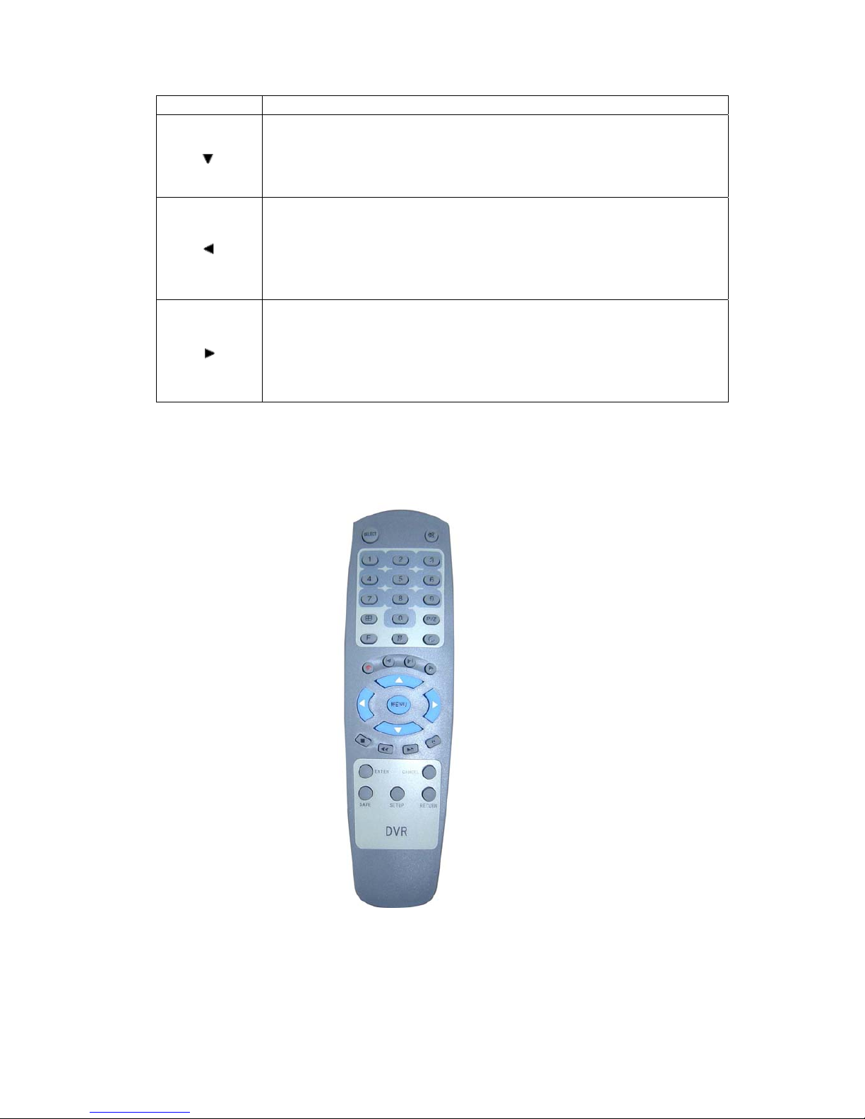
Section 2 DVR Remote Control
The appearance and functions of the keys on the remote control are as follows:
Figure 11. Remote Control
Refer to the section of ‘Panel’ for the detailed description of the keys function on remote
control unit.
Here are the function buttons on the remote control:
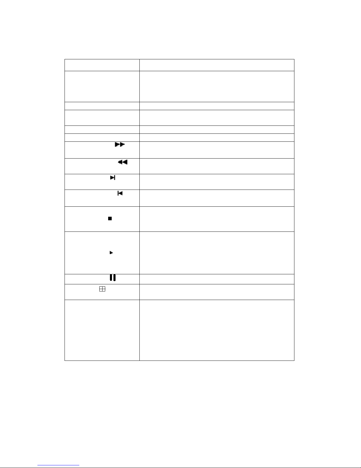
Table 4. Remote controller function Definition
Buttons Functions
Select Input Remote Control Address (000~999), Remote
control address can be the same as the ID of the DVR
system, or remote control address is 000, while the ID
of DVR system is random.
P/Z PTZ enable switch
SETUP 1. Plus 10
2. Set up the origin of current channel PTZ and lens
SAVE Save PTZ preset position of current channel
RETURN Return the PTZ back to origin position
FORWARD
1. Play video forward at a speed of 2, 4, and 8 times
2. “Focus+” In PTZ mode
BACKWARD
1. Play video backwards at a speed of 2, 4 and 8 times
2. “Focus-” In PTZ mode
NEXT
1. Jump to next recorded segment;
2. “Brightness+” In PTZ mode
PREVIOUS
1. Jump to previous recorded segment;
2. “Brightness-“ In PTZ mode
STOP
1. Stop recording of current channel
2. Stop playback operation
3. “Zoom-” In PTZ mode
PLAY
1. Activate playback of current channel
2. Back to normal playback from fast forward &
backward
3. Playback frame by frame under PAUSE mode
4. Slow play the video at half of normal speed
PAUSE
1. Pause current playback; 2. “Zoom+” In PTZ mode
Split screen mode switch. Switch between 32 \ 25 \16 \
13 \ 9 \ 6 \ 4 split screen modes.
CANCEL
1. Cancel key when in menu operation or window
prompt mode
2. Back to menu/window state from motion detection
area setup state
3. Exit Video Mask setup.
4. Cancel intercom
5. Set up mute mode and cancel mute mode
Section 3 Mouse Operation
This DVR supports a USB mouse:
After plugging in the mouse the mouse cursor will appear on the screen.

z In split screen mode, the mouse can adjust the window size of any video channel.
z The mouse can also relocate the window.
Log In.
To Log In right click to bring Menu onto the screen and then left click over the ‘ Main Menu
‘ button.
Next Right Click in the password window and enter the password using the mouse and Left
Click over the correct numbers.
Mouse Operation of the menus.
1. Number Input. Move the mouse cursor to the number box and then right click.
You can then choose the numbers required from the pop – up
box.
2. Edit Parameters. Move the mouse cursor to the option box and then by right or
left clicking the mouse you can cycle through the numbers.
3. Button Operation. When the cursor is over the desired button, left click to confirm.
4. Page up and down. Move the mouse cursor to the up or down arrows on the top left
corner of the window. Select up or down with a left click.
5. Exit or Return. Move the mouse cursor to the ‘ X ‘ or close button. Left click to
exit or return.
Adjusting the Monitor views.
1. Single/Multi-image switch. Click the right key of mouse and select split screen mode either
32/25/16/13/9/6/4/1 in the window by clicking the left key of
mouse.
2. Full screen image. Double click the mouse left key over the required channel
to display full screen image.
3.Split screen Adjustment. Adjust the position and size of any split screen as follows:
Lateral adjustment.
Hold the left key of mouse and drag the right edge of the split screen.
Vertical adjustment.
Hold the left key of mouse and drag the button fringe of split
screen.
Size adjustment.
Hold the left key of mouse and drag the right Edge.

Section 4 Menu Navigation
Table 5. Menu navigation table
Main Menu Branch Menu Functions
System setup Record mode. Auto record when start up. Manual
record quality. VGA resolution setup, etc.
HDD
management
HDD information. HDD format.
System reset Reset system.
Image adjust Adjust the image contrast, brightness, color, etc.
Language setup Select language.
System time Setup time and data.
Version inquiry Information of system firmware version.
Assistant setup Alarm output. Video Mask. HDD error display
setup.
Device
management
Video matrix Matrix output setup.
Search play
back
Search play by time, channel, and event
Time record Setup Record quality, Record frame rate, Record
duration, etc.
Alarm record Setup Alarm input/output ports, alarm time, PTZ
movement etc.
Motion detect
record
Setup Sensitivity, Record duration, record quality
etc.
Record Segment
length setup
Record Segment length setup
Record with
audio
Setup Record with audio for a required channel
Record
parameter
Record parameter Set record resolution for a required channel
PTZ parameter PTZ address, PTZ protocol, baud rate etc.
Set PTZ preset Set PTZ preset under alarm, record and motion
detect modes.
PTZ parameter
RS485 port setup Baud rate, data bits, stop bit etc.
Video channel
Video Mask. Reservation Days.
Communication
setup
Network
parameter
DVR IP address, Server port, Alarm center, port etc.
Operation log Device information
Alarm log Alarm information
Log inquiry
Earliest Record Time of the Earliest Record
Operational
authority
Set the required channel monitor or playback rights
for a non-administrator
Online user
inquiry
Inquiry and cut off the connection of a remote
viewer
Edit Password Edit Password
User
management
Keyboard lock Keyboard lock

Return to default
setting
Return to default setting
Data
management
Record data
backup
Record data backup
Section 5 Menu and Window Interface
The user interface for this DVR is composed of the menu and window interfaces. It’s through
these that the user controls the system. Basic operation is described below.
1. Menu
The basic format of the menu is per following display. The user may use the direction keys,
Up/Down or Left/Right to shift cursor and select the menu. Press ‘Enter’ to enter the main
menu.
Figure 12. Menu
2. Window
Below is an example of a window interface.

Figure 13. Window Interface
Press ‘ up ‘ and ‘ down ‘ to move the cursor.
Table 6. Operation Methods of different Controls
Objects Operation Methods Remarks
Number Input
123
1. Press number keys to input
numbers
2. Use ‘Left’ and ‘Right’ to shift the
cursor position
Date Input
2002-12-06 16:20:32
1. Use number keys to input desired
numbers
2. Use ‘Left’ and ‘Right’ to shift the
cursor position
Cursor is locked
when illegal date
input.
Time Input
12:00
1. Use number keys to input desired
numbers
2. Use ‘Left’ and ‘Right’ to shift the
cursor position
Cursor is locked
when illegal time
input.
Selection Table
Common
Use ‘Left’ or ‘Right’ to select items
Selection Bar
Press ‘Enter’ to select current items
It is used for list
box.
Buttons
Cancel
Press ‘Cancel’ to cancel current
items
It is located at the
bottom of the
window

Chapter IV Basic Operation
Section 1 Login System
Before operating the DVR, you should login to get relevant operational authority. The recorder
has three password levels: Administrator, Operator and Viewer/Browser; the administrator is
the top level and Viewer the lowest level. The security level will be verified according to the
input password. If passwords of different levels are the same, then highest operation level is
granted. Different password levels lead to different operational restrictions.
Note
1. The password consists of Max. 6 numbers, factory default
configuration is set as:
Administrator ——333333
Operator —— 222222
Browser ——111111
2. If wrong password is inputted 3 times, DVR will turn on Alarm.
3. To ensure system security, modify the system default password in
time.
Steps for system login:
1. Press any keys except Split screen mode key and number key
and the entry window will appear.
2. Input the password.
3. Press ‘OK’ to confirm your Password.
4. After password verification, system will remind you of your
level after successful login.

Log On Screen:
Figure 14. Log On Screen
Log On Successful:
Figure 15. Successful Log On
Log On Fail Screen:
Figure 16. Log On Fail Screen

Section 2 Basic Screen
Definition of Screen Partition
The following Split screen modes are available.
Single screen, 4-screen, 6-screen, 9-screen, 13-screen, 16-screen, 25-screen and 32-screen.
Detailed display modes and demand arrangements are as follows.
Figure 17 Screen Display Modes
Display Information Prompt
The distribution of all the information on the display screen is as follows:

Figure 18. System Screen Information
Single channel is as follows:
Figure 19. Information on single Channel

Section 3 Monitor Control
Screen Switch
Split screen and single screen mode may be switched by pressing “ Screen split ” or the
number buttons.
For sequencing interval please refer to “ System / System / Seq. Dwell”.
Then right click to bring up the number selection pad and then enter the dwell time in
seconds.
Operation of Split Key. and Sequence Key
1. Press and the system enters single screen mode if current mode is 32, 25 or single screen
mode; system enters 16, 13, 9, 6 or 4 screens modes if current mode is 16, 13, 9, 6 or 4
screen mode. A “
” symbol will be displayed beside system time.
2. Press again and the sequence mode will be canceled. The symbol beside the
system time will disappear.
Image freeze
“Image freeze” is used to freeze current video image for detail analysis when in live
monitoring mode. Other functions such as recording are not affected by freezing.
Operation Steps:
1. Freeze current video channel by pressing F, with an icon F shown on the left bottom corner
of the channel.
2. When in freeze mode press F again to return to normal mode, icon F disappears.
Note
When in single Image freeze mode, the recorder will automatically return to
the normal running mode if you have selected the Sequencing function.

Audio Monitor
System provides the option to monitor audio. Only the audio from one channel at a time
can be monitored. User may move the cursor to change the channel being monitored.
¾ Press “CANCEL”(remote) or “ESC”(Panel) to cancel the audio. “ ” will be
displayed beside system time.
¾ Press “CANCEL”(remote) or “ESC”(Panel) again to resume the audio output
and the “ ” will disappear from system time.
Section 4 PTZ Control
¾ Way one:
PTZ Control.
Provides control of PTZ operations such as PTZ preset position settings and PTZ original
position setting.
Set Up for PTZ Control.
Access the PTZ setup menu as follows.
Main Menu / PTZ Set Up / PTZ Set Up
You then select the PTZ channel, PTZ address, Baud Rate and Protocol.
Select Connect and then when the channel is selected you have control of the PTZ ( PTZ
mode must be selected ).
Controlling a P.T.Z.
1. Select a channel with a PTZ.
2. Press ‘ PTZ ’ ( panel ), or ‘ P/Z ’ ( remote control ) to enter PTZ. control mode.
3. Use the ‘ Up ’ and ‘ Down ’ keys to adjust the vertical angle of PTZ.
4. Use the ‘ Left ’ and ‘ Right ’ keys to pan the PTZ. left and right horizontally.

5. To define the current PTZ location as the ‘ original ’ position, press ‘ ’ ( panel ) or
‘ setup ’ ( remote control ).
6. To return to the ‘ original ‘ position from current location rapidly, press Stop ‘■ ’
(panel) or ‘ Return ’ (remote control).
7. Press ‘ PTZ ’ (panel) or ‘ P/Z ’ (remote control) and the system will quit PTZ control
mode and return to the normal surveillance mode.
Camera control.
1. Press ‘ PTZ ’ ( panel ) or ‘ P/Z ’ ( remote control ) to enter PTZ. control mode.
2. Use can adjust Focus near and far by use of / (panel) or / (remote
control).
3. User can adjust lens to zoom in and zoom out by use of / (panel) or ■/
(remote control).
4. User can adjust lens aperture by use of / (panel) or / (remote control).
¾ Way two:
PTZ Control.
The PTZ preset position settings and PTZ original position setting please refer to “way
one”.
1. Select a channel with a PTZ.
2. Press ‘Enter’ (panel or remote control) to enter PTZ. Control mode, and the “ ” sign
will appear at the bottom of screen.
3. Use the ‘ Up ’ and ‘ Down ’ keys to adjust the vertical angle of PTZ.
4. Use the ‘ Left ’ and ‘ Right ’ keys to pan the PTZ. left and right horizontally.
5. Press “Enter” (panel or remote control) and the system will enter camera control mode
as shown in following section.

Camera control.
1. User can press “Enter” (panel or remote control) under PTZ. Control mode.
2. The system enters camera control mode with “ ” sign appearing at the bottom of
screen.
3. Use can adjust Focus near and far by use of “Left” and “Right”.
4. User can adjust lens to zoom in and zoom out by use of “Up” and “Down”.
5. Press “Enter” under Lens zoom control mode, the system will enter aperture control
mode with “ ” sign appearing at the bottom of screen.
6. User can adjust lens aperture by use of “Left” and “Right”.
7. Press “Enter” (panel or remote control) and the system will quit aperture control mode
and return to the normal surveillance mode.
NOTE
When the system is in PTZ control mode, other buttons will not be
available except the mentioned buttons. Quit PTZ control mode and
they will be normal.
Section 5 Intercom
Figure 20. Front panel
Connect mike and earphone as shown in Figure 20, connect host with Netclient software, and
click intercom mark to start direct audio communication.
Audio from PC and host will be synchronised.
Section 6 Manual Record
The system provides a manual override video recording function on one channel.
Manual recording will run continuously until the user stops the function.

Operational steps:
1. User presses ‘Record ●’ to enter manual record control interface.
2. User selects channel by pressing “UP” or “DOWN” button, then marking this
channel “■” or “ ” by pressing the ”LEFT” or “RIGHT” buttons. Select “■ ” to
start record; select “ ” to end record; user may select all channels by select “ALL”;
select “NONE” to cancel all channels.
3. The user must press “APPLY” to make the modification effective. Selecting
“BACK” deletes all modification.
Note:
Manual recording will be ineffective if the HDD is fully occupied.
Section 7 Stop Record
If the system is in automatic recording mode, the user can stop recording immediately
through this function. The modes of recording, which can be stopped, include manual, timing,
alarm and motion detect.
Operational steps:
When in manual recording mode, the user can press “stop■” for 2 seconds continuously to
stop the channel recording. If the user presses “stop■” continuously for 5 seconds all
channels recording will stop.
As for timing, alarm and motion detect records when these are active ( please refer to the
sections on “Timer Recording,” “Alarm Recording” and “Motion Detect Recording” for the
specific exiting conditions ), user can press “stop■ ” for 2 seconds continuously to stop
recording the current channel. As soon as record is triggered again, the recording for this
channel will be restarted. Press “stop■” for 5 seconds continuously to stop recording of all
channels. When record of all channels is activated again, the recording of all channels will
be restarted. If the PTZ adjusts automatically at the time of recording, the system will

command the PTZ to return to the original position automatically.
Note
If it’s under the event trigger recording, this function can only stop recording.
It will not affect alarm output. Please refer to section” Alarm Release” for
simultaneous alarm stopping.
Section 8 Playback Control
Playback
For designated channel to enter playback status, this DVR provides two types of
playback: Video search playback and Video direct playback.
Video search playback: Refer to the section on ‘Video Search’, maximum 4 channels
playback synchronously.
Video direct playback: User presses ‘Play ’ of one channel, and the system will enter 4
channel playback interface with the first screen playing back the newest data of current
channel, but remaining 3 screens will not play back. Note that other screens may
playback through video search.
Move to a certain screen, then press “ENTER” to make this screen a full screen, then
press “ENTER” again to return to a 4 split screen mode.
4 split screen play interface is as follows:
Figure 21 Playback

Slow play
When playback is running, user can press ‘play ’ again to enter half normal speed
playback.
If user presses ‘play ’ once again, the system will resume to normal play status.
Stop
In the course of playback, user can press ‘Stop■’ to terminate the current play and
transfer to monitoring mode.
Note
1. Record stop is available under following modes; Step
playback/forward/backward/play. Press” Stop” to end current playing.
2. If it’s under recording and playing modes simultaneously, the function of
stop playback takes priority.
Step Playback
Under the status of playback, user can press ‘Pause ’ to enter Step playback status.
Under this status, user can view frame-by-frame playback video data by pressing
‘Play ’ or direction key of ‘Right’. If pressing ‘Pause’ again, it will return to normal
play status.
Fast Forward
Under playback status, when user presses ‘Fast Forward
’ or direction key of
‘Right’, the system will enter fast forward status.
The system provides three speeds to play video. User can switch between three speeds
by use of ‘Fast forward ’. If user presses ‘Play ’, the system will return to
normal play status.

Fast Reverse
Under playback status, when user presses ‘Fast Reverse ’ or direction key of
‘Left’, the system will enter fast reverse status.
The system provides three speeds to play video. User can switch among three speeds
by use of ‘Fast Reverse ’.
If user presses ‘Play ’, the system will return to normal play status.
Previous
At playback status, when user presses ‘Previous
’, the system will skip to previous
section and play automatically.
Next
At playback status, when user presses ‘Next
’, the system will skip to next section
and play automatically.
Section 9 Alarm Release
This function is for user confirmation that an alarm output by the system has been
acknowledged. When the system outputs an alarm, the system will terminate all alarm
output
including inner buzzer if user presses ‘
’.
Note
Alarm release is only used to stop current alarm output. Re-triggered alarm
output and other functions, such as recording, will not be affected.

Section 10 Remote Control Address Selection
This DVR can be controlled by remote control with the same effect as inputting by the
keyboard panel. The remote control can control one or more DVRs simultaneously. The DVR
identifies the object controlled by the remote control according to system identification. If the
address selected by remote control is not local, all the remote control commands will be
automatically neglected. Remote control address selection provides the function for user to
select and operate the designated DVR. When the DVR is powered, the DVR defaults to
accept remote control commands. If the address is ‘000’, it will be labeled as a broadcast
address and remote control will control all equipment.
Operation steps:
1. User presses ‘Select’ button on remote control.
2. All DVRs within the range controlled by the remote control will pop up an address
selection window. If one DVR within the range controlled by remote control is in
non-idle status such as menu operation or PTZ control etc., this address selection
will not be effective for this machine and it can continue to accept other remote
control commands when it is idle.
3. User inputs the required address. If user selects ‘Enter’, the address selection will
become effective. Otherwise, the address modification will be of no effect.
Section 11 Video Data Backup
This function will back up the current HDD data to the storage facilities except host computer
through USB interface.
Operational process:
1. Insert backup device into USB port.
2. User can select ‘Backup’ through the panel or “Data Backup” through menu (refer
to chapter “Video Data Backup”).
3. Input the search terms for backup and select ‘Enter’.

Backup device note:
1. Remote disk: remote disk has to be formatted as FAT32 format. (A remote disk
more than 32G needs to create sub-regions smaller than 32G, and record files will
be backed up to those sub-regions with FAT32 format).
2. Flash disk: flash disk needs to be formatted with FAT32 format before backup.
Note
If there is any other data in USB disk, please save it, otherwise the original
documents will be deleted when video records backup.
Section 12 Auto Lock
Keypad auto-locking works after a long idle period. A re-login is required for further operation.
Keypad auto-locking starts timing when no system operation is in progress and stops when
user operates the system. The system will display the following prompt if the time of keyboard
automation lock is due:
Figure 22 Keyboard Automatic Lock

Section 13 Power off
Push the power button on front panel and system powers off after password has been
confirmed.
Note
After power off, restart after 10 seconds to protect disk.

Chapter V Advanced setup
The following functions can only be operated by the administrator or the users with
“Parameters Setup” rights. After the confirmation of parameter modifications that take effect
without rebooting the system, parameters that need a reboot to take effect will display a special
reminder.
Section 1 System Equipment Management
System Parameter Setup
Providing basic parameter function for users to configure system.
1. Select ‘System’ in the main menu. Refer to the following.
Figure 23 System Management Menu

Figure 24 System Parameters Menu
2. Select ‘System’ as shown in Figure 24.
3.
Amend the parameters according to the needs or basic operation requirements.
The functions of each parameter are as follows.
Table 7 System Parameters Setup
Items Description Remarks
System ID
Define the ID of DVR for control
through remote controller
Default [001],
Range:[001-999]
Seq. dwell (Single
channel
auto-switching
interval)
Define single channel
auto-switching interval
Default [005s]
Range:[001-999] time
interval can not be set to “0”
Auto Record
(Power on
auto-recording
select)
Auto-recording or not when the
system is powered on
Yes or No
Default No
End of Disk
(Record
overwrite)
Auto/manual overwrite mode when
disk is full
Auto: System overwrites
Manual: user to decide
overwrite or not
Default: Auto overwrite
Video format Select the current video format
PAL or NTSC
Default:PAL
Keylock Time
(Keypad
auto-lock
interval)
Length of idle time before keypad
auto locks
Default [600s]
Range:[005-999]
≥ 5 s
999: never lock
Display Whether to display the channel All, cancel, title and status

title and other information and
icon or not
can be selected
Default: ALL
Beep Alarm
(Buzzer when
alarm)
Buzzer on/off when alarm
triggered
Yes or No
Default: No
Pre-recording Startup pre-record or not ON or Off Default: Off
Rec. Quality
(Image quality
when manual
record)
Select manual record image
quality level
SUPER、HIGH、
STANDARD、BASIC、LOW
Default: STANDARD
Frame I Inter
Define record I-frame interval
Suggestion: use default value
00
VGA Reso (VGA
resolution setting)
Setup VGA output resolution
800×600、1024×768
Or 1280×1024
Default:800×600
(Need to reboot when
changing)
Video Switch
(Trigger source
for video
switching)
Only for ATM special machine,
not for this one
Suggestion: Default: 0
Stream Type
Define the stream of manual
record variable or not
CBR or VBR
Default:CBR
Alarm switch
Define single channel display or
not when the channel is alarm
recording.
ON or OFF
Default: OFF
Frame Rate
Manual record frames
(FULL means 25fps)
FULL、1/2F、1/4F、1/8F or
1/16F Default: Full
Dec. Filter
(
Playback filtering
parameters
Playback filtering parameters setup
Range [0~9]
Default 1
4. Select ‘ENTER’ to confirm your setting, and select ‘Esc’ “Cancel” to give up.
DISK (HDD Management)
Providing the function of inquiry and management of the HDD installed in the DVR. User
must format the new HDD before using it to save the data.
Operational steps:
1. Select Disk.

2. “Disk Information” window will popup, information of all connected HDD’s is
displayed
.
3. When formatting is required, move the select bars to the HDD required and press
“ENTER” button. Formatting status will be displayed on the screen.
Warning
Formatting a HDD will delete all the data in it.
4. When repairing the HDD index is required, move the select bar to the HDD and press
“Record” button.
5. Selecting ‘Previous’ and ‘Next’ will turn the display information back and forward.
6. Selecting ‘Return’ will close the HDD management window.
REBOOT (System Reboot)
User may use this function to reboot system.
Operational steps:
1. Click Reboot.
2. A dialogue box wills popup for the operation.
3. Press “ENTER” to reboot system; Press “Cancel” to cancel instruction.
ADJUST (Display Adjustment)
Video parameter of each current channel can be adjusted separately, with values ranging
from 0-99. Adjustable figure is displayed below.

Figure 25 Display Adjustment
Note
The adjustment screen is the current channel of current focus.
Operational steps:
z Move cursor to the desired channel.
z Click Picture adjust.
z Click “Enter” to enter screen adjust window. Select different item
using ”Up” and “Down”; Change numbers using “Left” or “Right”.
z Press “Return” to finish the adjustment.
Note: There should be a video signal on the channel; otherwise the screen will not be
adjusted.
LANGUAGE (Language Setup)
User can select his own language to operate the system.
Operational steps:
1. Select “Language Setup”.
2. Press “ENTER”, use “LEFT” and “RIGHT” keys to select.
3. Press “OK” to confirm the selection or press “Cancel” to end the selection

TIME (System Time)
Set the system time of DVR.
Operational steps:
1. Select “Time”.
2.Press “ENTER” to display current system time, set new time using number
keys.
3. Press “ENTER” to activate new time; Press “Cancel” to give up
modification.
Warning
System time is very important for the whole system. If you need to modify
system time please close all other functions otherwise exceptions may occur.
VERSION (Version Inquiry)
Software version can be queried from system menu.
Operation step:
1. Select Version.
2. Press “OK”, version information will be displayed.
3. Press ”OK”, again to close the window.
OTHER (Auxiliary Setup)
Figure 26 Auxiliary setup menu

Remote V User (Video Users No.): Providing the channel No.of the DVR users.
Define the network users to connect to the DVR (Max. 32, default: 8);
Alarm Out (alarm output): Refer to “Alarm Record”.
Blind Alarm (Video Shelter): The DVR provides the functions that, user can select
whether to start up alarm input when the menu of camera with channel connection is
sheltered or partly sheltered, and also provides motion detect video.
Blind Value (Shelter Sensitivity): range is 00~99, the level of 99 is the highest and
00 is the lowest.
Disk Error (HDD Error): Hidden or displayed.
HDD Sleep: Sleep modes can be MODEA or MODEB with MODEA by default.
shows the time interval from system power on to disk check, range from 00~99.
When the HDD cannot be found during system startup, this interval may be set
longer, normally is 16~20 (depends on different HDD, 16 is suggestion).
Maintain (System maintain): For more stable operation, may start system auto
maintenance, user input a time for each day for system maintenance (24 hrs). System
will be rebooted at the time.
DST Setting (Summer time setup): Offer summer time setup, press “Setup” to enter
time setup window.
Operational Steps
1. Select Auxiliary Setup;
2. Enter Auxiliary Parameters Setup, amend the types by using ‘Up’ and
‘Down’, and parameters by using ‘Left’, ‘Right’ and number keys;
3. Press ‘Enter’ to make current setup effective, and ‘Cancel’ to cancel
it.
MATRIX SETUP
This function is an optional function. The DVR contains 32x4 Matrix, 4 channels
Matrix output, which makes real time switch surveillance more convenient for user.
Operation Steps:

1. Select Devices Management->Matrix
2. Click “OK”, enter into Matrix Setting Menu, user can choose the different
Option by “Up” and ”Down”, and configure each Option by “Left” and
“Right”. Just as Figure 27 shows:
Figure 27 VIDEO MATRIX
3. Channel: 01-04, Default Setting: 01
4. Camera: 01-32, choose the video you want by enter into “Set”, and multiple
choice is available.
5. Seq. Dwell: 005-999Sec. Default Setting: 000.
Attention: Any Matrix output applied for Multi-Channel switch, the time of switch
must last for more than 5 Seconds or otherwise Auto-Switch will be unavailable.
Section 2 PLAYBACK (Video Search)
As for the recorded video data, user can rapidly search and play the needed video according
to different conditions. The DVR provides 3 modes of video search, they are searching
according by time, by channel or by events and the 3 modes can be combined to search
appointed video data.
Operation Steps:
1. Select ‘Search’ according to the menu.
2. The dialog box of video search will appear and permit the user to input search conditions.
3. User can input channel number, the starting and completing time or the type of video.

The DVR support multiple channels playback synchronously, single channel search
operations: input “Input channel number” number and 00 for other channels, press
“Confirm” and select a file in “Video file search result”; other channels playback are
the same. If all channel numbers are set as 0, files of all channels are searched and default
will be displayed in channel one.
4 channel playback operation steps: input 4 different channel numbers, press “Playback”
and latest video of all channels will be displayed.
Figure 28 Window of Video Search Input
Explanation
When event record search is selected, only event recording data is searched.
Otherwise all type of data is searched.
Event video includes three modes:
1. External alarm event
2. Motion detection event
3. Timing event
4. After inputting search terms, user can press ‘Enter’ to carry out search or press ‘Cancel’
to terminate the video search function.
5. System will pop up video searching results and latest records will be displayed in front.
6. User can select different video data by shifting cursor with the help of ‘Up’ /‘down’.
When there are data of more than one page, user can turn pages to look over by selecting
‘Previous’ and ‘Next’. If user selects some data and presses ‘Enter’, the system will
playback the video data from the selected record. The starting and stopping time is in
accordance with the search terms input by user.

7. For control during playing video, please refer to ‘Playback Control’.
Note
Max. 5000 files will be displayed by search; the records over 5000 will not be
displayed. User may change search criteria to get expected record files.
During playback, when current segment is over, system will continue
playback by jumping to the next segment.
Section 3 RECORDER (Record Setup)
Users can select “Recorder Setup” through the menu as shown in the following Figure:
Figure 29 RECORDER SETUP
SCHEDULE (Schedule Record)
To provide the automatic recording function according to the video time set by user.
Timer Record function can set the video quality, video frame rate, video stream and video
time of each channel separately with the following operational steps:
1. User selects ‘SCHEDULE’ through the menu.
2. Press ‘Enter’ and enter into Timer Record parameters setup menu, then user can select

or input parameters to shift the cursor through direction keys ‘Up’ and ‘Down’ or ‘Left’
and ‘Right’. The menu is shown in following Figure:
Figure 30 Timer Record Menu
3. Channel number: channel from 01 to 32.
4. Video quality: LOW, BASIC, STANDARD, HIGH, SUPER. The default is
STANDARD.
5. Video rate: FULL, 1/2F, 1/4F, 1/8F, 1/16F. The default is FULL.
6. Stream type: CBR or VBR. The default is CBR.
7. Video time interval: Sunday, Monday, Tuesday, Wednesday, Thursday, Friday,
Saturday, ALL. Two time intervals can be set in each day. ‘ALL’ means to record
according to the set time interval in each day. The default is Timer Record Off. Set the ‘OFF’
time interval selection to ‘ON’ after each time interval setup is completed.
8. In the course of setting up the Timer Recording parameters, if the parameters needed to
be set the same in all Channels, user can select ‘ALL’ at the bottom of the menu after
finishing the setup of parameters of one channel. The system will prompt the following
dialog box. When pressing ‘OK’, parameters setup for all Channels will be achieved.

Figure 31 ‘ALL’ Prompt Box
9. User can select ‘Enter’, the current parameters setup will come into force. If user selects
‘Cancel’, the current change will be lost.
Note
24 Channel DVR selects channel from 01 to 24
32 Channel DVR selects channel from 01 to 32
ALARM-REC (Alarm Record)
According to alarm input signals generated by external sensors, system can start
auto-recording and output related alarm signals. Users can setup following parameters:
alarm input port, alarm output port, alarm time length, alarm recording time length, P/T/Z
action, recording channel, recording quality, recording interval.
Operational steps:
1. Select Alarm-REC.
2. “Alarm-REC “dialogue box pops up. Press” Up” or “Down” to move the cursor for
setting, press” Left” or “Right” to select terms and input parameters. The menu looks
like following:

Figure 32 Alarm Recording Setup
3. Alarm In (Alarm input port): from 1 to 16. default as: 1.
4. Alarm Out (Alarm output port): from 1 to 4. default as: 0.
5. Alarm Time (Alarm time length): from 000 to 999. Default as: 030s.
6. Record Time (Alarm recording time length): From 000 to 999. Default as: 060s.
7. PTZ Preset (P/T/Z action: 00.) Default as: 00. PTZ preset can be activated for
corresponding input port.
8. Rec. Cam (Recording channel no.): from 1 to 16. Default as: 1.
9. Rec. Quality (Recording quality): LOW, BASIC, STANDARD, HIGH, SUPER. The
default is STANDARD.
Recording frame rate: FULL, 1/2F, 1/4F, 1/8F, 1/16F. The default is FULL.
Stream type: CBR or VBR. Default as: CBR.
10. Time1 / Time2 (Recording interval 1 and 2): two intervals can be set for each day
within the setup interval external alarm inputs. Leave Time option set to off if not used.
11. Alarm Input (Alarm Input) Open or Close. Default as: Open
12. If all Channels have the same alarm recording parameters, after setup of one channel
press “ALL” below the menu and system will pop up “All setting is applied to all
Channel”, press “Enter” for all Channels to set these parameters automatically.
13. When user selects ‘Enter’, the current parameter setup will come into force. If user
selects ‘Cancel’, the current change will be lost.

Note
If the P/T/Z output is set at 0, it means that P/T/Z will not follow up the
preset
MOTION-REC (Motion detection record)
By detecting the motion in the video, recorder can start motion detection recording.
Parameters like sensitivity of motion detection, motion detection zone, P/T/Z movement,
alarm recording duration, record quality, alarm output port, alarm output duration can be
configured individually.
Operational Steps:
1. Select Motion REC.
2. Press “OK” to popup a dialogue box for parameter setting. Press “Up” or
“Down” to move the cursor for setting, press “Left” or “Right” to select terms
and input parameters.
Figure 33 Motion Detect Record Setup
Sensitivity adjustment and motion detection zone setup are described below in
detail; other parameters setup please refer to “ALARM-REC”.
3. Channel: Channel selected for motion detection.
4. Sensitivity: motion detection sensitivity is from 00 to 99. Default is 50.

5. Area Setup: Click ”set” on certain channel, motion detection zone setup
interface appears:
Figure 34 Motion Detect Area setup
Motion detection setting is only available in the green area, in which the green area
represents the selected area. White area represents the unselected area.
Move the cursor using up/down/right/left keys. Press “OK” for area setup
/clearance.
Press ” Cancel” to return to the dialogue box. Maximum 192 individual areas can be
set. Press ”OK” to make all settings effective. Press “Cancel” to cancel any
changes.
6. PTZ Preset: (P/T/Z action: 00.) Default as: 00. PTZ preset can be activated for
corresponding input port.
7. Record Time (Recording time in seconds)
8. Rec. Quality (Recording quality): LOW, BASIC, STANDARD, HIGH, SUPER.
The default is STANDARD. Recording frame rate: FULL, 1/2F, 1/4F, 1/8F,
1/16F. The default is FULL. Stream type: CBR or VBR. Default as: CBR.
9. Alarm No. Specify alarm number and alarm time in seconds.
10. Time1 / Time2 (Recording interval 1 and 2): two intervals can be set for each
day within the setup interval external alarm inputs. Leave Time option set to off if
not used.

REC-TIME (Record length setup)
Operation steps:
1. Select REC-TIME
.
2. Press “OK”, to pop up a dialogue box for record segment length setting.
3. Input the new length, effective values are between 5~240 seconds/ segment.
4. Press “OK” to activate new settings; Press “Cancel” to cancel changes.
AUDIO (Audio Record)
Audio recording along with video recording can be selected for each channel.
Note
We suggest not to select audio recording when audio is not used.
Operational Steps:
1. Click “Audio recording”.
2. Move the cursor using “Up” and “Down”; Select item using ”Left” or
“Right”.
Press ”OK” to save the setting; Press ”Cancel” to cancel any changes made.
Section 4 RECORD (Re-record Resolution Config.)
Record resolution config to set record resolution for each channel.
Operational Steps:
1. Click “RECORD”.
2. Press “OK”, enter “Record resolution config” menu. Move the cursor using “Up” and
“Down”; Set resolution using ”Left” or “Right”, the channel group can be set 01 to 08,
each group has 4 channels, and each channel can be set to CIF, HD1, or NULL, the
default is: CIF. If you set any channel resolution to HD1 in any group, only the first
and third channel can be set to HD1, then set other channel to NULL make all settings
effective. Please refer to Figure 35:

Figure 35 Record Resolution Config
3. If all Channels have the same video channel parameters, after setup of one group, press
“All” below the menu and system will display “All setting is applied to all Channel”,
then press “Enter” and all Channels will set these parameters automatically.
Section 5 PTZ SETUP (Parameter Setup)
Enter PTZ Setup menu through main menu and the system display the following:
Figure 36 PTZ Setup Menu

Figure 37 PTZ setup
1. Select PTZ Setup.
2. Press “OK” to enter PTZ setup window.
3. Move the cursor using “Up” and “Down”; Select item using ”Left” or “Right”.
4. Press ”OK” to activate new configurations; Press ”Cancel” to give up modification.
5. Set Channel number.
6. Set connect to On if this is a PTZ.
7. Set PTZ Address in menu.
8. Select Protocol.
9. Set Baud Rate & Parity.
10. Set Speed.
11. Set up/down V-Reverse & left/right H-Reverse. (On switches direction)
12. Set Is continue to On.
Pan/Tilt/Zoom
Preset Management
PTZ preset positions are used in alarm recording and motion detection record, PTZs can be
directly tuned to the preset positions when needed. Preset position management function
includes inquire and deletion of preset positions.
Operational steps:
1. Select PTZ preset.
Press
“
OK
” to enter
preset position management window.

Figure 38 P/T/Z Preset Management
2. Move the cursor using “Up” and “Down”; Select item or input parameters using ”Left”
or “Right”.
3. Channel no.: select the channel to be managed.
4. Preset position: select the preset position to be managed.
5. Call: order the P/T/Z of current channel to needed preset position.
6. Original position: order the P/T/Z of current channel to its original position.
7. Delete: delete current preset position.
8. Status: show whether current preset position was set or not.
9. Return: return to its top layer menu.
RS485 Communication Port Setup
Baud rate setup: 9600 (default);
Data bit: 8;
Stop bit: 1;
Check: none;
Section 6 CAMERA (Camera Setup)
Providing functions such as configuration of each video channel connections, displaying
channel location, shelter zone activation and PTZ protocol setup for user.

Operational steps:
1. User selects ‘Camera’ through main menu.
2. Pressing ‘Enter’ key and entering video channel setup menu. User can shift cursor
through ‘Up’ and ‘Down’ and configure each option through “Left” and “Right”. The
menu is shown in the following figure:
Figure 39 Video Channel Connections Setup
3. Channel no: select the channel to be controlled. Default as: 01.
4. Connect: whether to display current channel or not. Default as: On.
5. Mask Area: setup the area to be sheltered in current channel.
6. Mask Active: whether to activate the sheltered area in current channel or not. Default is:
Off.
7. Rec. Reserve: Recording reserved when overwrite. When the disk is full, records of
current channel are not deleted for period of days set.
8. Channel name: display current channel name.
9. If all of the channels have the same video channel parameters, after setup of one channel,
press “All” below, system will display “All setting is applied to all Channel”, then
press “Enter” and all Channels will set these parameters automatically.
10. Press ”OK” to activate new configurations; Press “Cancel” to cancel changes.
Detailed operation steps shelter area setup is shown as follows:
After user enters video area setup, menu will appear

Shelter Area Setup 1 Shelter Area Setup 2
Shelter Area Setup 3
Now, first press ‘Enter’ to separate the cursor of two colors in the figure. Now user can
move the red cursor through direction keys to adjust the area size. Then, user can press
number key ‘1’ to display the profile of shelter area (interface 2) and press ‘2’ to display
all set shelter area (interface 3).
Use direction key to move whole area or adjust area size. If user controls the start position
then move the area; if user controls the end position then adjust the area size.
Press number key “1” and “2” to show its outline or fill the whole area.
Press “OK” to change start position or end position; Press “Cancel” to quit area setup
mode
Note
When applying “All”, the shelter zone setup doesn’t apply to all channels; it
needs to be set individually for each channel.

Section 7 NETWORK
Operational Steps:
1. Enter main menu and select ‘NETWORK Setting’. Press ‘Enter’ to enter and select
‘Network Setup’. The menu is shown as the following figure:
Figure 40 Network Setup Menu
2. User can shift cursor through ‘Up’ and ‘Down’ and configure each option through
‘Left’ and ‘Right’.
3. Select ‘Enter’ to save the modification or select ‘Cancel’ to cancel changes.
4. Set IP Address: Example 192.168.001.100
5. Set Subnet Mask: Example 255.255.255.000
6. Set Gateway: Example 192.168.001.001 (Modem/Router local address)
(If the Subnet Mask is set as above, then the first three levels of the IP address and
the Gateway address must be identical. Use the Gateway address first.)
7. Set Server Port: Example 9998
8. Set Protocol: Usually TCP
9. Alarm Center IP: IP Address for Alarm
10. Alarm Port.
11. Alarm Enable: Set to On if used
12. Link Speed: Auto Mode

Note:
IP address of local and gateway cannot be set as 255.255.255.255.
Server port number cannot be set as 0.
Reboot the recorder to make modification valid if Netclient or IE browser
can’t connect to DVR, and network is OK.
Section 8 REPORT (System Log Operation)
Enter system log inquiry menu, the system will display the following menu:
Figure 41 System Log Menu
System Log
Main system events are recorded in the system log. Records are kept in time sequence.
When the log has 300 system entries, the earliest event will be overwritten.
Operational steps:
1. Select System log
2. Press “Enter” to view current system log information.
3. Click ”PgDn” / “PgUp” to view next/ previous page.
4. Press ”Return” to end the search.

Event Log (Alarm Events)
Alarm events are recorded in the Event Log. Records are kept in time sequence. When
the log has 300 alarm entries, the earliest event will be overwritten.
Operational Steps:
1.
Select
Event Log.
2. Press
“
Enter
”
to view current alarm log information
3. Click ”PgDn” / “PgUp” to view next/ previous page.
4. Press ”
Return
” to end the search.
Oldest Data (Earliest Video)
Entering earliest video, user can inquire time interval of the earliest video on hard disc and
press ‘Enter’ to return.
Section 9 USER INFO User Information Management
Entering user management menu, the system will display the following menu:
Figure 42 User Safety Management
USER RIGHTS
The system can set the access rights of non-administrator to monitor or playback appointed

channel. If the appointed channel set is ‘No Permission’, the operation personnel or
browsing personnel will not be permitted to monitor or playback the images of the channel.
Operation steps:
1. User selects ‘User Rights’ through the menu.
2. Press ‘Enter’ and enter management window of user’s operation rights
3. Set up corresponding operation rights of non-administrators.
4. When selecting ‘All’, it will prompt that ‘All setting has applied for all
Channel’.
5. Selecting ‘Enter’ will save the setup. Selecting ‘Cancel’ will cancel the
modification.
REMOTE USER (Online User)
To provide the connections of remote user in the current system for user’s inquiry. Local
user can terminate the connection of remote user forcedly according to requirement.
Operational steps:
1. Select ‘Online User’ in the menu.
2. Press ‘Enter’ and enter online user information window.
3. User can shift the selection bar by use of ‘Up’ and ‘Down’ direction keys.
4. If user presses ‘Enter’ key on one item in list box, the selected remote user will
be terminated.
5. When user selects ‘Enter’, the system will terminate the remote user. Selecting
‘Cancel’ will cancel any changes.
6. User can select ‘Return’ to end the current inquiry.
PASSWORD (Password Modification)
Provides the function for renewing password. The system will decide the kinds of password
that can be reset by a user according to the user’s rights. Viewer/Browser can only reset the

password of Viewer/Browser, Operator can reset the password of Operator and
Viewer/Browser, and the Manager can reset the password of Manager, Operator and
Viewer/Browser.
Note: If different rights set the same password, the system will prompt the one with biggest
right to enter when inputting password to log on Host.
Administrator: Default password = 333333
Operator: Default password = 222222
Viewer/Browser: Default password = 111111
Operational steps:
1. User selects ‘password’ in the menu.
2. Press ‘Enter’ and enter the window of renew password.
3. User can use the number keys ‘Up’/‘Down’ to reset password. If the user selects
‘Enter’, the reset password will become effective. Selecting ‘Cancel’ will cancel
any changes.
AUTO LOCK
This provides the function to exit the system and lock the keypad for user. After keypad is
locked, it can prevent unlawful user from operating the system to ensure the safety of the
system.
Operational steps:
1. User can select ‘Auto lock’ through the menu.
2. Press ‘Enter’ and enter affirmation dialog box.
3. If user selects ‘Enter’, the system will lock the keypad. If user selects ‘Cancel’,
any changes made are cancelled.
Note:
The key lock function will be performed automatically after long-time
absence. Please refer to chapter ”auto-key lock”.
Manual key lock is also available. If you configure “999” in System Setting,
key lock does not lock anymore.

Section 10 DATA MANAGE (Data Management)
Menu is found on lower section of the Initial Menu page.
The system will display the following menu after entering Data Manage.
Figure 43 Data Management Menu
RESTORE (Restore factory settings)
This function can help user restore the system parameters to factory settings rapidly.
Operational steps:
1. User can select ‘Restore’ through the menu.
2. Press ‘Enter’ and the system parameters will be restored to factory settings. Pressing
‘Cancel’ will cancel any changes made.
BACKUP (Video Data Backup)
Access is through this menu or by pressing Backup button.
This function will achieve the backup of current HDD data to the storage facilities except
host computer through USB interface.
Operation steps:
1. User can select ‘Backup’ in the menu.
2. Press ‘Enter’ and the video backup terms window will popup.

3. Input the search terms of needed backup data and select ‘Enter’.
Backup device Notes:
1. Mobile HDD: The Mobile HDD must format to FAT32.
2. Memory disk: The Memory disk must format to FAT32.

Chapter VI Firmware Upgrade
Section 1 FTP Server Setup
1. Run wftpd32.exe (FTP server software).
2. Select “Security- Users/rights”. The following dialog box will be pop-up.
3. Create new user. Click “new user’. New user dialog pops up. Press ‘OK’ and the password
dialog will popup. (Input user name “user”, password “user”)
4. Press ‘OK’ and the following dialog box will be pop-up.

In the “User/Rights Security” Dialog, select “User Name” as “user”. In “Home Directory” edit
box, input the path where the firmware file (IMAGE) is placed. Then press “Done” to exit.
Wftpd32.exe can be minimized, but it can not be turned off.
Section 2 HyperTerminal
Step 1: Use Serial cable to connect DVR with host PC. Make sure that the DVR and host PC are
in the same sub net. Run the HyperTerminal (setup Baud rate: 9600). Switch on the power
supply of DVR. When the HyperTerminal appears “Press any key to stop auto-boot”,
press any key quickly to enter into “EDVR BIOS”.
Step 2: Input “c” and “ENTER” to edit DVR parameters as follow. After the modification, input
“s” and “ENTER” to save the edited parameters.
[EDVR BIOS]: c
'.' = clear field; '-' = go to previous field; ^D = quit
boot device : idt0
processor number : 0
host name : host
file name : vxWorks

inet on ethernet (e) : 10.0.0.187 //IP address of DVR
inet on backplane (b):
host inet (h) : 10.0.0.216 //IP address of host PC
gateway inet (g) :
user (u) : user //Be consistent with the user name in WFTP
ftp password (pw) (blank = use rsh): user // Be consistent with the password in WFTP
flags (f) : 0x8008 //Modify
target name (tn) :
startup script (s) :
other (o) :
[EDVR BIOS]: s
[EDVR BIOS]:
Note: Don’t modify anything except those noted parameters.
Step 3: Input “u” and “ENTER” to edit DVR parameters as follow:
[EDVR BIOS] : u
Input remote host name : < Ftp Server IP >
Input data file name : < Image File >
Input ftp user name : < user >
Input ftp user password : < user >
After upgrade finished, press any key to reboot DVR.

Chapter VII Product Specifications
Technical Specification
MODEL 24(M) 32(M)
Main Processor Embedded 32 Dual CPU
VIDEO
FORMAT PAL/NTSC
COMPRESSION MPEG4/H.264
INPUT 24 CH BNC (1.0Vp-p, 75Ω) 32 CH BNC (1.0Vp-p, 75Ω)
MAIN OUTPUT 2 CH BNC (1.0Vp-p,75Ω),1CH VGA
MATRIX OUTPUT 4 CH BNC(1.0Vpp,75Ω) ,Group Circular Monitoring
AUDIO
FORMAT G.723/ADPCM
Input DB25,16CH input (100mv-500mv,10KΩ),1CH Mini Jack two way talk
Output
1CH BNC output (100mv-500mv, 600Ω)
1CH Mini Jack for intercom(100mv-500mv,1KΩ)
DISPLAY
Resolution D1:704×576(PAL) 704×480 (NTSC)
Frame Rate PAL (625 lines, 50f/s), NTSC (525lines, 60f/s)
Division 1/4/6/9/13/16/25/36CH, electronic Zoom
RECORDING
Resolution CIF(352*288)PAL,CIF(352*240)NTSC
Frame Rate 25(P)/30(N) FPS Custom Frame supported
Video Quality 5 Levels
Record Mode Manual/Schedule/Events (Motion Detection/Alarm Sensor)
Playback Max.4 CH Playback
HDD
Capability 6 HDD,Max.500G/HDD
Port SATA
ALARM
Input 12 CH (NO/NC Programmable)
Output 3CH (NO/NC Programmable),1A 24VDC/120VAC
OTHER
Work mode Multiplex (Record, Playback, Netview, Netplayback, Monitor)
Network RJ45,10/100M T Ethernet,support PPPoE
Backup Device 3 USB2.0 ports Memory disk,USB HDD,USBCD/DVDRW
Series port 1 RS232 ,1 RS485 ,1 RS422

Mouse USB mouse supported
Power Supply AC100-240V 50/60Hz
Power consumption;
(without HDD)
65W 70W
Weight 12.5KG
Dimensions (W×D×H) 440×460×100 mm (2U)
Colour Black
Operating Environment Operating Humidity 10%~95% -10℃~+55 (14F℃ -131F)

Appendix 1 HDD Capability Calculate
1. Required HDD capacity for one channel one hour (unit Mbyte):
HDD capacity=bit rate / 8 × 3600 / 1024
The unit of bit rate is Kbit/s.
2.Required one channel HDD capacity (unit Mbyte):
HDD capacity=required HDD capacity of one channel for one hour× daily recording time
× number of recording days
3. Required HDD capacity for all channels timing record (unit Mbyte):
HDD capacity=required one channel HDD capacity × the number of channels
4. Required HDD capacity for all channel alarm records (unit Mbyte):
HDD capacity=required one channel HDD capacity × the number of channels ×Alarm
rate

Appendix 2 Operation Notes
Audio input must use active audio sensor. Keep audio sensor away from audio power
amplifier.
When the DVR is in the menu operation mode, remote user can’t modify the parameters
through the network.
Set motion detection sensitivity at 50-80 to effectively detect moving objects.
Following parameters won’t be active unless system reboots after save: auto-recording when
power on, network parameter setup, VGA resolution.
Never attempt to format the hard disk when DVR is recording.
If the buzzer beeps when DVR is in startup, maybe no hard disk is connected or some video input
channel is not connected. Please check these situations.
If no hard disk is connected successfully, no operation related to data storage on hard disk is
allowed.
If unformatted hard disk is connected, user should enter into main menu to format this disk.
When the hard disk is full, and “recording auto overwrite” function is not active, the message
“Hard disk full, recording with overwrite?” will be displayed. Press “OK” to
start overwrite or
press “Cancel” to stop recording.
When the video signal from one channel is lost, the interface for this channel will prompt ‘No
signal’.
When channels from 1 to 4 are displayed in a 4 partition screen, channels from 5 to 8 and
onwards can also be switched by successive pressing of the 4 partition key.
Never change the date or time during recording as it will cause file corruption.

Windows Internet Explorer setup
When using Internet Explorer to login DVR for the first time ensure the following operational
steps are taken:
1. To ensure that you have Microsoft Explorer version 6 of Internet Explorer or higher, and
install DirectX v9.0 or higher.
2. Please find in IE “Tools”→“Internet Option”→“Security”→in “The Custom Security
for Internet” menu→ “ActiveX controls and plug-ins”, use “Enable” for “Download
signed ActiveX Controls”“ Download unsigned ActiveX Controls” “Initialize and script
ActiveX controls not marked as safe for scripting”, please refer following Figure:
Other Options please use default.
3. When you login via the DVR, Internet Explorer will automatically download ActiveX. You
can view the 16 channel display. After successful install, the active user can use “Default
Level” button to return the default level.

When using Web function, please modify the server port of the DVR network parameter as
9998, input the IP of the host in the INTERNET EXPLORER address bar, and add afterward
":998".
For example, for an IP address of "10.0.0.188", please input “http://10.0.0.188:998"in the
INTERNET EXPLORER address bar.

Frequency Asked Questions
¾ Why there is nothing displayed on the monitor when turning on the DVR?
First of all, check if the DVR and monitor have been connected correctly and power is on.
DVR has its own power switch so make sure it has been switched on.
¾
What can we do if the real time monitor image is not clear?
Check all connectors have been connected tightly and are not loose. If the problem is caused by
cables, then they should be replaced or re-soldered.
Check if the aperture and focus of the camera have been correctly adjusted.
Also adjust the brightness and contrast from the DVR system menu.
¾
Why is the motion detection alarm not working correctly. Sometimes there is a person moving
in the motion detection zone but this does not trigger recording?
The accuracy of the motion detection alarm is related to the image from the camera. Try
setting the sensitivity in the DVR to provide a more accurate setting. The value should be
between 50-80.
¾
Why the video records cannot be overwrote automatically?
Reason one: “Auto overwrite record” has not been set on.
Reason two: Disk errors, need to format the disk.
¾
How many recording modes are available?
Schedule/motion detection/alarm/manual recording
¾
Why there is no audio for one channel?
Check if ports and cable connections are correctly connected. If not, try another cable.
Check if the sound monitor works normally.
Check if the mute button on the remote controller has been enabled, and if yes, press it again
to disable.
¾
Why the remote controller does not work?
Check battery is working and has not run down.
Check if the remote controller has been properly setup. If there is a symbol “F” in the left

hand corner of the video, click “F” once more to disable the “F”.
See whether the control address of the remote controller is the same as the ID of the DVR.
If not, then change the address to 000 or ID of DVR.
¾
What should I do if I hear the buzzer when starting up the DVR?
This product is set to trigger the alarm when there is a wrong operation or parameter setting,
so this buzzer is mainly because of no video input. Login as the Manager and
cancel the buzzer.
Check if there is a read/write mistake on the HDD and if so, stop recording and format the
HDD.
¾
Why PTZ movements can not be controlled?
Check if the PTZ control parameters in DVR system menu such as protocol, baud rate and the
address have been set the same as the PTZ.
Check whether the RS485 connecting cable (Tx+, Tx-) of the decoder are correct, and
measure if there is a voltage change between the Tx+, Tx- cables (if the connection is
correct and no voltage change between the cables, it might be a problem with the 485
control chip).
¾
How to use USB to backup the data?
Make sure the backup device has been formatted to FAT32.

Information on Disposal for Users of Waste Electronic Equipment (private
households)
This symbol on the products and /or accompanying
documents means that used electrical and electronic products
should not be mixed with general household waste.
For proper treatment, recovery and recycling, please take
these products to designated collection points, where they
will be accepted on a free of charge basis. Alternatively, in
some countries you may be able to return your products to
your local retailer upon the purchase of an equivalent new
product.
Disposing of this product correctly will help to save valuable
resources and prevent any potential negative effects on
human health and the environment which could otherwise arise from inappropriate waste
handling. Please contact your local authority for further details of your nearest designated
collection point.
Penalties may be applicable for incorrect disposal of this waste, in accordance with national
legislation.
For business users in the European Union
If you wish to discard electrical and electronic equipment, please contract your dealer or supplier
for further information.
Information on Disposal in other Countries outside the European Union
This symbol is only valid in the European Union.
If you wish to discard this product, please contact your local authorities or dealer and ask for the
correct method of disposal.
 Loading...