

Page 1

Instructions for Use
Page 2

Instructions for Use
2
This Manual Copyright © 2018 ITL
All rights reserved. No part of this manual may be reproduced, stored in a
retrieval system, or transmitted, by any means or in any form, without the
prior permission of Integrated Technologies Limited (ITL).
The information contained in this manual is subject to change without notice.
ITL assumes no responsibility for any errors that may appear in this or
related documentation.
Document: V501007
Revision: 3-1810
Vitl is the brand name for Integrated Technologies’ own range of laboratory
products. For further information, please visit the Vitl web site:
www.vitlproducts.com
All sales and technical enquiries should be addressed to:
UK
Vitl Customer Services
Integrated Technologies Limited
Viking House, Ellingham Way, Ashford, Kent, TN23 6NF
United Kingdom
+44 (0)1233 638383
sales@vitlproducts.com
USA
ITL Virginia Inc.
305 Ashcake Road, Suite L, Ashland, Virginia 23005
USA
+1 804-381-0905
sales@vitlproducts.com
CHINA
Integrated Electronic Systems (Shanghai) Co Ltd
T3-11 Unit 201, No. 5001 Hua Dong Road, Pudong,
Shanghai 201201, China
+86 (0)21 585 854 63
sales@vitlproducts.com
Page 3
Instructions for Use
3
Contents
1 Symbols Used in this Instruction Manual ..................................................... 6
2 Safety Precautions and Limitations of Use .................................................. 7
3 Regulatory Limitations of Use ................................................................... 11
4 Lu-mini Unit Description ............................................................................ 12
4.1 Acceptable Sample Vessel Types and Fill Volumes ................................. 15
5 Lu-mini Unit Installation ............................................................................. 16
6 Basic Unit Operation .................................................................................. 17
6.1 User Display and Controls ......................................................................... 17
6.2 Powering-up the Lu-mini Unit .................................................................... 20
6.3 Selecting the Active User .......................................................................... 22
6.4 Selecting a Protocol and Performing a Reading ....................................... 24
6.4.1 Selecting a Protocol .................................................................................. 24
6.4.2 Editing the Sample ID ................................................................................ 25
6.4.3 Sample Vessel Insertion and Removal ..................................................... 27
6.4.4 Performing a Reading ............................................................................... 29
6.4.5 Results Status Tagging and Adding a Comment Note .............................. 31
6.5 Viewing the Test Results Database .......................................................... 33
6.5.1 Deleting Test Results from the Lu-mini Database ..................................... 34
6.6 Using the Timer Function .......................................................................... 35
6.6.1 Using an Independent Timer ..................................................................... 36
6.6.2 Using Linked Cascading Timers................................................................ 38
6.6.2.1 Linking Timers into a Single Cascading Group ....................................... 38
6.6.2.2 Linking Timers into Multiple Cascading Groups ...................................... 40
6.6.3 Using the Timers whilst Sample Testing ................................................... 40
6.7 Unit Set-up Options ................................................................................... 41
6.7.1 Setting the Clock and Date/Time Formats ................................................ 43
6.7.2 Beeper and Button Click Volume .............................................................. 43
6.7.3 Remembering the Last Active User ID ...................................................... 44
6.7.4 Define Automatic Sample ID Text Format ................................................. 44
6.7.5 Reader Test Mode ..................................................................................... 45
6.8 Standby Mode and Unit Shutdown Procedure .......................................... 46
7 Lu-mini Windows App and Advanced Unit Configuration .......................... 48
7.1 Installing the Lu-mini Windows App and USB Driver ................................ 48
7.2 Lu-mini App Basic Functionality ................................................................ 50
7.2.1 Page Selection Buttons ............................................................................. 51
7.2.2 Toolbar Options ......................................................................................... 52
7.2.3 Help Menu Options .................................................................................... 52
7.2.4 Data Table Field Editing and Context Menu .............................................. 53
7.3 Data Synchronisation ................................................................................ 56
7.4 Test Results Database Page..................................................................... 57
7.4.1 Uploading Results Data ............................................................................. 58
7.4.2 Exporting Test Results Data ...................................................................... 58
7.4.3 Deleting Results Data ................................................................................ 59
7.5 User IDs Page ........................................................................................... 59
7.6 Global Unit Settings Page ......................................................................... 60
Page 4
Instructions for Use
4
7.6.1 Adding a New Unit .................................................................................... 61
7.7 Sample Measurement Protocols Page ...................................................... 61
7.7.1 Protocol Name and Reagent Assay .......................................................... 63
7.7.2 Sample Method Types .............................................................................. 63
7.7.2.1 Single Tube Measurements .................................................................... 64
7.7.2.2 Multiple Tube Measurements .................................................................. 64
7.7.2.3 Continuing a Multi-Tube Test from the Worklist ...................................... 66
7.7.3 Measurement Types ................................................................................. 67
7.7.4 Test Result Options and Banding ............................................................. 69
7.7.4.1 Single Sample Result Banding .................................................................... 71
7.7.4.2 Multiple Sample Comparison Bands............................................................ 72
7.8 Reagent Assays Page ............................................................................... 73
8 Troubleshooting ........................................................................................ 75
9 Maintenance and Servicing ....................................................................... 77
9.1 Routine Cleaning and Inspection .............................................................. 77
9.2 Decontamination Procedure ...................................................................... 79
9.3 Transportation and Storage ...................................................................... 80
9.4 Product Disposal ....................................................................................... 80
10 Warranty and Returns ............................................................................... 81
11 Technical Specification ............................................................................. 82
12 Glossary of Terms and Abbreviations ....................................................... 84
WARNING
Please ensure that you have read and fully understood the Safety
Precautions and Limitations of Use in Section 2 of this manual before
attempting to install or operate this product.
Failure to do so could result in severe injury or may damage the unit and
invalidate the product warranty.
Page 5

Instructions for Use
5
Tables
Table 1: Advisory Symbol Meanings.......................................................................... 6
Table 2: Unit Features ............................................................................................. 13
Table 3: Unit Accessories ........................................................................................ 14
Table 4: Acceptable Sample Vessel Types ............................................................. 15
Table 5: Main Menu Button Functions ..................................................................... 17
Table 6: Navigation Button Functions ...................................................................... 18
Table 7: Status and Prompt Symbols ...................................................................... 19
Table 8: Result Status Tag Symbols ....................................................................... 31
Table 9: Timer Function Buttons and Status Symbols ............................................. 35
Table 10: User Preferences and Options ................................................................ 42
Table 11: Automatic Sample ID Buttons .................................................................. 44
Table 12: Lu-mini App Page Select Buttons ............................................................ 51
Table 13: Lu-mini App Toolbar Options ................................................................... 52
Table 14: Lu-mini App Help Menu Options .............................................................. 52
Table 15: Data Cell Context Menu Options ............................................................. 55
Table 16: Test Results Database Data Fields ......................................................... 57
Table 17: User IDs Data Fields ................................................................................ 59
Table 18: Unit Settings Data Fields ......................................................................... 60
Table 19: Time and Date Synchronisation Options ................................................. 60
Table 20: Protocols Table Data Fields ..................................................................... 62
Table 21: Sample Method Options .......................................................................... 64
Table 22: Sample Measurement Types ................................................................... 68
Table 23: Reagent Assay Data Fields ..................................................................... 73
Table 24: Troubleshooting Suggestions .................................................................. 75
Table 25: Lu-mini Unit Error Codes ......................................................................... 76
Page 6
Instructions for Use
6
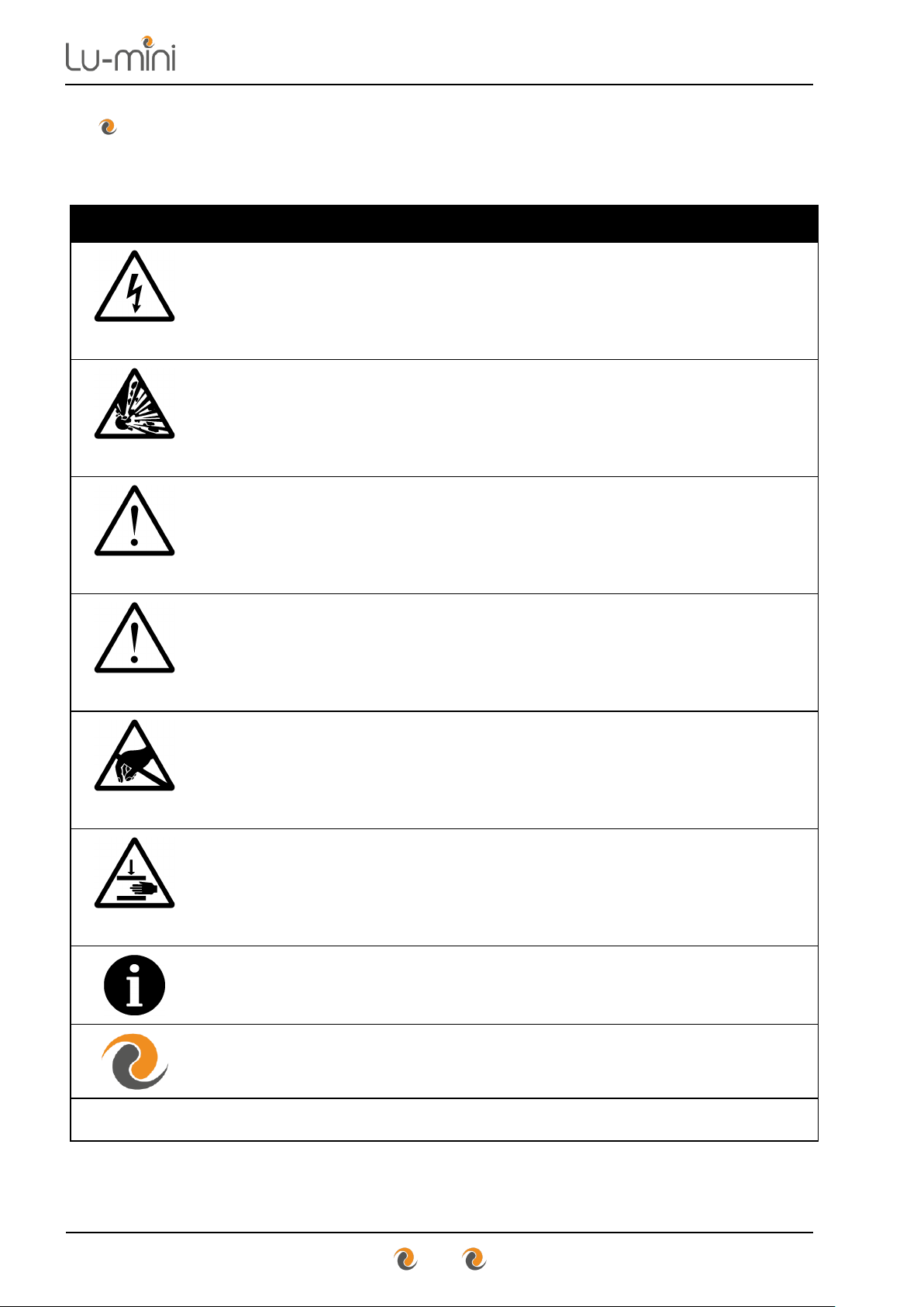
1 Symbols Used in this Instruction Manual
The following advisory symbols are used in this manual.
Table 1: Advisory Symbol Meanings
DANGER
Indicates a Risk of Electric Shock which could, if not avoided,
result in severe injury or death.
DANGER
Indicates a Risk of Explosion which could, if not avoided,
result in severe injury or death.
WARNING
Indicates a hazardous situation which could, if not avoided,
result in severe injury or death; or severely damage the unit.
CAUTION
Indicates a hazardous situation which could, if not avoided,
result in minor or moderate injury; or degrade or impair the
functionality of the unit.
CAUTION
Indicates an Electrostatic-Sensitive Device for which care
should be taken not to touch the exposed electrical contacts
as this could degrade or impair the functionality of the unit.
CAUTION
Indicates a possible crush hazard due to moving parts which
could, if not avoided, result in minor or moderate injury.
Advisory or other useful information.
Refer to Lu-mini App advanced features.
NN
Refer to “Section NN” for more details.
Page 7
Instructions for Use
7
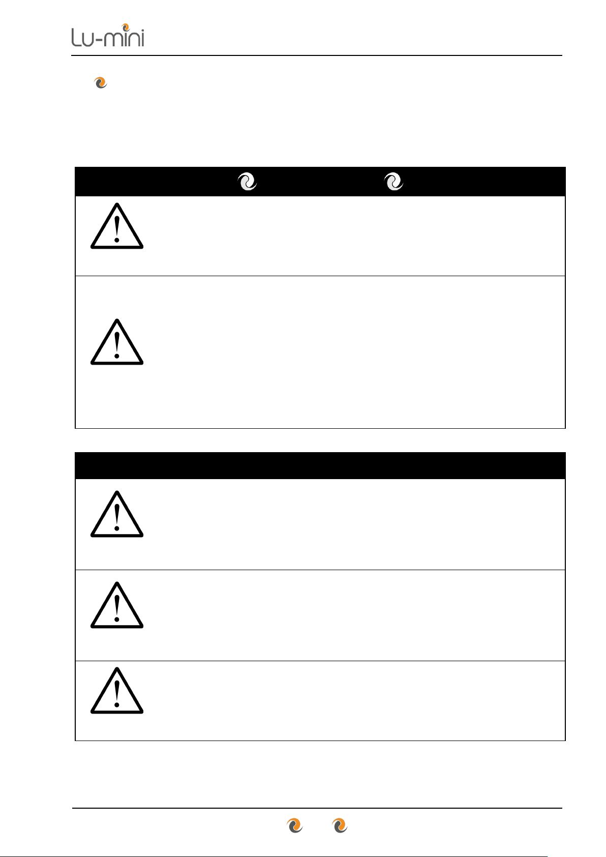
2 Safety Precautions and Limitations of Use
It is essential that all users of this equipment have fully read and understood
the following safety precautions and limitations of use before installing or
operating the Lu-mini unit.
IMPORTANT
WARNING
The protection provided by this equipment may be impaired if
it is not used in a manner described in this manual.
WARNING
It is essential that the user of this equipment is aware of the
potential hazards associated with the unit and its accessories.
All operators should be familiar with the safety precautions
and warnings given in these instructions before attempting to
operate the unit.
Improper use of this unit or its accessories may impair their
functionality and invalidate the manufacturer’s warranty.
Unit Handling Precautions
CAUTION
Care should be taken not to drop the unit or subject it to rough
physical handling, both during normal use and during
installation, transportation and storage.
Do not use the unit if it shows any signs of damage or wear.
WARNING
The unit should be held and supported in both hands when
lifting or moving. Do not lift the unit by the lid.
Care should be taken to avoid trapping fingers under the unit
when placing it down on a solid surface.
CAUTION
Care should be taken not to knock the LCD display.
Do not use excessive force when pressing the touchscreen
buttons or when cleaning it.
Page 8
Instructions for Use
8
Unit Installation and Operating Environment
DANGER
WARNING
The Lu-mini unit is designed for indoor laboratory use only.
The acceptable operating temperature range is 18ºC to 38ºC,
with a relative humidity of 20% to 85% non-condensing, at a
maximum altitude of 2000m above sea level.
If the unit is stored in conditions outside of these ranges, it
must be left to stand unpowered until it has acclimatised to
within these environmental limits before being powered.
DANGER
Use the USB power adaptor provided with the unit.
Care should be taken when powering the unit from a computer
USB port or alternative USB power source.
WARNING
Always ensure that the USB power cord is securely inserted
into the rear of the unit.
Ensure that any excess power cord does not pose a potential
trip or pull hazard.
DANGER
Do not operate the unit in any area which is, or has been, or is
thought to have been exposed to explosive or flammable
gases, vapours or liquids.
WARNING
The unit must be installed and operated on a solid, stable,
vibration-free and level working surface.
CAUTION
For best results, the unit should be installed and operated in a
stable thermal environment, out of direct sunlight and away
from sources of heat or draught.
Page 9
Instructions for Use
9
General Operating Precautions
DANGER
Ensure that the power is switched off at the mains outlet
before inserting or removing the USB power cord.
If a spillage occurs in or over the unit, switch the power off and
unplug the USB cord at the power adaptor before attempting
to deal with the spill.
DANGER
The unit is intended for use with aqueous solutions only.
Never use the unit with any explosive, volatile or highly
reactive substances or chemicals.
WARNING
To avoid liquid spills and possible cross-contamination of
samples, use sealed or capped tubes of the type specified in
Section 4.1.
Always follow prescribed laboratory procedures and use
appropriate personal protective equipment (PPE - such as
gloves, clothing, goggles, etc.) when handling samples.
CAUTION
The unit lid poses a possible finger crush hazard.
Take care when opening and closing the lid to ensure hands,
fingers and protective gloves do not get trapped.
Do not insert your finger into the reader sample chamber.
CAUTION
The unit lid catch contains a small magnet. Avoid direct
contact with any magnetic-sensitive devices or assays.
CAUTION
Avoid touching the contacts of the USB port on the rear of the
unit as an Electrostatic Discharge (ESD) could degrade or
impair the functionality of the unit.
Page 10
Instructions for Use
10
Unit Maintenance and Serviceability
WARNING
There are no user or operator serviceable parts inside the
unit.
Do not remove the unit casework. Removal of the unit's
casework will void the manufacturer’s warranty.
DANGER
Always disconnect the USB power cord from the unit before
performing any cleaning or decontamination procedure.
If liquid is spilt into or over the unit, switch off and disconnect
the USB from the source before attempting to deal with the
spillage.
CAUTION
The use of harsh chemicals and cleaning agents may damage
the unit and degrade its performance.
Always follow the cleaning and decontamination procedures
specified in Sections 9.1 and 9.2 of this instruction manual.
Page 11
Instructions for Use
11
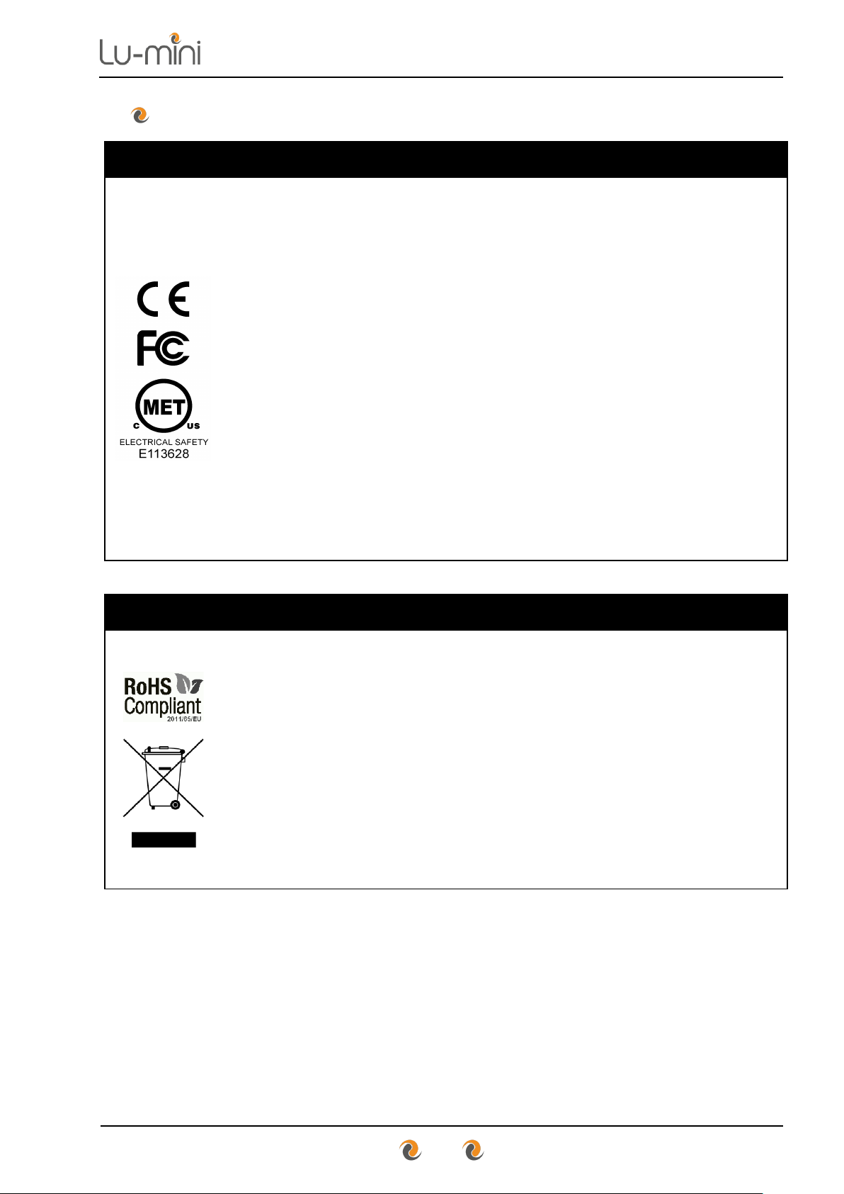
3 Regulatory Limitations of Use
Declaration of Conformity
Integrated Technologies Limited (ITL) affirm that this product
fulfils the essential requirements of the Low Voltage Directive
2014/35/EU and the EMC Directive 2014/30/EU, when
installed and operated in accordance with the instructions in
this manual.
Safety Standards
• EN 61010-1:2010,
• EN 61010-2-010:2003
• UL 61010-1:2001 3nd Edition (CAN C22.2 CSA 61010-1)
• MET Labs NRTL Electrical Safety – Listing No E113628
EMC Standards
• EN 61326:2013, Class A
• FCC CFR 47 Parts 15.107 and 15.109, Class A
RoHS and WEEE Directive Compliance
This product complies with the requirements of the RoHS2
Directive 2011/65/EU for Electrical and Electronic Equipment
and in accordance with BSEN 50581:2012.
Where applicable, the Lu-mini unit should be disposed of in
accordance with the European Union WEEE Directive
2002/96/EC on Waste Electrical and Electronic Equipment.
Do not dispose of this product into unsorted municipal waste
or public landfill. Please refer to Section 9.4 for details of how
to correctly dispose of this product.
The Lu-mini unit is designed and manufactured under ISO 9001 by:
Integrated Technologies Limited
Viking House, Ellingham Way, Ashford, Kent, TN23 6NF
United Kingdom
Page 12
Instructions for Use
12
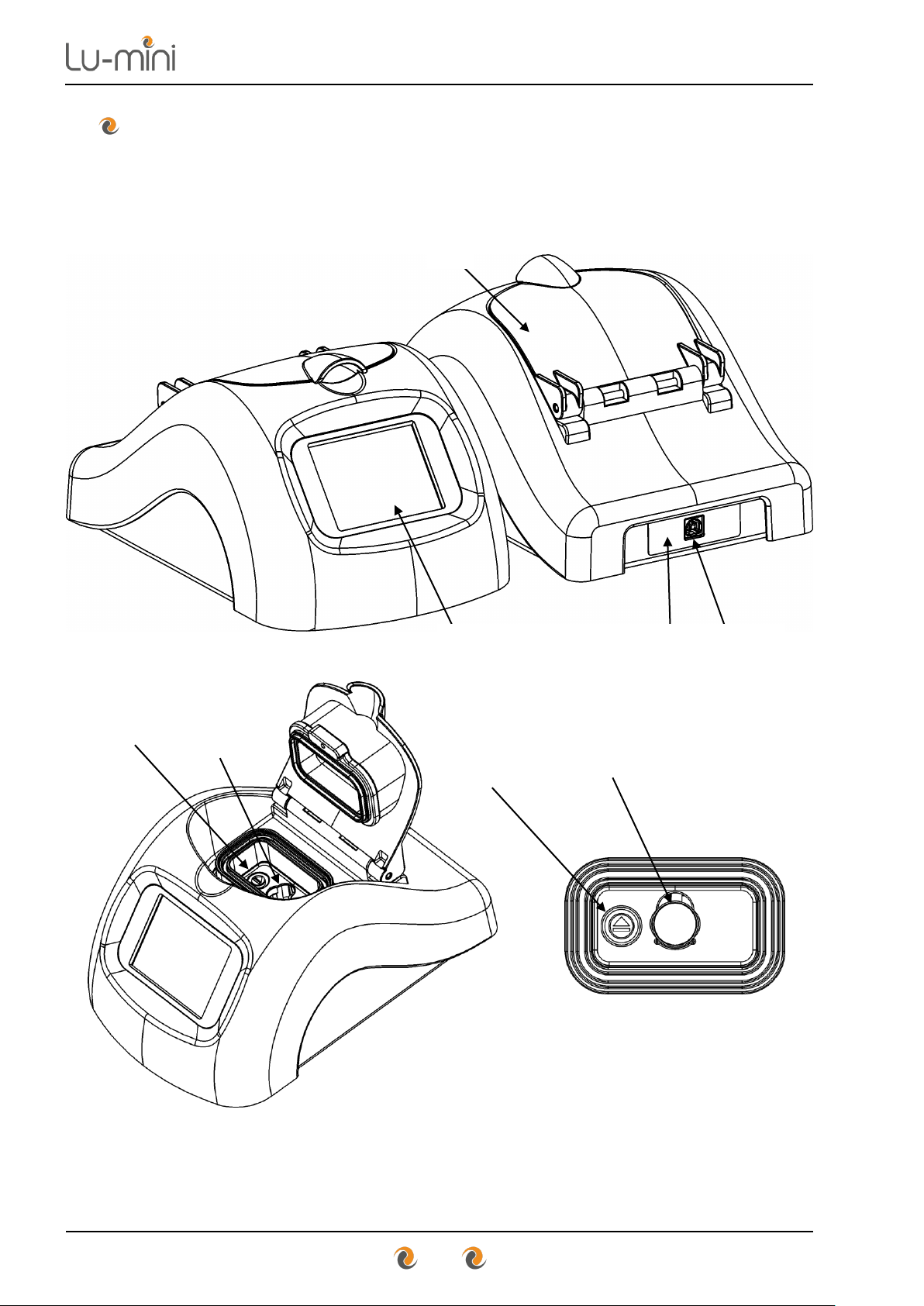
4 Lu-mini Unit Description
The Lu-mini unit is a benchtop Luminometer and has the following external
features:
Page 13
Instructions for Use
13
Table 2: Unit Features
LCD Touchscreen User Interface
6.1
Unit Lid
6.4
Reader Sample Chamber
4.1
Sample Vessel Eject Button
6.4.3
Power Rating
11
USB Power Inlet
0
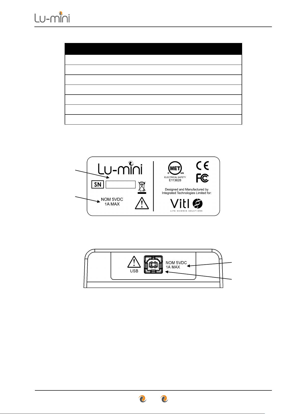
Unit Label and Serial Number
0
The unit label is located on the underside of the unit and provides the unit
serial number, voltage and power ratings:
There is also a label surrounding the USB Power Inlet at the rear of the unit
which provides the voltage and power ratings:
Page 14
Instructions for Use
14
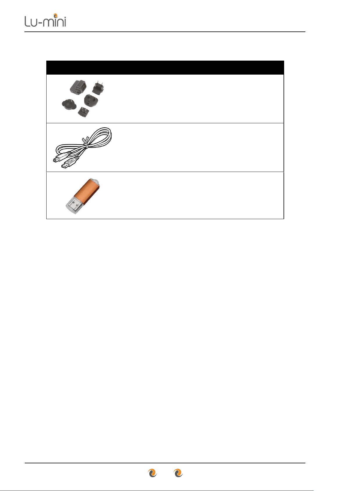
The unit is supplied with the following accessories:
Table 3: Unit Accessories
AC/DC USB Power Adaptor
6.2
USB Power Cable
6.2
11
Lu-mini App Install Flash Drive
7
Page 15

Instructions for Use
15
4.1 Acceptable Sample Vessel Types and Fill Volumes
The Lu-mini unit is designed to accept the following sample vessel types.
Table 4: Acceptable Sample Vessel Types
Vessel Type
Vessels Sizes
Sample Volumes
Tube
Round round-bottomed
10mm to 12mm diameter
47mm# to 75mm* tall
* Including cap
10mm | 12mm
Recommended:
500uL | 800uL
Minimum:
200uL | 300uL
Vial
Round flat-bottomed
15mm diameter
48mm# tall
15mm
Recommended: 1500uL
Minimum: 600uL
Cuvette
Square flat-bottomed
12.5mm square
48mm# tall
10mm path length
12.5mm
Recommended: 1000uL
Minimum: 500uL
The recommended tube type is the 12mm x 75mm (5mL) round-bottomed
polypropylene test tube with a screw cap. Such as:
• Universal Medical Inc - GS-6148R or GS-6148W
• Corning Life Sciences - Falcon 352003 or 352058
CAUTION
To avoid liquid spills and possible cross-contamination of
samples, use sealed or capped tubes whenever possible.
#
Note: Refer to Section 6.4.3 for specific details on how to insert and remove
the sample vessels from the Reader Sample Chamber – particularly for
sample vessels with a height of less than 50mm.
Page 16

Instructions for Use
16
5 Lu-mini Unit Installation
Before installing the Lu-mini unit, please check that the delivery is complete
(see Table 3) and that the unit and all accessory parts are intact and free
from any signs of transportation damage. Also ensure that all external and
internal packaging has been removed from the unit before installation.
Please retain all packaging for future transportation and storage of
the unit and its accessories.
The Lu-mini unit should be installed in a location which meets the following
requirements:
• Safe and suitable operating environment (see Section 2)
• Solid, stable, vibration-free and level working surface
• At least 10cm clearance around the unit to adjacent objects and walls
• Out of direct sunlight and away from sources of heat or draught
WARNING
Please also observe and abide by the Unit Installation and
Operating Environment safety precautions and preconditions
listed in Section 2 of this manual.
When the unit is initially installed, the real-time clock will need to set to your
local time and date. Please read Section 6 first, and then refer to Section
6.7.1 for details.
NOTE
When the unit is initially powered, or if the unit has been in storage
or left unpowered for several months, the internal real-time clock
battery will need recharging.
The unit may report an E85 warning (see Section 8).
Please leave the unit powered for at least 2 hours (preferably 8
hours) to recharge the battery.
Please refer to Section 7.1 for details on installing the associated
Lu-mini Windows App.
Page 17

Instructions for Use
17
6 Basic Unit Operation
WARNING
Please ensure that you have read and fully understood all of
the Safety Precautions and Limitations of Use listed in
Section 2 before attempting to operate the Lu-mini unit.
6.1 User Display and Controls
The unit’s user interface consists of a colour LCD touch screen display. The
menu structure is divided into two main sections as shown below.
Control and Status
Function and Option buttons
The above screen shows the Main Menu buttons, which provide the following
functionality.
Table 5: Main Menu Button Functions
Select active User ID (Any User / Specific User)
6.3
Select Protocol and perform Reading
6.4
View the Test Results Database
6.5
Enter Timer function
6.6
Enter unit Set-up options menu
6.7
Unit Standby and Wakeup modes
6.8
Page 18

Instructions for Use
18
Below is a list of other menu and data list navigation buttons and their
functions.
Table 6: Navigation Button Functions
Accept or Cancel option
6.7
Return to Main Menu
6.1
Return to Previous menu
6.4
Edit Sample ID
6.4
Expand database result
6.5
Test result Status tag
6.4.5
Test result Comment
6.4.5
Jump to Top or Bottom of data list
6.5
Move Up and Down data list
or Increase and Decrease value
6.5
Move to Next value
6.7
Other function-specific button icons are explained in Sections 6.3 to 6.8.
Page 19

Instructions for Use
19
There are also various status and prompt symbols that may appear in the
main screen area, as detailed in Table 7 below.
Table 7: Status and Prompt Symbols
Prompt: Open Lid
6.4.3
Prompt: Insert Sample vessel
6.4.3
Prompt: Use specified Tube Number
6.4.3
Status: Sample Inserted correctly
6.4.3
Prompt: Close Lid
6.4.3
Prompt: Remove Sample vessel
6.4.3
When the lid is open, the unit also periodically beeps to prompt the user to
close the lid as soon as possible.
For optimum reader performance, the lid should always be kept
closed when not inserting or removing a sample vessel.
Please refer to Section 7 for additional buttons and symbols which
relate to specific Lu-mini App features.
Page 20

Instructions for Use
20
6.2 Powering-up the Lu-mini Unit
The Lu-mini unit is powered via a standard USB cable, from the supplied
AC/DC USB Power Adaptor. However, it can also be powered from a USB
port on a desktop or laptop computer, a USB battery pack or a 12V to USB
Car Charger.
AC/DC USB
Adaptor (Supplied)
Computer USB Port
or Powered Hub
USB Battery
Pack
12V to USB
Car Charger
Plug the supplied USB Cable into the Lu-mini Unit and then into the power
source, and (if necessary) switch on the power source.
The Lu-mini unit LCD will light-up and display the power-up progress screen
whilst the internal data memory is checked and the reader initialised.
Power-up Screen
→
Page 21

Instructions for Use
21
Following this the Main Menu screen is displayed.
User ID Screen
Power-Up
Screen
→
Set-up
Standby
The current time and date are displayed on the Main Menu screen as a
visual check that there are correctly set. This is important as the time and
date are required for the Reading and Timer options to function correctly.
Note: If the unit clock is not set, the time and date are displayed in Red and
the Reading and Timer options are disabled until the clock is set.
To set the clock, press the Set-up options button followed by the Date/Time
button. See Section 6.7.1 for more details.
→
→
Date
→ →
Time
→
Page 22

Instructions for Use
22
6.3 Selecting the Active User
The User ID function allows the current active user of the unit to log all the
test results they perform against their own personal User ID. To change the
User ID, press the User ID button from the Main Menu.
User ID Screen
Main
Menu
Screen
→ →
Cancel
Jump to
Top
Move
Up
Move
Down
Accept
By default, the User ID is set to Any User and there are no other User IDs
available to choose from, therefore the Up and Down arrow buttons are
disabled. To return to the main menu press the Accept or Cancel button.
Additional User IDs can only be added and edited via the Lu-mini
Windows Application. See Section 7.5 for details.
When additional User IDs have been downloaded to the unit, the Up and
Down buttons will be enabled to allow the desired User ID to be selected
from the list.
Page 23

Instructions for Use
23
User ID Screen
Main
Menu
Screen
→
→
Cancel
Jump to
Top
Move
Up
Move
Down
Accept
The Padlock symbol ( ) on the right indicates that the User ID is password
protected (see Section 7.5). When selected, the QWERTY keyboard is
displayed to allow the password to be entered.
→
→ → →
→ → →
Main
Menu
Screen
→
→
Enter
password
→ →
The User ID and User Name are displayed on the Main Menu screen, and
the User ID button changes to a solid figure indicating a specific User ID is
active.
By default, the unit remembers the most recently selected User ID and
automatically selects this user when the unit is next powered up. To change
this behaviour, refer to Section 6.7.3.
Page 24

Instructions for Use
24
6.4 Selecting a Protocol and Performing a Reading
Once the User ID has been checked and set, the sample measurement
Protocol can be selected so that a sample test can be performed.
6.4.1 Selecting a Protocol
The Protocol function allows the user to select the appropriate measurement
protocol for the test about to be performed. To select the measurement
Protocol, press the Protocol button from the Main Menu.
Protocol Selection Screen
User ID
Protocol Count
Main
Menu
Screen
→ →
Main
Menu
Worklist
Move
Up
Move
Down
Accept
By default, the Protocol selection list consists of just the Standard RLU
Measurement with no other protocols to choose from, therefore the Up and
Down buttons at the bottom of the screen are greyed-out.
The Worklist button is also greyed-out at this point (see Section 7.7.2.3).
There is a small User ID icon at the top of the protocol screen to indicate the
currently active User ID.
Additional Protocols and Worklists can only be added and edited
via the Lu-mini Windows Application. See Section 7.7 for details.
Page 25

Instructions for Use
25
Once the required Protocol has been selected, press the Accept button to
start the testing procedure.
→ →
Sample
Test
Screen
6.4.2 Editing the Sample ID
The top left corner of the Test screen shows the Sample ID which is a unique
ID assigned to the reading result. The figure in the top right corner of the
screen shows how full the results Database is.
In the middle of the screen the selected protocol is displayed along with the
time and date; and visual prompts to instruct the user on how to perform a
reading.
Sample Test Screen
Sample ID
Database Usage
Protocol
Screen
→ →
Previous
Edit
ID
Select
Location
Tube
Select
Accept
The default Sample ID allocation is a sequential numerical ID - however other
Sample ID options can be selected from the unit Set-up options menu (see
Section 6.7.4 for details).
Page 26

Instructions for Use
26
If desired, the sample ID can be edited at this point by pressing the Edit
button. If this is not required, skip forward to Section 6.4.3.
Edit Sample ID Screen
Test
Screen
→ →
Cancel
Accept
Using the keyboard, the Sample ID can be entered or edited. Once the
desired ID has been entered, press the Accept button to continue or the
Cancel button to undo and return to the Test screen.
Edit
Sample ID
Screen
→
Edit Sample ID
→ →
Sample
Test
Screen
→
No edit required
→ →
If the unit has been set-up to have no automatic Sample ID (see
Section 6.7.4) the QWERTY keyboard will automatically appear as
soon as the test begins.
At the bottom of the sample Test screen, the Location and Tube Select
buttons are greyed-out as these features are only available when using the
Lu-mini Windows Application. See Section 7 for details.
Page 27

Instructions for Use
27
6.4.3 Sample Vessel Insertion and Removal
Once the Sample ID has been set (see Section 6.4.2), insert the test sample
vessel into the reader sample chamber using the following procedure.
→
Open Lid
Insert Sample Vessel
Ensure that the sample vessel is fully pushed down into sample chamber
until the bottom of the vessel is touching the bottom of the chamber.
→
Ensure Vessel Fully Inserted
Close Lid
Once inserted, vessels that are less than 50mm tall are almost completely
enveloped by the sample chamber and cannot be easily retrieved by hand.
→ →
75mm Tube Fully Inserted
48mm Vial Fully Inserted
Page 28

Instructions for Use
28
The Lu-mini features a push button to allow for easy removal of short sample
vessels. The vessel Eject button is located next to the Reader Sample
Chamber inside the unit (see Section 4).
To remove a sample vessel from the reader sample chamber, use the
following procedure:
1) Open the unit lid when instructed.
→
2) If the vessel is easily accessible then it can be simply removed by
hand. If the vessel is difficult to access then the Eject button can be
used.
3) Use a finger to push down on the eject button. As the button is
depressed the vessel will be pushed up out of the sample chamber
slightly.
4) Release the eject button.
5) There should now be enough of the vessel protruding from the
chamber to allow easy removal by hand.
→
→
48mm Vial Fully Inserted
Press Eject to raise Vial
Remove Vial by Hand
Eject Button
Page 29

Instructions for Use
29
6.4.4 Performing a Reading
Once the sample vessel has been inserted into the unit and the lid closed
(see Section 6.4.3 above), press the Accept button start the reading.
→ →
→ →
Open Lid
Insert
Sample
Sample
Inserted
Close Lid
Sample
Ready
Accept
The measurement countdown begins.
At the end of the countdown period the reading result is displayed on the
Test Results screen.
Test Result Screen
Sample ID
Readings Count
Remove
Tube
Status
Tag
Move
Up
Move
Down
Results
Database
Page 30

Instructions for Use
30
At this point the user can choose to either:
1) View the Test Results Database (Section 6.5)
2) Tag the result (Section 6.4.5)
3) Perform another sample test (continue)
4) Return to the Main Menu (continue)
To perform another sample test or return to the Main Menu, open the unit lid
and remove the sample tube just tested. See Section 6.4.3 for sample vessel
removal.
→
Open Lid
Remove Sample
The sample Test screen will then appear. To perform another test, follow the
visual prompts in the middle of the screen as detailed in Sections 6.4.2 thru
6.4.4 above.
Otherwise, to return to the Main Menu press the Previous Menu button and
follow the visual prompts. This will then navigate the user back to the protocol
screen where the Main Menu button can be pressed to return to the main
menu.
→ →
Protocol
Screen
→ →
Main
Menu
Return to
Previous Menu
Close
Lid
Main
Menu
Page 31

Instructions for Use
31
6.4.5 Results Status Tagging and Adding a Comment Note
Each test result can be tagged with a Status icon to signify its overall result
status – as listed in Table 8 below.
Table 8: Result Status Tag Symbols
None: Status unspecified
Good: Good protocol test result
Uncertain: Unclear protocol test result
Bad: Bad protocol test result
Flagged: Result flagged as interesting
Invalid: Invalid/out-of-range test result
The Status tag can be added to the result immediately after the test has
been completed (and before the tube is removed) or when reviewing test
results via the results Database screen (see Section 6.5).
Press the Status tag button to access the status options.
Result Status Screen
Result
Screen
→ →
Cancel
Comment
Accept
Page 32

Instructions for Use
32
For user-defined Protocols (see Section 7.7), the unit’s user can
be prevented from changing the pre-assigned status value, in
which case the status option buttons are greyed-out.
The Comment button can be used to add a short note to the test result. This
is particularly useful when the Flagged status option is selected. This text will
appear in the Notes field of the Lu-mini App Test Results Database table.
→
Enter
comment
→
To change the result status, press the required Status button in the middle of
the screen. The display will jump back to the Result screen with the new
status value shown at the bottom of the screen.
Result Screen
Result
Status
Screen
→ →
Good
Result
The Status tag and Comment can be changed at any time by pressing the
Status button from the Result screen and selecting a different status option.
Page 33

Instructions for Use
33
6.5 Viewing the Test Results Database
The test results Database is where all the test results are stored and can be
accessed either from the Main Menu or test Results screen. To view the
database from the Main Menu, press the Database button.
Results Database Screen
Main
Menu
Screen
→ →
Main
Menu
Jump to
End
Move
Up
Move
Down
Expand
Result
The Database screen displays a list of all the test results that have been
completed. Results are listed in date/time order with the most recent result at
the top of the list.
The Up and Down buttons can be used to scroll up and down the list one
test at a time or alternatively use the jump to Top or Bottom buttons to
quickly jump to the top or bottom of a long list of results.
When a result is highlighted the Expand button can be used to view the fullsize Result screen for that specific result.
Database Screen
→ →
Result Screen
(for highlighted result)
Press the Database button to return to the Database screen.
Results
Screen
→ →
Database
Screen
Page 34

Instructions for Use
34
Likewise, the test results Database can also be accessed directly after a
reading has been taken by pressing the Database button.
Test
Result
Screen
→ →
6.5.1 Deleting Test Results from the Lu-mini Database
Test results cannot be directly deleted from the Lu-mini’s Results Database.
When the database is full, the oldest result is automatically overwritten.
However, they can be tagged as Invalid using the result status tag (see
Section 6.4.5 for details).
Results can only be deleted from the unit via the Lu-mini Windows
Application. See Section 7.4.1 for details.
Page 35

Instructions for Use
35
6.6 Using the Timer Function
The Timer Function provides up to 8 timers that can be individually set from
5 seconds up to 95 minutes. The timers can be operated independently of
each other or grouped together so that when one timer finishes the next one
automatically starts.
Table 9: Timer Function Buttons and Status Symbols
Select Timer (1 of 8)
6.6
Start Timer
6.6.1
Stop Timer
6.6.1
Silence Timer Alarm
6.6.1
Unlinked Independent Timer
6.6.2
Linked Cascading Timer
6.6.2
Status: Timer Inactive (stopped)
6.6.1
Status: Timer Running (started)
6.6.1
Status: Timer Alarming (beeping)
6.6.1
Page 36

Instructions for Use
36
From the Main Menu press the Timer Function button to view the Timer
Summary screen.
Timer Summary Screen
Main
Menu
Screen
→ →
Main
Menu
Start
Timer 1
The Timer Summary screen displays all 8 timers, labelled 1 to 8, with each
being assigned a default time between 0:30 seconds to 60:00 minutes.
6.6.1 Using an Independent Timer
To use a single independent timer, select a Timer from the Timer Summary
screen (e.g. Timer 1 with a default time of 0:30 seconds) to pull up the Timer
Details screen for that timer.
Timer Details Screen
Timer
Summary
Screen
→ →
Previous
Screen
Timer
Unlinked
Increase
Time
Decrease
Time
Start
Timer
Page 37

Instructions for Use
37
The timer duration can be set between 0:05 seconds and 95:00 minutes by
using the Increase and Decrease buttons.
The Timer can then be immediately started by pressing the Start button. The
button will change to a Stop button and the time will start counting down. The
Timer can be cancelled at any time before it reaches 0:00 by pressing the
Stop button.
0:30
→ →
0:30 0:29 0:28
→ →
0:30
If the Timer is left to reach 0:00, the timer Alarm starts sounding and the
Stop button changes to a Silence alarm button. Press the Silence button to
stop the Alarm and reset the Timer.
0:30
→ →
0:30
→
0:00
→ →
0:30
Press the Previous button to return to the Timer Summary screen.
Multiple timers can be started by pressing the Timer select button to go into
the individual Timer Details screen, pressing the Start button to start the
timer and then the Previous button to return to the Timer Summary screen;
and then selecting the next timer to be started; and so on.
→
0:30
→ →
0:30 0:29
→
→
→ →
1:00
→ →
1:00 0:59
→
→
→ →
20:00
→ →
20:00 19:59
→
etc…
The status of all 8 timers can then be monitored, Stopped and Silenced
from the main Timer Summary screen.
Page 38

Instructions for Use
38
6.6.2 Using Linked Cascading Timers
If required, some or all of the timers can be linked together so that when one
timer finishes the next one automatically starts. A timer is always linked to the
next sequential timer i.e. Timer 1 to 2, Timer 2 to 3, and so on.
All the timers can be linked together into a single group or multiple groups.
6.6.2.1 Linking Timers into a Single Cascading Group
Instructions on how to link timers are as follows:
1) Select a Timer from the timer summary screen e.g. Timer 1.
2) Edit the time if required.
3) Press the Unlinked button located at the bottom of the screen.
Timer Details Screen
Timer
Summary
Screen
→ →
Previous
Screen
Timer
Unlinked
Increase
Time
Decrease
Time
Start
Timer
Page 39

Instructions for Use
39
4) On the Link Edit screen press the Link Timer button, and then the
Accept button to save the new setting.
Cancel
Accept
5) The Timer Details screen now shows the Timer Linked button and that
Timer 1 is now linked to Timer 2.
Previous
Menu
Timer
Linked
Increase
Value
Decrease
Value
Start
Timer
6) Return to Previous menu. There is now a small arrow between Timer 1
and Timer 2 to indicate that they are linked together.
7) Select Timer 2 and edit the time as required before returning to the
Previous menu.
8) Press the Start button to start the Timer 1.
Page 40

Instructions for Use
40
9) Timer 1 will start counting down until it finishes, then Timer 2 will start
automatically.
More timers can be added into a linked group by activating the linked function
in each timer sequentially i.e. Timers 3, 4, 5, 6, 7 and 8.
6.6.2.2 Linking Timers into Multiple Cascading Groups
Multiple groups of linked Timers can also be set-up if required i.e. Timer 2
linked to 3 and then Timer 5 linked to 6. To create more than one linked
group the timer at the start of a new group must not already be linked to the
previous timer.
Multiple timer groups are started by pressing the Start button on the
individual Timer Details screen for the first timer in each group.
6.6.3 Using the Timers whilst Sample Testing
It is possible to use the unit as normal whilst the timers are running. Once a
timer has been started press the Main Menu button to return to the Main
Menu, and the unit can continue to be used as normal.
→
Start
Timer
Main
Menu
The active timer/s will not be visible on the unit display; however, when a
timer finishes the alarm will sound and this can be muted by pressing
anywhere on the display no matter what screen is displayed.
Page 41

Instructions for Use
41
6.7 Unit Set-up Options
The unit Set-up menu provides options for customising the unit’s behaviour
and shows the current state of the settings.
Press the Set-up button from the Main Menu screen to view the Set-up
Options menu.
Set-up Options Screen
Main
Menu
Screen
→ →
Main
Menu
Reader
Test
To change a setting, press the associated option button in the middle of the
screen, then select a new value (designated by the green bar) and press the
Accept button to save the new setting.
Cancel
Accept
Page 42

Instructions for Use
42
The available options are summarised in Table 10 and described in the more
detail in the following sub-sections.
Table 10: User Preferences and Options
Set clock and
Date/Time
formats
Year/Month/Day
Day/Month/Year
Month/Day/Year
6.7.1
AM/PM
24 Hour
Beeper volume
Muted
Normal
6.7.2
Touchscreen button
click volume
Silent
Click
6.7.2
Default User setting
Default
Most Recent
6.7.3
Sample ID
auto-text
Edit Prefix
6.7.4
None
Auto Number
Daily Number
Reader
test mode
Test Mode
6.7.5
Page 43

Instructions for Use
43
6.7.1 Setting the Clock and Date/Time Formats
The clock option allows you to change the unit date and time, as well as the
date and time formats (as listed in Table 10).
→
→
DATE
→ →
→
TIME
→
Set
Clock
Date
Format
Adjust
Date
Next
Time
Format
Adjust
Time
Accept
If using the Lu-mini Windows App, the date and time can be
automatically set and synchronised with the computer’s clock. This
will also set the date and time formats. See Section 7.6 for details.
6.7.2 Beeper and Button Click Volume
The unit beeper sounds at the end of each sample measurement and when a
timer has finished. This can be Muted if required.
→
Muted / Normal
Done
Likewise, the LCD touch screen button click can be independently set to
Silent if desired.
→
Silent / Click
Done
Page 44

Instructions for Use
44
6.7.3 Remembering the Last Active User ID
By default, the unit is set to remember the last active User ID each time the
unit is powered up. This option can be changed so that the User ID reverts
back to Any User on unit power-up.
→
Default / Remember
Done
6.7.4 Define Automatic Sample ID Text Format
The Sample ID text format can be edited as required using the sample ID
editor function. From the Set-up menu select the Sample ID Auto-text
button.
Sample ID Auto-text Screen
→
→
Previous
Prefix
Auto ID
By default, the sample ID is set to sequential numeric with no prefix. All the
options for ID editing available are detailed in Table 11.
Table 11: Automatic Sample ID Buttons
Edit Prefix Text (0 to 6 characters)
ABCDEF
No Automatic ID
Sequential Numeric ID (6 digits)
123456
Daily Sequential ID (10 digits)
YYMMDD-123
Page 45

Instructions for Use
45
The Sample ID can be a maximum of 16 characters long i.e. if set to a Daily
Sequential ID with a 6-character prefix. Press the appropriate button/s to set
the sample ID as required.
→
→
→
Set
Auto ID
Prefix
Text
Auto
Text
Done
Note: It is possible to have no automatic ID and no prefix set. In this case,
when a sample Test is performed, the unit automatically prompts to user to
manually enter the Sample ID by displaying the QWERTY keyboard. A
sample ID must be given to the sample before a test can be performed.
6.7.5 Reader Test Mode
The reader test mode allows background reading to be performed either with
or without a sample vessel present in the unit.
Press the Reader Test button on the set-up menu to display the reader test
mode screen.
Reader Test Mode Screen
Set-up
Screen
→ →
Cancel Accept
Page 46

Instructions for Use
46
Press the Accept button to perform a reading using the Standard RLU
Measurement protocol. When the test result is displayed, either press
Accept to perform another reading or press Previous to return to the Set-up
Menu.
Note: As these are only background test readings, they are not stored in the
unit’s results database.
6.8 Standby Mode and Unit Shutdown Procedure
After use, and before switching off the power to the unit, it is recommended
to put it in standby mode.
Firstly remove any sample tube that may be present in the unit, and close the
unit lid.
→
Remove Sample Tube
Close Lid
Then, on the Main Menu screen, press the Standby button to activate the
standby mode.
Standby Mode Screen
Main
Menu
→ →
Wake-up
Page 47

Instructions for Use
47
Once the unit is in standby mode then the power can be safely removed.
When the power to the unit is switched off or disconnected, the
LCD may remain illuminated for several second before going
blank.
To wake-up the unit from standby mode, press the Wake-up button on the
standby screen.
Page 48

Instructions for Use
48
7 Lu-mini Windows App and Advanced Unit Configuration
The Lu-mini Windows App activates the following advanced settings and
features on the Lu-mini Unit:
• Uploading of Test Results to a common results Database
• Export of Test Results to an Excel compatible CSV file
• Creation of User IDs with optional passwords
• Creation of custom Protocols and Assays
• Management of multiple Lu-mini units to ensure common settings
Multiple Lu-mini units can be connected to a single computer using several
USB ports and a powered USB hub.
7.1 Installing the Lu-mini Windows App and USB Driver
DISCLAIMER
THIS SOFTWARE IS PROVIDED "AS IS" WITHOUT WARRANTY OF ANY KIND EITHER EXPRESSED
OR IMPLIED INCLUDING BUT NOT LIMITED TO WARRANTIES OF MERCHANTABILITY OR
FITNESS FOR A PARTICULAR PURPOSE.
INTEGRATED TECHNOLOGIES LTD SHALL NOT BE LIABLE FOR ANY LOSS OF PROFIT, LOSS OF
USE, LOSS OF SOFTWARE, LOSS OF DATA, INTERRUPTION TO BUSINESS, NOR FOR ANY DIRECT,
INDIRECT, INCIDENTAL, SPECIAL, EXEMPLARY OR CONSEQUENTIAL DAMAGES OF ANY KIND
ARISING FROM THE USE OF THIS SOFTWARE OR RELATED THIRD-PARTY SOFTWARE WHETHER
UNDER THIS AGREEMENT OR NOT.
BY INSTALLING OR USING THIS SOFTWARE YOU ARE AGREEING TO BE
BOUND BY THE CONDITIONS OF THIS AGREEMENT.
Page 49

Instructions for Use
49
To install the Lu-mini App, run the Install.msi file from the Installation Drive to
initiate the install procedure. Then follow the on-screen prompts.
The Lu-mini App is designed to run on 32-bit and 64-bit versions of
Windows 7, 8 and 10. To install the software you may require
additional Administrator rights from your IT Administrator.
Next the USB Driver must be installed. This is done by running the
appropriate driver install program from the CP210x_Driver sub-folder on the
Installation Drive and following the onscreen prompts:
• For 64-bit Windows: Run CP210xVCPInstaller_x64.exe
• For 32-bit Windows: Run CP210xVCPInstaller_x86.exe
Alternatively, this can also be done by selecting the Install USB Driver
option from the Help menu in the Lu-mini App (see Section 7.2.3 from
details).
To run the Lu-mini App, click on the Lu-mini App icon on the desktop, or in
the VITL Products section of the programs Start menu.
Desktop
→
Lu-mini App
or
→
Programs
→
VITL Products
Lu-mini App
Page 50

Instructions for Use
50
7.2 Lu-mini App Basic Functionality
The Lu-mini App enables data to be transferred to and from the Lu-mini unit
and a Windows computer, making it easy to add User IDs and customise the
unit with specific sample measurement Protocols.
The application display format consists of a spreadsheet-style layout, with
Page selection buttons down the left-hand side of the screen and a Toolbar
across the top.
Page 51

Instructions for Use
51
7.2.1 Page Selection Buttons
The Lu-mini App features numerous spreadsheet-style Tables, which are
selected by clicking the associated Page button down the left-hand side of
the application Window.
Table 12: Lu-mini App Page Select Buttons
Test Results Database
7.4
Future Feature: Test Results Database Filters
Future Feature: Scheduled Test Sample Work List
Future Feature: Sample Locations
Future Feature: Test Plans
User IDs
7.5
Sample Measurement Protocols
7.7
Reagent Assays
7.8
Unit Settings
7.6
Please refer to the subsequent Sections for more details.
Page 52

Instructions for Use
52
7.2.2 Toolbar Options
The toolbar provides the basic data functions as follows:
Table 13: Lu-mini App Toolbar Options
Sync
Sync Lu-mini Unit to the Lu-mini App
7.3
Save
Save table data changes to disk
7.2.4
Refresh
Refresh page table data
7.2.4
Export
Export data to Excel compatible CSV file
7.4.2
Add
Create new user, protocol, etc
7.2.4
Edit
Edit existing data within App
7.2.4
Delete
Delete existing data within App
7.2.4
Help
Help menu
7.2.3
Close
Close Lu-mini App
Please refer to the specific Sections for more details.
7.2.3 Help Menu Options
The Help Menu is accessed by clicking on the Help button in the toolbar,
and provides the following options:
Table 14: Lu-mini App Help Menu Options
Instructions for Use
Open Lu-mini User’s Manual
Install USB Driver
Install appropriate USB Driver
Check online for App Updates
Future Feature
Capture Unit Screenshot
Capture Lu-mini screen image
Reset Unit Software and Settings
Future Feature
About Lu-mini App
Lu-mini App software details
The Install USB Driver option can be used the install the Windows USB
Driver for the Lu-mini Unit. Using this method, the application automatically
detects the Windows version (32-bit or 64-bit) and loads the appropriate
driver.
Page 53

Instructions for Use
53
The Capture Unit Screenshot option can be useful for taking snapshots of
the current display on the Lu-mini Unit, so that they can be pasted into your
own standard operating procedure documents.
7.2.4 Data Table Field Editing and Context Menu
Each Page displays a specific spreadsheet Table, consisting of a matrix of
data Cells organised in Lines (running down the sheet in rows) of related
data Fields (arranged across the sheet in columns).
Fields ➔
Lines
➔
Lines or Cells which are greyed-out cannot be changed. All other cells in
the table can be edited in any of the following three ways:
(a) Double-clicking on the Cell text:
Cell
→
Edit cell
value
→
Enter
or
Tab
(b) Right-clicking on the Cell and selecting the Edit option from the
Context Menu:
Cell
→
Edit '…'
→
Edit cell
value
→
Enter
or
Tab
Cell
Page 54

Instructions for Use
54
(c) Selecting a table Line and then clicking the Edit button in the
Toolbar:
Line
→ →
Edit cell
value
→
Enter
or
Tab
After changing the Cell text, press the Enter key to accept the new value; or
press the Escape key to cancel editing; or press the Tab key to accept the
new value and automatically move on to edit the next field cell in the line.
WARNING: There is currently no Undo button; hence any changes
made to the table data cannot be easily reversed. The only way to
restore the table values is to Exit the application or to use the
Refresh button (see below for details).
When a data cell value has been changed, the line text colour changes to
Blue to signify that it has been modified but has not yet been saved to disk.
To save any changes to disk, simply click the Save button in the Toolbar.
The modified lines will then turn black again.
Modified
lines
→ →
Data
saved
If changes have been made to the data, but you have changed you mind,
there is no Undo option. However, the entire data table can be reloaded from
disk to the state it was when last saved by clicking the Refresh button.
Modified
lines
→ →
Data
reloaded
New data Lines can be added to the end of the table in two ways:
(a) Clicking the Add button in the Toolbar:
→
New line
added
→
Edit first
cell value
→
Enter
or
Tab
Page 55

Instructions for Use
55
(b) Right-clicking on a Line and then selecting the Duplicate Line
option from the Context Menu:
Line
→
Duplicate
Line
→
New line
added
One or more data Lines can also be deleted in two ways:
(a) Selecting the Lines to be deleted and then clicking the Delete
button in the Toolbar:
Select
lines
→ →
Yes
→
Lines
deleted
(b) Selecting the Lines to be deleted and then Right-clicking on a
Lines and then selecting the Delete Line option from the Context
Menu:
Select
lines
→ →
Delete
Line
→
Yes
→
Lines
deleted
The full list of right-click Context Menu options are as per Table 15 below.
Table 15: Data Cell Context Menu Options
Edit 'field'
Edit cell value
7.2.4
Copy 'field'
Copy cell value to paste clipboard
7.4.2
Copy Line(s)
Copy selected line(s) to clipboard
7.4.2
Copy Line(s) with Header
Copy Header and Selected line(s)
7.4.2
Select All
Select all lines
Select None
Select no lines
Duplicate Line
Duplicate entire line contents
7.2.4
Delete Line
Delete selected line(s)
7.2.4
Please refer to the associated Sections for more details.
Page 56

Instructions for Use
56
7.3 Data Synchronisation
The toolbar Sync button is used to transfer data between the Lu-mini App
and all attached Lu-mini Units, by performing the following tasks:
• Discover and add New Unit details
7.6.1
• Upload test results from Unit
7.4
• Delete test results from Unit’s database
7.4
• Check for Unit Software updates
• Update Unit’s time and date settings [Optional]
7.6
• Update Unit’s User IDs list
7.5
• Update Unit’s Protocols list
7.7
Click the Sync button on toolbar to initiate the data transfer. The Lu-mini Unit
will display the Download screen until the process is complete.
→ &
Sync
Unit Download Screen
App Synchronisation Progress Window
When synchronisation is completed, the Lu-mini Unit will restart. Click the OK
button to close the progress window.
Once restarted, the attached Units will have any new User and Protocol data
loaded on to them from the Lu-mini App, and the App will contain all the test
results data from the Units.
Page 57

Instructions for Use
57
NOTE: Uploading the test results removes them from the Lu-mini
Unit and permanently stores them in the Lu-mini App Test Results
Database table (see Section 7.4).
7.4 Test Results Database Page
The Test Results Database page stores all the test results that have ever
been uploaded from the Lu-mini Units.
The available Test Results Database table data fields are listed in Table 16
below.
Table 16: Test Results Database Data Fields
Results ID
Unit test result unique ID within the database
Unit ID
Unit serial number and name
7.6.1
User ID
User ID
7.5
Date/Time
Date and Time when sample test performed
Location
Sample location name
Patient ID
Optional: Patient ID from Worklist
Sample ID
Test Sample ID
6.4.2
Sample Type
Sample Type (S, C, 1, 2, 3, 4, 5 or 6)
7.7.2
Protocol
Protocol name
7.7.1
Measurement Type
Measurement type
7.7.3
Tube Reading
Sample tube reading
7.7.4
Reading Units
Reading Units-of-measurement
7.7.4
Test Result
Test Result
7.7.4
Results Units
Result Units-of-measurement
7.7.4
Status
Overall test result Status tag
6.4.5
Band
Banded result Name
7.7.4
Lower Limit
Banded result lower limit
7.7.4
Upper Limit
Banded result upper limit
7.7.4
Kinetic Data
Kinetic data points
7.7.3
Notes
Optional: Additional notes
7.2.4
None of these data field values can be modified except for the Notes field.
Page 58

Instructions for Use
58
7.4.1 Uploading Results Data
Each time the Lu-mini App synchronises with Lu-mini Unit any new test
results are uploaded and stored in the Test Results Database table.
→ →
Results
uploaded
Once the results have been uploaded and saved in the Lu-mini App they are
automatically deleted from the Lu-mini Unit.
7.4.2 Exporting Test Results Data
Test results data can be exported to an Excel compatible CSV file by clicking
the Export button on the toolbar.
This can either be the all the data in the table, or just the selected lines.
→ →
Save data
to CSV file
→
Open file
in Excel
Alternatively, the data can be Copied and Pasted into an existing Excel
sheet. This is achieved by selecting the Lines to be copied and then rightclicking on a Line and clicking the Copy Line(s) option in the Context Menu.
Select
lines
→ →
Copy
→
Paste data into
Excel sheet
To export Kinetic Data (see Section 7.7.3 for protocol setting), select the
required results data lines then click the Export button and select the Export
Selected Kinetic Data option.
Select
lines
→
Export Selected
Kinetic Data
→
Save data
to CSV file
→
Open file
in Excel
Page 59

Instructions for Use
59
7.4.3 Deleting Results Data
Results are automatically deleted from the unit when they are uploaded to
the application during the synchronisation process. All results data from the
unit is stored on the application until it is deleted by the user.
To delete results data from the application’s Test Results Database, refer the
Section 7.2.4 for details.
7.5 User IDs Page
By default, the Lu-mini unit has only a single generic Any User user profile.
This page of the application allows for custom User IDs to be created for the
unit as required.
New users are created by adding a new line to the User IDs table (see
Section 7.2.4).
→ →
Edit new User
ID fields
The available User IDs table data field options are listed in Table 17 below.
Table 17: User IDs Data Fields
Active
Selects whether the User ID is downloaded to the unit
Below
User ID
Unique User ID
6.3
User Name
Name associated with the User ID
6.3
Password
Optional password
6.3
Notes
Optional: Additional notes
7.2.4
New User IDs will appear on the Lu-mini unit when the Sync button is next
clicked.
→
Save
Sync
New User IDs are created with the Active field set to Yes, meaning the User
ID will be loaded onto the Lu-mini unit when it is next synchronised with the
application.
There is no limit to the number of User IDs that can be created in the Lu-mini
App, however only 50 active Users IDs can be stored in the Lu-mini Unit.
Page 60

Instructions for Use
60
Hence, to limit the size of this list, the Active field must be changed from Yes
to No for some Users IDs.
7.6 Global Unit Settings Page
The Unit Settings table stores a list of all the Lu-mini units which have been
synchronised with the Lu-mini App.
The available Unit Settings table data fields are listed in Table 18 below.
Table 18: Unit Settings Data Fields
Unit Number
Fixed: Unique Lu-mini Unit serial number
Unit Name
Optional: Name that appears at the top of unit’s Main
Menu screen
7.6.1
Last Synced
Fixed: The date and time with unit was last
synchronised
Notes
Optional: Additional notes
7.2.4
Time and Date Synchronisation options are listed in Table 19 below.
Table 19: Time and Date Synchronisation Options
Time Format
AM/PM or 24H: Used on unit display and in the
Test Results Database table
7.4
Date Format
YYYY/MM/DD, DD/MM/YYYY or
MM/DD/YYYY: Used on unit display and Test
Results Database table
7.4
Automatically set
unit time and date
Selects whether unit’s time/date settings are
automatically updated when by Sync update
Page 61

Instructions for Use
61
7.6.1 Adding a New Unit
New Lu-mini units are automatically added to the Unit Settings table
whenever a Sync is performed.
The Unit Name field can then be set with a short description that appears on
the unit’s Main Menu screen next time the unit is synchronised.
7.7 Sample Measurement Protocols Page
By default, the Lu-mini Unit has only the Standard RLU Measurement
protocol. This page allows custom protocols to be created and developed as
required.
To create a new Protocol, click the toolbar Add button and then enter all the
appropriate data field values.
→ →
New Protocol created
(edit cells to define protocol)
→ →
Protocols
Page
Add
Save
Sync
Alternative a copy of an existing Protocol can be copied and modified by
right-clicking on the existing protocol Line and then selecting the Duplicate
Line option from the Context Menu and editing the required data field values.
Line
→
Duplicate
Line
→
New protocol
added
→
Edit protocol
fields
Page 62

Instructions for Use
62
The available Sample Measurement Protocols table data fields are listed in
Table 20 below.
Table 20: Protocols Table Data Fields
Active
Selects whether protocol is downloaded to unit
Below
Protocol Name
Unique name for this protocol
7.7.1
Description
Description of the protocol
7.7.1
Assay
Assay name from Reagent Assay Table
7.7.1
Scaling Factor
Assay reading scaling factor
7.7.1
Sample Method
Sample method (S, C, C+1S to C+6S)
7.7.2
Measurement
Type
Sample measurement type
7.7.3
Show Graph
Show data progress graph for long
measurement times
7.7.3
T1
Result analysis start time t1 in seconds
7.7.3
T2
Result analysis end time t2 in seconds
7.7.3
Window
Result analysis window size in seconds
7.7.3
Threshold
Percentage change threshold limit
7.7.3
Result DPs
Result display number of decimal-places
7.7.4
Result Units
Result Units-of-measurement
7.7.4
Lock Status
Prevent user from changing the result status
7.7.2
Result Banding
Result colour banding data
7.7.2
Limit Result
Limit result value to maximum/minimum bands
7.7.2
Comparison
Bands
Comparative result acceptance range data
7.7.2
Show Relative
Show comparative result as relative percent
7.7.2
Notes
Optional: Additional notes
7.2.4
The Active field can be used to specific which Protocols will be downloaded
to the Lu-mini Units. This is handy when developing new or experimental
Protocols to select only the active definitions.
Please refer to the relevant Sections for specific details on field usage.
Page 63

Instructions for Use
63
7.7.1 Protocol Name and Reagent Assay
The first group of Protocol definition fields define the protocol name and
associated Assay (see Section 7.8).
Protocol Name
Unique name for this protocol
Description
Description of the protocol
Assay
Assay name from Reagent Assay Table
Scaling Factor
Scale assay reading to allow for different units of
measurement (0.000001 to 1000000.0 but normally 1.0)
The Protocol Name and Description appear on the Lu-mini Unit in the
Protocol selection screen (along with the Result Units of measurement).
The Assay is the name of the Reagent Assay (see Section 7.8) being used
for this protocol. Usually multiple protocols will use the same Assay.
The assay Scaling Factor can be used to convert the Assay output reading
into different units of measurement (for instance) or to correct for calibration
rescaling. See Section 7.7.4 for additional details.
7.7.2 Sample Method Types
The Sample Method field (listed in Table 20) defines how many related tests
will be performed on a particular sample.
Page 64

Instructions for Use
64
Table 21: Sample Method Options
Single Sample
One standard test per sample volume
Control Only
One control test per sample (such as QC check)
Control + 1 Sample
One baseline control test plus one comparative standard
test per sample
Control + 2 Samples
One baseline control test plus up to two comparative
standard tests per sample
etc
etc
Control + 6 Samples
One baseline control test plus up to six comparative
standard tests per sample
This setting determines how the Lu-mini Unit processes the sample tube
readings and displays the result to the user.
7.7.2.1 Single Tube Measurements
For the Single Sample and Control Only options, the Unit measures a
single test tube and presents the result in the specified numerical format with
optional Banding (see Section 7.7.4).
7.7.2.2 Multiple Tube Measurements
For multiple sample tests (Control + 1 Sample thru Control + 6 Samples),
however, the additional Sample results are compared against the baseline
Control test result and displayed as a bar chart (see Section 7.7.4 for
details).
The first sample test is always on the Control sample, and is represented as
normal numeric value (as shown in Section 6.4.4).
When the Control tube is removed, the Tube Selection screen is displayed.
Page 65

Instructions for Use
65
This show that the Control tube has been measured and that Sample 1 to 6
are still to be tested. Press the appropriate tube number (i.e. 1, 2, 3, 4, 5 or
6) to select that tube to be measured next, or the Cancel button to return to
the Protocol selection screen.
The Test screen then prompts for the specific tube number for be inserted, or
press the Tube Select button the select a different tube number.
Test Screen
Tube
Selection
Screen
→ →
Cancel
Sample
ID
Location
Tube
Select
Accept
Once two or more tubes have been measured, the result is displayed as a
comparative bar chart.
Refer to Section 7.7.4 for details of how the define the Comparison Band
limits.
Page 66

Instructions for Use
66
7.7.2.3 Continuing a Multi-Tube Test from the Worklist
For a multi-tube test, it may be necessary to perform the Control reading and
then return some time later to perform the related Sample tube measurement
(for instance if the sample has been incubated).
This is achieved by pressing the Worklist button on the Protocol screen to
display and select any unfinished tests.
Worklist Screen
Protocol
Screen
→ →
Cancel
Jump to
End
Move
Up
Move
Down
Accept
Highlight the required sample test from the list and then press the Accept
button to continue with that test, or the Cancel button to return to the
Protocol selection screen.
Tube Selection Screen
→ →
Page 67

Instructions for Use
67
7.7.3 Measurement Types
The next group of Protocol definition fields relate to how the sample is
measured by the Lu-mini Unit to produce a test result value.
When the Lu-mini unit measures a test sample, it performs the following
steps, as defined by the selected Protocol:
Acquire measurement data
→ Optional: Pre-zero phase
Below
→ Open internal shutter
→ Initial 10-second reading
→ Optional: Additional 1 to 600-second data collection
Below
→ Close internal shutter
Translate reading data according to Assay curve
7.8
Process reading data (as per Protocol definition)
Below
Calculate final test result
7.7.4
Hence the measurement sequence is:
→
Luminescent
Signal Data
Acquisition
→
Assay
Standard
Curve
→
Process
Reading
Data
→
Calculate
Formatted
Result
→
Result
Sample
Read
Translate
Process
Calculate
Store
The measurement parameters are:
Measurement Type
Sample measurement type
Show Graph
Show data progress graph for long measurement times
T1
Result analysis start time t1 in seconds
T2
Result analysis end time t2 in seconds
Window
Result analysis window size in seconds
Threshold
Percentage change threshold limit
Page 68

Instructions for Use
68
The Measurement Type (specified in Table 20) defines how measurement
data is acquired and processed by the Lu-mini unit:
Table 22: Sample Measurement Types
Standard
Simple reading with additional averaging window (T2)
Dual Point (T2-T1)
Difference Reading between readings at T1 and T2
Reaction Rate
As Dual Point but result expressed as per second
Peak Detect
Peak detection between T1 and T2, with window
average and detection threshold
Kinetic Data
Captures real time readings data for offline analysis.
Refer to Section 7.4.2 for data export options
The Measurement Type determines the purpose of the other measurement
parameters:
Measurement
Type
T1
(seconds)
T2
(seconds)
Window
(seconds)
Threshold
(%)
Standard
Averaging
Window
Start
Averaging
Window
End
-
-
Dual Point (T2-T1)
Start
Time
Maximum
Time
-
-
Reaction Rate
Start
Time
Maximum
Time
-
-
Peak Detect
Start
Time
Maximum
Time
Averaging
Window
Percentage
Drop
Kinetic Data
-
Total Data
Points
Sub-data
Rate
-
For Kinetic Data capture, the Window value defines the number of 1-second
reading to be averaged per outputted data point and T2 defines to total
number of data points; thus, the total capture time is T2 * Window seconds.
The Show Graph option is mainly intended for use when developing a new
Protocol so that the reaction data can be observed in real time. Then, once
the protocol parameters have been finalised, this option can be set to No to
hide the graph from the normal end-user.
Page 69

Instructions for Use
69
7.7.4 Test Result Options and Banding
Once the final test result value has been calculated by the Lu-mini Unit, there
are two further steps that determine how the result is displayed on the unit.
The first set of options control how the displayed result is formatted:
Result DPs
Number of decimal-places displayed (0 to 3)
Result Units
Units of measurement (e.g. RLUs)
The Result DPs is intended to be used in conjunction with the Scaling
Factor (Section 7.7.1) to convert a reading to specific Result Units of
measurement.
The second set of options control how the result is qualified:
Lock Status
Prevent user from changing pre-assigned Status value
Result Banding
Qualify result using individual Banding limits
Limit Result
Limit result value to within overall Banding limits
Comparison Bands
Qualify multi-tube result using comparison Banding
Show Relative
Show comparison result as relative percentage
If enabled, Result Banding is applied to all Sample Method types (Section
7.7.2): individual Single Sample or Control Only samples; or multi-tube
Control + Samples.
However, Comparison Bands only relate to the Control + Sample method.
Page 70

Instructions for Use
70
Double clicking on (or Editing) either the Result Banding or Comparison
Bands fields opens the following configuration window.
The Colour defines the colour of the displayed band, as follows:
NONE
BLACK
GREY
BLUE
GREEN
YELLOW
ORANGE
RED
If NONE is selected, the result band is not displayed on the Lu-mini Unit, but
is still visual when the result is uploaded to the Lu-mini App database.
The Status indicates the overall result status, as described in Section 6.4.5
and Table 8. The user can be prevented from changing the status via the
unit’s Results Status screen by ticking the Lock Result Status check box.
Page 71

Instructions for Use
71
7.7.4.1 Single Sample Result Banding
For Single Sample and Control sample readings, the quantitative result
value can be qualified by checking it against up to six Result Bands. For
instance, the above example translates as:
0 RLU < Result < 500 RLU
LOW
500 RLU < Result < 5000 RLU
NEGATIVE
5000 RLU < Result < 10000 RLU
UNCERTAIN
10000 RLU < Result < 1000000 RLU
POSITIVE
1000000 RLU < Result
OVER RANGE
Ticking the Limit Result check box would restrict the test result value to
within the minimum and maximum bands limits of 0 to 1000000 RLU.
Ticking the Lock Result Status check box prevents the unit user from
changing the result Status tag (see Section 6.4.5).
On the Lu-mini unit Result screen this is displayed as:
Page 72

Instructions for Use
72
7.7.4.2 Multiple Sample Comparison Bands
For multiple sample tests (Control + 1 Sample thru Control + 6 Samples)
the Sample readings can be compared against the baseline Control reading
and qualified by checking it against up to four Comparison Bands. For
instance, the previous example above translates as:
Percent Result =
Sample reading
(Relative Result = Percent Result – 100%)
Control reading
0% < Percent Result < 80%
SUSCEPTIBLE
(-100% < Relative Result < -20%)
80% < Percent Result
RESILIENT
(-20% < Relative Result)
Ticking the Relative Result check box displays the result as a relative
percentage (with respect to the Control sample reading).
On the Lu-mini unit Result screen this is displayed as:
Page 73

Instructions for Use
73
7.8 Reagent Assays Page
The Reagent Assay table allows standardised assays to be defined. In
general, one assay will be used by several Protocols with different
measurement and result parameters.
To create a new Assay, click the toolbar Add button and then enter all the
appropriate data field values.
→ →
New Assay created
(edit cells to define assay)
→ →
Assays Page
Add
Save
Sync
Alternative a copy of an existing Assay can be copied and modified by rightclicking on the existing assay Line and then selecting the Duplicate Line
option from the Context Menu and editing the required data field values.
Line
→
Duplicate
Line
→
New assay
added
→
Edit assay
fields
The available Reagent Assay data fields are listed in Table 23 below.
Table 23: Reagent Assay Data Fields
Assay Name
Unique name of Assay
7.7.1
Detection Type
Method of assay output quantitative detection
7.8
Curve X-Data
Standard calibration curve x-axis data
7.8
Curve Y-Data
Standard calibration curve y-axis data
7.8
Curve Fit
Curve fit method
7.8
Notes
Optional: Additional notes
7.2.4
The Assay Name is the unique name used to identify and select the Assay in
the associated Protocols (see Section 7.7.1).
The Detection Type defines the quantitative method of detection used by the
assay. Currently the Lu-mini only supports Luminescence, but future
versions will support alternative methods.
Page 74

Instructions for Use
74
The remainder of the parameter fields allows a standard calibration curve to
be implemented. Clicking on either of the Curve X-Data, Curve Y-Data or
Curve Fit fields opens the following definition window.
This provides a transfer function between Standard Lu-mini RLUs (input)
and the required Assay Reading (output).
Currently the only Data Fit Method available is Linear Interpolation
between the data points (with Linear Extrapolation at the extremes).
Page 75

Instructions for Use
75
8 Troubleshooting
For technical enquiries, please contact your distributor or Vitl at the address
given on page 2 of this manual.
Table 24: Troubleshooting Suggestions
Unit will not turn on
• No power → Check power is switched on at wall outlet socket
6.2
• Bad USB connection → Ensure power connector fully inserted into rear of unit
6.2
Unit spuriously resets or restarts automatically
• Power connecter loose → Ensure USB connecter fully inserted at rear of unit
6.2
• Bad USB cable → Use good quality USB 2.0 cable, as supplied with the unit
6.2
• Supply brown-outs or black-outs → Power unit from a stable AC mains supply
11
Unit does not recognise sample tube insertion
• Tube too small → Ensure minimum tube requirements met
4.1
Unit Protocol and Timer buttons are greyed-out
• Clock not set → Ensure the Date and Time are set
6.7.1
Measurement result lower than expected
• Tube poorly inserted → Ensure tube is pushed fully down in tube holder
4.1
• Low sample volume → Ensure sample greater than minimum operating volume
4.1
• Wrong protocol selected → Ensure using correct measurement protocol
6.4
• Dirty chamber → Check that dirt not built up in sample measurement chamber
9.1
Measurement result higher than expected
• Wrong protocol selected → Ensure using correct measurement protocol
6.4
• Light ingress → Do not use unit in direct sunshine or under infrared lighting
5
Lu-mini App reports No Units Attached
• USB Driver → Ensure that the USB Driver is installed
7.1
Page 76

Instructions for Use
76
If the software detects a problem with the unit, it displays the following error
popup showing one of the error codes listed in Table 25.
If the problem persists, please contact your distributor or Vitl for assistance,
quoting the error code and the 20-digit report code. A copy of the unit screen
image can be captured using the Capture Unit Screenshot option in the Lumini App Help menu (see Section 7.2.3).
Table 25: Lu-mini Unit Error Codes
Code
Meaning
Suggested Remedy
E10
User Preferences
not set
Review option settings and adjust as
required
6.7
E86
Real-Time Clock
battery flat
Leave the unit plugged in for at least
two hours to recharge clock battery
6.7.1
All
others
Internal unit fault
Contact distributor for further
assistance
10
Page 77

Instructions for Use
77
9 Maintenance and Servicing
Although the Lu-mini unit does not require any scheduled servicing, the
operator should regularly clean and inspect the unit for defects, as described
in Section 9.1 below.
DANGER
WARNING
CAUTION
Please observe and comply with all of the Unit Maintenance
and Serviceability safety precautions listed in Section 2.
Always unplug the unit before performing any cleaning or
disinfecting tasks.
Never remove the unit casework. There are no user or
operator serviceable parts inside the unit.
Never use alcohol-based cleaners on the black surfaces
inside the lid as it will remove the coating and significantly
degrade the unit’s performance.
Practise anti-static precautions by avoiding directly touching
the exposed electrical contacts or using statically charged
cleaning cloths.
For technical and service related enquiries, please contact your distributor or
Vitl at the address given on page 2 of this manual.
9.1 Routine Cleaning and Inspection
The unit casework should be cleaned and inspected at regular intervals, and
whenever contamination or spillage occurs, as follows:
1. Disconnect the USB power cord from the unit before performing any
inspection checks or cleaning.
2. Wearing suitable PPE, clean the casework using a damp cloth or
cotton bud soaked with a suitable disinfectant solution (such as
Virkon). Do not over wet.
3. Clean around the LCD fascia and touchscreen, taking care to avoid
over wetting or pushing debris into the bezel gap.
4. Clean inside the lid, taking particular care not to rub away the black
coating.
5. If necessary, carefully clean the sample chamber using a damp longstick cotton bud only. Do not push anything else into the cavity as it
may get caught on the tube alignment string and damage the unit.
Page 78

Instructions for Use
78
WARNING
After cleaning, ensure that the unit is thoroughly dry before
reconnecting the power cord to the unit.
Page 79

Instructions for Use
79
9.2 Decontamination Procedure
The unit and accessories should be decontaminated using the following
procedure before being stored or transported.
Certificate of Decontamination
We respect the health and safety of our clients and employees, and request
that any products or accessories being returned are decontaminated in
accordance with the procedure below.
1. Decontamination Procedure
Thoroughly clean all outside surfaces of the product (including any
accessories, power cords, manuals, packaging, etc) with a damp cloth
soaked with suitable disinfectant solution (such as Virkon).
Allow to dry fully before packing.
2. Decontamination Declaration
Company Name:
Address:
Product Code:
Lu-mini
Serial Number:
Reason For Return:
Where Product Used:
Please tick the appropriate option(s) below:
I certify that I have decontaminated the product as per the above procedure.
Decontaminant Used:
I certify that the product has not been exposed to any chemical or biological materials.
Title:
Name:
Signature:
Date:
Telephone:
Email:
Page 80

Instructions for Use
80
9.3 Transportation and Storage
The Lu-mini unit and its accessories should be thoroughly decontaminated
using the procedure detailed in Section 9.2 before being placed in its original
packaging for transportation or storage.
WARNING
Refer to Section 11 for the acceptable range of Storage and
Transportation environmental conditions.
Always ensure that the unit and accessories are completely
dry and free of any condensation before being packed.
9.4 Product Disposal
At end-of-life, this product must be disposed of in accordance with your local
authority regulations for the disposal of potentially hazardous waste and
electronic equipment.
The unit and its accessories should be decontaminated using the procedure
detailed in Section 9.2 before disposal or shipping.
Do not dispose of this product into unsorted municipal waste
or public landfill.
Please contact your distributor (or Vitl at the address on page 2 of this
manual) for details of how to correctly dispose of this product.
China RoHS
This table has been prepared in accordance with SJ/T 11364
此表格表明符合SJ/T 11364标准
Part Name
部件名称
Toxic and Hazardous Substances and Elements
有毒有害物质或元素
Pb 铅 Hg 汞 Cd
镉
Cr6
六价铬
PBB
多溴联苯
PBDE
多溴二苯醚
EFUP
环保使用期限
CASEWORK
O O O O O O e
CONTROL PCB
X O O O O O 50
READER MODULE
X O O O O O 25
TUBE DETECTOR CABLE
O O O O O O e
EFUP No (Overall)
环保使用期限
O: Indicates that the part contains hazardous a substance below the level listed in GB/T 26572
表示料件所包含有害物质低于在GB/T 26572中列出的标准。
X: Indicates that the part contains hazardous a substance above the level listed in GB/T 26572
表示料件所包含有害物质超过在GB/T 26572中列出的标准。
Page 81

Instructions for Use
81
10 Warranty and Returns
Integrated Technologies Limited (ITL) warrants the Lu-mini product, when
purchased new and installed and operated in accordance with the
instructions of this manual, to be free from defects in materials and
workmanship, and will repair or replace, at their discretion, any unit or
accessory which exhibits such defects.
In no event will ITL be liable for any indirect, incidental or consequential
damages resulting from any defect or warranty claim.
NOTE
Unspecified use or unauthorised modification of any part of the Lumini unit or its accessories or the use or attachment of any adaptor
or peripheral not supplied, specified or sanctioned by ITL will
invalidate this warranty.
This warranty is provided to the original purchaser of the product for one year
from the date of purchase.
Under the terms of this warranty, the product must be returned in its original
packaging, transportation prepaid by the sender, with a copy of the Proof of
Purchase and a detailed description of the problem.
WARNING
The product must be decontaminated using the procedure
detailed in Section 9.2 and a Certificate of Decontamination
supplied with any return. If the product is considered too
hazardous to be shipped, please contact Vitl on the number
given on page 2 of this manual for further instructions.
Please contact your distributor (or Vitl on the number given on page 2 of this
manual) to receive authorisation to return the product.
Page 82

Instructions for Use
82
11 Technical Specification
Physical Unit Properties
Dimensions (W x D x H)
Weight
160 mm x 235 mm x 140 mm
1.9 kg
Power Supply
Power Adaptor Input Voltage
Power Adaptor Consumption
Power Adaptor Output
Unit Input Voltage and Current
100 to 240V AC ±10%, 50/60 Hz ±5%
25W max
5.0V DC ±5%, 1.0A max
USB-B: 5.0V DC ±5%, 1.0A max
Operating Environment
Temperature Range
Relative Humidity Range
Maximum Operating Altitude
+15 to +35 C
20% to 85% non-condensing
2000 m above sea-level
Storage and Transportation
Temperature Range
Relative Humidity Range
-10 to +50 C
20% to 95% non-condensing
Sample Tube Types
Round Bottomed Tubes
Flat Bottomed Vials
Square Cuvettes
Minimum Sample Volume
10-15mm diameter, 47-75mm tall
15mm diameter, 48mm tall
12.5mm square, 45mm tall
Refer to Table 4
Measurement Range
Standard RLU Protocol
0 to 8x10⁶ RLU
Unit Data Storage Capacity
Users
Test Protocols
Test Results
50
100
1000 (or up to 30000 seconds of Kinetic Data)
Page 83

Instructions for Use
83
Lu-mini App Storage Capacity
Users
User ID Length
User Name Length
User Password Length
Test Protocols
Protocol Name Length
Protocol Description Length
Test Results
Result Decimal Places
Units of Measurement
Test Result Bands
Band Name
Result Bands
Comparison Bands
Comparison Range
Test Assays
Assay Name
Assay Curve Points
Unlimited (50 Active)
1 to 4 characters
1 to 20 characters
Optional 20 characters
Unlimited (100 Active)
1 to 12 characters
1 to 50 characters
Unlimited
0 to 3 digits
1 to 7 characters
1 to 12 characters
6 maximum
4 maximum
0 to 10000%
Unlimited
1 to 20 characters
10 maximum
Page 84

Instructions for Use
84
12 Glossary of Terms and Abbreviations
ANSI
American National Standards Institute
CSV (file)
Comma Separated Values
EMC
Electro-Magnetic Compatibility
Incubate
Keeping an organism, cell or cell culture at the
optimum temperature for growth and development
PCR
Polymerase Chain Reaction
Pellet
A small densely packed mass. Created, for
example, via the centrifugation of a suspension
PPE
Personal Protective Equipment
RLU
Relative Light Units. An arbitrary unit of light
measurement
SBS
Society for Biomolecular Screening
Page 85

Instructions for Use
85
Notes
 Loading...