

Page 1
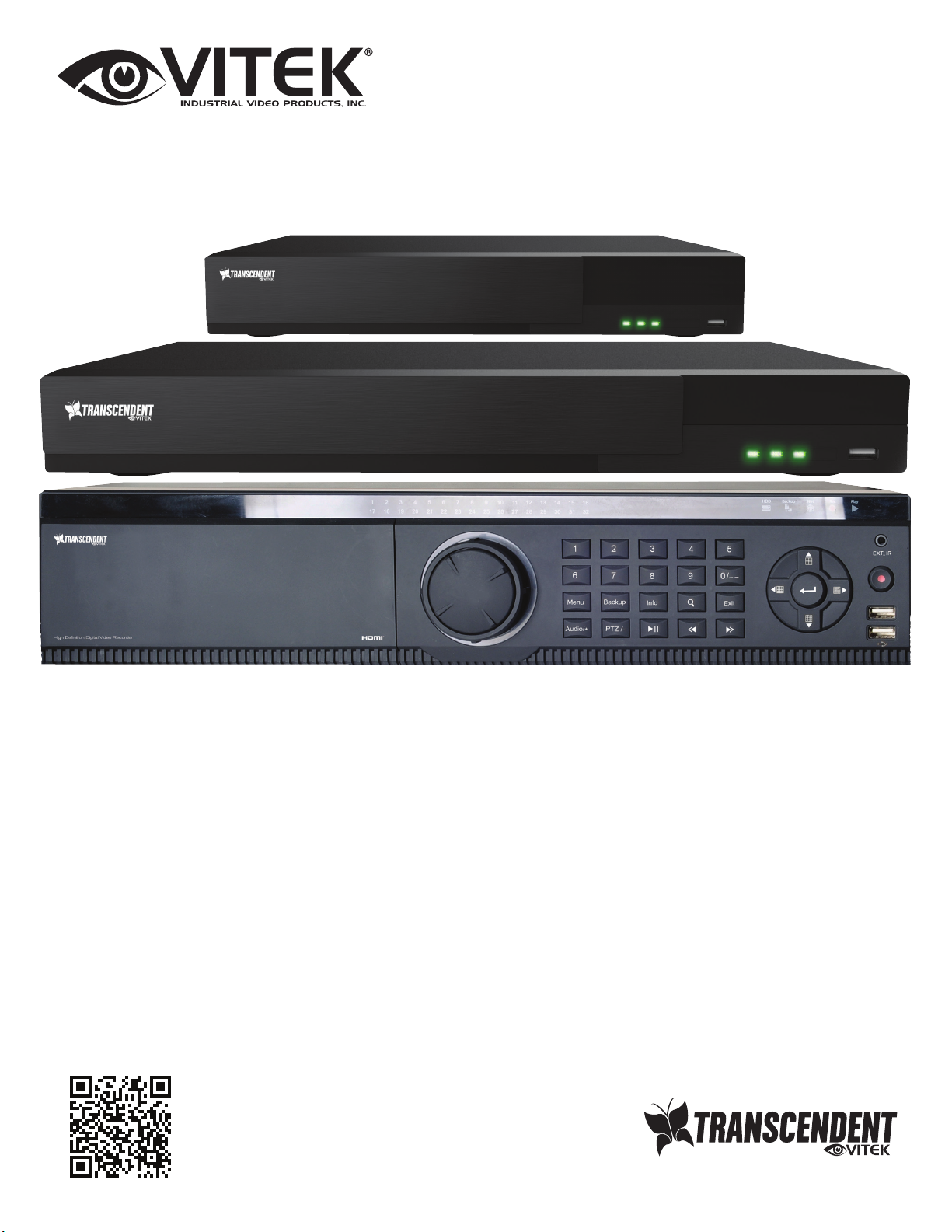
VT-TTAR Series
Transcendent Series 4, 8, 16, and 32 Channel
HD-TVI/AHD/960H/IP Digital Video Recorders
QUICK START GUIDE
FEATURES:
● 4, 8, 16, or 32 Channel HD-TVI/AHD/960H BNC Inputs + IP Camera Support
● 1-Channel IP Camera Support (VT-TTAR410 / VT-TTAR810) / 4-Channel IP Camera Support (VT-TTAR1620 &
VT-TTAR3280)
● Simple plug and play, point-to-point connection from camera to DVR
● H.264 Compression
● HDMI, VGA, and BNC (Spot) Video Outputs
● 2-Way Audio
● PTZ Control over RS-485
● 4 Alarm inputs / 1 Alarm Output
● Pentaplex: Live Display / Record / Playback / Backup / Remote Access
● 1 Internal SATA2/SATA3 HDD Slot supporting up to 6TB (VT-TTAR410 / VT-TTAR810) / 2 Internal SATA2/SATA3
HDD Slots supporting up to 12TB (VT-TTAR1620) / 8 Internal SATA2/SATA3 HDD Slots supporting up to 48TB
(VT-TTAR3280) /
● Applications for iOS & Android
● Remote Viewing over the Internet via Web Browser or LAN
● Mac OS® Client & CMS Central Management Software Included
● Supports both Dynamic and Static IP Addresses
● Control locally via USB Mouse or IR Remote control
PLEASE NOTE:
Complete User Guide, Software, Tools, and Updates
are available online. Scan the QR Code or visit:
http://www.vitekcctv.com/Downloads
Page 2
SETUP & CONFIGURATION:
1. Notes
● Please read this instruction carefully for correct use of the product and preserve it for reference purposes.
● This manual is suitable for 4/8/16 CH HD TVI Hybrid DVR. All the examples and pictures used here are for
reference only.
● There may be several technically incorrect places or printing errors in this manual. The updates will be added into
the new version of this manual. The contents of this manual are subject to change without notice.
● To prevent electric shocks and risk of fire hazards, do NOT use other than specific power source.
2. Check Package Contents
Please confirm that the device and all accessories are included in the package. If there is any damage, shortages
or defects, please contact your dealer immediately.
1) Transcendent Series DVR
2) IR Remote Control
3) Quick Start Guide
4) Power Supply
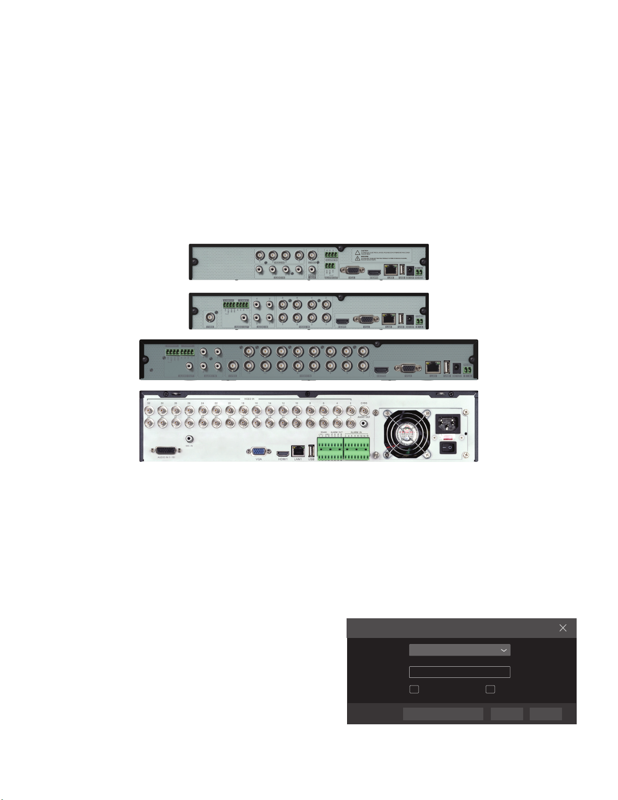
3. Rear Panel Connections
VT-TTAR1620 Rear Panel Connections
VT-TTAR3280 Rear Panel Connections
5) Rack Ears (16 & 32 Channel Models)
6) HDD Screws
7) SATA Cables
8) USB Mouse
VT-TTAR410 Rear Panel Connections
VT-TTAR810 Rear Panel Connections
4. Startup & Shutdown
● Startup:
1 Connect the monitor and the power.
2 The device will boot and the power indicator will display blue.
3 A wizzard window will pop up.
● Shutdown:
Go to “Main Menu” and then select “Shutdown” icon. This will bring up a shutdown window. The device will shut down
by clicking “OK” button. Then disconnect the power.
5. Login
You must configure the wizard when you start the DVR for the
first time. You can skip the settings of wizard next time. The
default username is admin and the password is set by you
when you configure the wizard for the first time. Click “Start”
Username
admin
Logi n
and select “Login”. This will take you to a login box. The
default username is admin; the default password is 123456.
Enter username and password and click “Login” button to go
to the main menu setup.
6. Analog Camera Connection
First connect the camera to the DVR. Then go to Start →
Password
Enter Password
Display Password Log In Automatically
LoginEdit Sec ur it y Question Cancel
Settings → Camera → Manage Camera → Signal Access Set
to checkmark the video mode. The actual signals input shall
correspond to the video mode. Please refer to User Manual
for details.
Page 3

7. Network Configuration & Adding IP Cameras
After you finish adding IP cameras, you can see the live images through the monitor of the DVR. The following will
mainly introduce how to add the IP cameras via LAN/WAN.
►LAN
1 Set the network of the DVR. Go to Start → Settings → Network →TCP/IPv4. Input IP address, subnet mask,
gateway, etc. If using DHCP, please enable DHCP in both the DVR and the router.
2 Go to Start → Settings → Network → Port. Input HTTP port (the default value is 80), server port (the default port is
6036).
3 Click “Apply” to save the settings.
TCP /IPv4
Por t
DDN S
IP Addr ess Set tings
Eth ern et Po rt 1 ( O n lin e )
Obta in an IP add ress au tomat icall y
IP Addre ss
Subn et Mask
Gate way
Obat in DNS se rver ad dress a utoma tical ly
Pref erred D NS
Alte rnate D NS
E-m ail
192 . 16 8 . 1 . 2
0 . 0 . 0 . 0
192 . 16 8 . 1 . 1
192 . 16 8 . 1 . 1
0 . 0 . 0 . 0
UPn P Net work St atus
NAT
4 Go to Start → Settings → Camera → Add Camera. The DVR will automatically refresh the cameras searched. The
IPC which supports the Onvif protocol may be added manually. If the IPC searched is not in the same local
network as the DVR, you should select the device and click to modify the IP address.
Edi t IP
CE :98 : 23 :75 :3 5 :22
192 .1 68 . 1 . 45
255 . 25 5 . 255 . 0
192 .1 68 . 1 . 1
admi n
OK Can cel
Qu ick ly A dd
M anu all y Ad d
No.
IP Addr ess
1
192. 168.2 .45
Sele cted: 1 /1
Rem ain Ba nd wid t h: 10 / 10 M b
80
Ad d Cam er a
EditPort
Subn et Mask
255. 255.25 5.0
Defa ult Pas sword
Prot ocol Mode l
XXXXXX
Add
Versi on
4.0. 0.1.b eta1
Canc el
Mac Add ress
IP Addr ess
Subn et Mask
Gate way
User name
Pass word
5 Checkmark the device you want to add and then click “Add” button. The DVR will automatically refresh the cameras
and return to “Edit Camera” interface. “Online” status means connecting the device successfully and you will see
the live image. You may select the added device and click to modify channel, IP address, ect.
Edi t Camer a
IP Cam era 1
192 .1 68 . 1 . 58
80
XXX
XXX
admi n
Disp lay Pas sword
OKTest Can cel
No. Came ra Name
1
2
[A01 ]Came ra1
3
[A02 ]Came ra2
4
[A03 ]Came ra3
5
[A04 ]Came ra4
Edi t Camer a
IP Addr ess
192. 168.1 .45IP Came ra 1
Edi t Camer a GroupSig nal Acce ss Set
Stat us
Port
Onli ne
80
Prot ocol Mode l
XXX
Sear ch Came ra
XXX
Prev iew
Dele teEdit
Came ra Name
IP Addr ess
Port
Prot ocol
Mode l
User name
Pass word
►WAN
1 Set the network of the DVR. Go to Start → Settings → Network → TCP/IPv4. Input static IP address or enable
PPPoE and then input the user name and password received from your ISP.
2 Go to Start → Settings → Camera. Click “Add Camera” or behind the column of the search camera and select
“Manually Add” to add the IP cameras. Input IP address, server port, username and password of the IP camera.
The IP camera must be connected over WAN. And here the IP address of the IP camera must be a WAN IP
address.
8. UPnP
You can use the UPnP function to enable the fast connection of the device to
WAN via a router without port mapping.
1 Go to Start → Settings → Network → UPnP, and enable UPnP and then
click “Apply” button to save.
2 Enable the UPnP function in the router.
3 Click “Refresh” button to refresh the UPnP status. If the UPnP status were
still “Invalid UPnP” after refreshing it for several times, the port would be
wrong. Please change the mapping type to “Manual” and then click to
modify the port until the UPnP status turns to “valid UPnP”.
TCP/ IPv 4
UPn P
Ena ble
Por t Type
HTT P Port
Ser ver Por t
RTSP P ort
Port UPnP
Aut oMap Typ e
Ext ernal P ort
80
603 6
554
E-mai l NAT Ne tw ork Sta tu s
DDNS
Ext ernal Ad dress
Por t
UPn P Status Ed it
80183 .17.2 54.19 Valid U PnP
Valid U PnP
603 6183 .17.2 54.19
Inv alid UP nP
554
Ref resh App ly
Page 4

9. NAT
► NAT Settings
1 The DVR shall be powered on and connected to the network.
2 Go to Start → Settings → Network → TCP/IPv4. You can obtain the
IP address, subnet mask and gateway automatically. You can also
manually enter them according to the actual network situation.
Please make sure the network segment is the same as that of the
network which is used.
3 Set the preferred or alternative DNS Server. Click “Apply” to save
the parameters.
4 Go to Start → Settings → Network → NAT tab. Enable NAT and
select the NAT Server (The default NAT Server is nat.autonat.com). Click “Apply” to save the parameters.
► NAT Access
After finishing the NAT settings, you can input www.autonat.com in
the IE address bar and then press enter to go to the following interface. If this is the first time accessing the NAT, you need to download
and install the ActiveX according to the popup tips. After installing
ActiveX successfully, it will pop the login box.
TCP/ IPv 4
NAT
Ena ble
NAT Se rve r
Port UPnP NAT
E-mai l Netwo rk S ta tus
DDNS
nat .auto nat.c om
Enter dev ic e se ri al numb er
Enter Use rn am e
App ly
Device Serial Number: Click on the menu bar at the bottom of the
live interface to check the serial number or go to Start → Settings →
Enter Pas sw or d
Network → Network Status to check the serial number of the DVR).
Username: The username of the DVR. (Default: admin)
Logi n
Password: The password of the DVR. (Default: 123456)
10. Manual Recording
Before recording, please install and format a HDD. In the live interface you can see the menu toolbar. Click to start
recording. Click it again to stop recording. You can also click to check the status of the recording.
11. Playback
►Instant playback
Click “Instant Playback” in the right-click menu of the camera’s
preview window to select or drag the playback progress bar to
change the playback time to play back the recording.
►General playback
Click on the tool bar at the bottom of the live preview interface or click Start → Playback to go to the playback interface
as shown below. You can also add the playback cameras
manually. Click in the playback window to pop up the “Add
Camera” window. Check the cameras in the window and then
click “Add” to add playback camera. The record files of the
added playback camera will be played in the playback interface.
28492 CONSTELLATION ROAD VALENCIA, CA 91355
WWW.VITEKCCTV.COM
Version 2.0
March 2017
 Loading...