

Vitek Vt-SRL908, Vt-SRL916, Vt-SRL904 Quick Start Manual
1
Installation
6
Access to
the mobile
viewer
5
Network
Setting
•
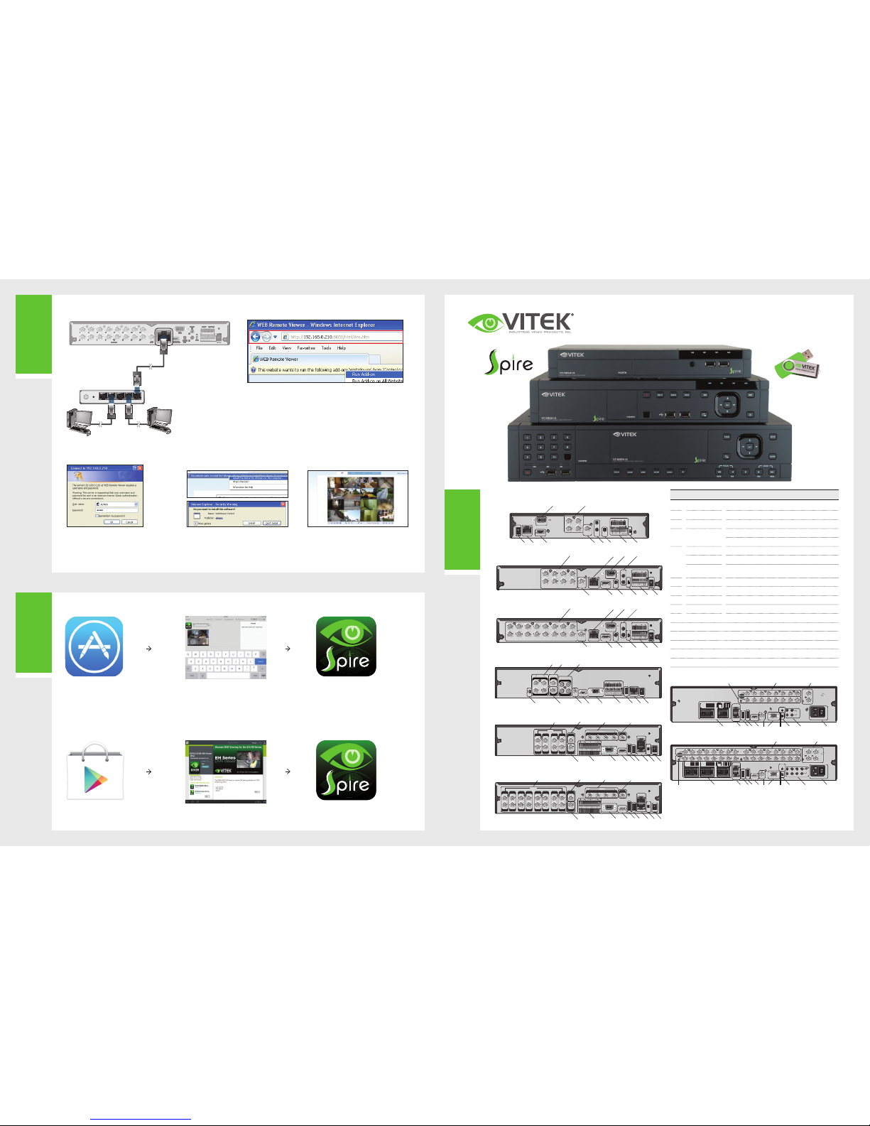
REAR VIEW
No. Name Description
A
VIDEO IN Video input te rminal for cam eras.
B
ETHERNET Network por t for connect ion to the Interne t, router or hub.
C
VGA VGA monitor video output port.
D
AUDIO IN
1/2 : Audio input ter minal that supp orts channe ls 1 and 2.
3/4 : Audio input te rminal that su pports chann els 3 and 4.
E
ALARM IN Alarm input s ignal port.
REL AY Relay Terminal output port.
RS485
Ports for com munication wi th external dev ices such as a PTZ
camera and sy stem keyboard.
F
DC 12V Power input po rt. Connect t o a 12V adaptor.
G
DIP Switch Switch to select a vi deo type or an out put type.
H
AUDIO OUT Port for speaker connection.
I
HD MONITOR HDMI (HD monitor) video output port
J
AUX Auxiliary Video Output
K
USB USB Input
L
eSATA Exter nal S ATA Por t
M
LOOP OUT Looping Video Outputs
N
SPOT Spot Video Output
O
POWER 120V Power Input / On /Off Switch
•
NETWORK CONNECTION
•
ACCESSING WITH THE BROWSE R
2.
When the logi n dialog appea rs, enter the us er name
and passwor d.
The default ID a nd password
- User name : ADM IN
- Password : 1234
NOTE: The User name and Passwo rd are case sen sitive.
3.
Click the upper warning bar to install the ActiveX
before enabling the add-in function.
4.
When the security warning window appears, click
<Insta ll>.
5.
When the ActiveX is installed completely, you will
see the live scr een.
For more infor mation about us ing the Web viewer, ref er to the
user manual.
1. Open the brows er and enter the I P address of the DVR , or enter the URL
address in the address bar.
ex) If using t he DDNS:
http://00115f123456.dvrlink.net:8080
If using an IP ad dress:
http://192.168.0.210:8080
For more infor mation about th e router and net work setting s, refer to the user
manual of the r espective pro duct.
HD MONITOR
VGA
AUX
DC 12V
ETHERNET
VIDEO IN
IN 1
IN 2
GND
IN 3
IN 4
NO
COM
NC
D+
D-
ALARM IN RELAYRS485
PAL
NTSC
3
1
7
5
11
9
15
13
4
2
8
6
12
10
16
14
AUDIO
IN
AUDIO
OUT
1/2
3/4
VGA
AUX
DC 12V
VIDEO IN
RS485
NTSC
3
1
7
5
11
9
15
13
4
2
8
6
12
10
16
14
AUDIO
IN
AUDIO
OUT
1/2
3/4
HD MONITOR
VGA
ETHERNET
IN 1
IN 2
GND
IN 3
IN 4
NO
COM
NC
D+
D-
ALARM IN RELAY
PAL
NTSC
AUDIO
IN
AUDIO
OUT
1/2
3/4
4WANRESETPWR 3 2 1
2
4
Local PC Local PC
Broadband r outer
or hub
•
HOW TO DOWNLOAD AND ACCESS THE IOS- SPECIFIC VIEWER
•
HOW TO DOWNLOAD AND ACCESS THE ANDROID-SPECIFIC VIEWER
DVR Viewer
DVR Viewer
1.
From your iPhone,
access App store
2.
Type "Spire DVR
Viewer" in th e Search
bar
3.
After Insta llation, sele ct
"Spire DVR Vie wer" again to
launch the app
Spire Series Quick Start Guide
4, 8, & 16 Channel 960H Digital Video Recorders
HD MONITOR
VGA
AUX
DC 12V
ETHERNET
VIDEO IN
IN 1
IN 2
GND
IN 3
IN 4
NO
COM
NC
D+
D-
ALARM IN RELAYRS485
PAL
NTSC
3
1
7
5
11
9
15
13
4
2
8
6
12
10
16
14
AUDIO
IN
AUDIO
OUT
1/2
3/4
I H G E F
A CB D
VT-SRL916
J
A B D
HD MONITOR
VGA
AUX
DC 12V
ETHERNET
VIDEO IN
IN 1
IN 2
GND
IN 3
IN 4
NO
COM
NC
D+
D-
ALARM IN RELAYRS485
PAL
NTSC
3
1
7
5
4
2
8
6
AUDIO
IN
AUDIO
OUT
1/2
3/4
H G E FI
C
VT-SRL908
J
ETHERNET
1
2
3
4
VIDEO IN
AUX
DC 12V
VGA
HD MONITOR
1/2
3/4
AUDIOINAUDIO
OUT
IN 1
IN 2
GND
IN 3
IN 4
NO
COM
NC
D+
D-
ALARM IN RELAYRS485
PAL
NTSC
H EF GIACB D
VT-SRL904
J
AUDIO IN
CH1
CH2
CH4
CH3
CH1
CH2
CH4
CH3
AUX
SPOT OUT
VIDEO IN VIDEO OUT
PAL
NTSC
HD MONITOR
DC 12V
ETHERNETUSB
RS-232
RELAY
ALARM IN
RS-485
485+
485-
NC2
GND
IN3
IN4
COM1
NO1
COM2
GND
232TX
232RX
IN1
IN2
VGA
AUDIO
OUT
B
A D
C FKIH EG
VT-SRE904
J
N
HD MONITOR
VGA
eSATA USB LAN(DOWNLINK)
WAN(UPLINK)
VIDEO IN
RS-232
RELAY
ALARM IN
485+
485-
GNDGND
NC2
GND
IN3
IN4
COM1
NO1
COM2
GND
232TX
232RX
IN1
IN2
RS-485
AUDIO
OUT
AUX
SPOT OUT
AUDIO
IN 1
AUDIO
IN 2
AUDIO
IN 3
AUDIO
IN 4
AUDIO IN
7856341
2
P
A
L
N
T
S
C
DC 12V
VT-SRE908
B
A
D
C FKI
H
E GL
J
N
HD MONITOR
VGA
eSATA USB LAN(DOWNLINK)
WAN(UPLINK)
VIDEO IN
RS-232
RELAY
ALARM IN
485+
485-
GNDGND
NC2
GND
IN3
IN4
COM1
NO1
COM2
GND
232TX
232RX
IN1
IN2
RS-485
AUDIO
OUT
AUX
SPOT OUT
AUDIO
IN 1
AUDIO
IN 2
AUDIO
IN 3
AUDIO
IN 4
AUDIO IN
1516131411
12
9107856341
2
P
A
L
N
T
S
C
DC 12V
VT-SRE916
B
A D
C FKI
H
E GL
J
N
RELAY
NO3
NO1
COM3COM1
COM4COM2
NC4NC2
IN5 IN1
IN6 IN2
GNDGND
IN7 IN3
IN8 IN4
GNDARI
ALARM IN
RELAY
NO7
NO5
COM7COM5
COM8COM6
NC8NC6
IN3 IN9
IN14IN10
GNDGND
IN15IN11
IN16IN12
GND
PANIC
ALARM IN
RS-485_1
ALARM OUT
RS-485_2
D+ D+
D- D-
GNDGND
RX TX
AO5AO1
AO6AO2
GNDGND
AO7AO3
AO8AO4
RS-232
LAN
(DOWNLINK)
WAN
(UPLINK)
eSATAUSB HD MONITOR AUX VGA
NTSC
PAL
1 2 3 4 5 6 7 8 9 10 11 12 13 14 15 16
1 / 2
1 / 2 5 / 6 9 / 10 13 / 14
3 / 4 7 / 8 11 / 12 15 / 16
AUDIO OUT
AUDIO IN
ON
OFF
100-240V - 50/60 Hz
SPOT 1
SPOT 2
SPOT 3
SPOT 4
VIDEO IN
LOOP OUT
RELAY
NO3NO1
COM3COM1
COM4COM2
NC4NC2
IN5 IN1
IN6 IN2
GNDGND
IN7 IN3
IN8 IN4
GNDARI
ALARM IN
RELAY
NO7NO5
COM7COM5
COM8COM6
NC8NC6
IN3 IN9
IN14IN10
GNDGND
IN15IN11
IN16IN12
GND
PANIC
ALARM IN
RS-485_1
ALARM OUT
RS-485_2
D+ D+
D- D-
GNDGND
RX TX
AO5AO1
AO6AO2
GNDGND
AO7AO3
AO8AO4
RS-232
LAN
(DOWNLINK)
WAN
(UPLINK)
eSATAUSB HD MONITOR AUX VGA
NTSC
PAL
1 2 3 4 5 6 7 8 9 10 11 12 13 14 15 16
1 / 2
1 / 2 5 / 6 9 / 10 13 / 14
3 / 4 7 / 8 11 / 12 15 / 16
AUDIO OUT
AUDIO IN
ON
OFF
100-240V - 50/60 Hz
SPOT 1
SPOT 2
SPOT 3
SPOT 4
VIDEO IN
LOOP OUT
RS-485_1
ALARM OUT
RS-485_2
D+
D+
D-
D-
GNDGND
RX TX
AO3AO1
AO4AO2
GNDGND
RS-232
LAN
(DOWNLINK)
WAN
(UPLINK)
eSATAUSB HD MONITOR AUX VGA
NTSC
PAL
1 / 2 5 / 6
3 / 4 7 / 8
AUDIO OUT
ON
OFF
100-240V - 50/60 Hz
SPOT 1
SPOT 2
AUDIO IN
1 2 3 4 5 6 7 8
VIDEO IN
LOOP OUT
RELAY
NO3
NO1
COM3COM1
COM4COM2
NC4NC2
IN5 IN1
IN6 IN2
GNDGND
IN7 IN3
IN8 IN4
GNDARI
ALARM IN
VT-SRP908
A NM
FDIK L HB GCE J
RELAY
NO3
NO1
COM3COM1
COM4COM2
NC4NC2
IN5 IN1
IN6 IN2
GNDGND
IN7 IN3
IN8 IN4
GNDARI
ALARM IN
RELAY
NO7
NO5
COM7COM5
COM8COM6
NC8NC6
IN3 IN9
IN14IN10
GNDGND
IN15IN11
IN16IN12
GND
PANIC
ALARM IN
RS-485_1
ALARM OUT
RS-485_2
D+ D+
D- D-
GNDGND
RX TX
AO5AO1
AO6AO2
GNDGND
AO7AO3
AO8AO4
RS-232
LAN
(DOWNLINK)
WAN
(UPLINK)
eSATAUSB HD MONITOR AUX VGA
NTSC
PAL
1 2 3 4 5 6 7 8 9 10 11 12 13 14 15 16
1 / 2
1 / 2 5 / 6 9 / 10 13 / 14
3 / 4 7 / 8 11 / 12 15 / 16
AUDIO OUT
AUDIO IN
ON
OFF
100-240V - 50/60 Hz
SPOT 1
SPOT 2
SPOT 3
SPOT 4
VIDEO IN
LOOP OUT
RELAY
NO3NO1
COM3COM1
COM4COM2
NC4NC2
IN5 IN1
IN6 IN2
GNDGND
IN7 IN3
IN8 IN4
GNDARI
ALARM IN
RELAY
NO7NO5
COM7COM5
COM8COM6
NC8NC6
IN3 IN9
IN14IN10
GNDGND
IN15IN11
IN16IN12
GND
PANIC
ALARM IN
RS-485_1
ALARM OUT
RS-485_2
D+ D+
D- D-
GNDGND
RX TX
AO5AO1
AO6AO2
GNDGND
AO7AO3
AO8AO4
RS-232
LAN
(DOWNLINK)
WAN
(UPLINK)
eSATAUSB HD MONITOR AUX VGA
NTSC
PAL
1 2 3 4 5 6 7 8 9 10 11 12 13 14 15 16
1 / 2
1 / 2 5 / 6 9 / 10 13 / 14
3 / 4 7 / 8 11 / 12 15 / 16
AUDIO OUT
AUDIO IN
ON
OFF
100-240V - 50/60 Hz
SPOT 1
SPOT 2
SPOT 3
SPOT 4
VIDEO IN
LOOP OUT
RELAY
NO3
NO1
COM3COM1
COM4COM2
NC4NC2
IN5 IN1
IN6 IN2
GNDGND
IN7 IN3
IN8 IN4
GNDARI
ALARM IN
RELAY
NO7
NO5
COM7COM5
COM8COM6
NC8NC6
IN3 IN9
IN14IN10
GNDGND
IN15IN11
IN16IN12
GND
PANIC
ALARM IN
RS-485_1
ALARM OUT
RS-485_2
D+
D+
D-
D-
GNDGND
RX TX
AO5AO1
AO6AO2
GNDGND
AO7AO3
AO8AO4
RS-232
LAN
(DOWNLINK)
WAN
(UPLINK)
eSATAUSB HD MONITOR AUX VGA
NTSC
PAL
1 2 3 4 5 6 7 8 9 10 11 12 13 14 15 16
1 / 2
1 / 2 5 / 6 9 / 10 13 / 14
3 / 4 7 / 8 11 / 12 15 / 16
AUDIO OUT
ON
OFF
100-240V - 50/60 Hz
SPOT 1
SPOT 2
SPOT 3
SPOT 4
VIDEO IN
LOOP OUT
AUDIO IN
VT-SRP916
A N
FDIKL HB GCE JM
Visit www.vitekcctv.com for the latest updates
inluding: Product Information, Software, Firmware,
and Product Literature.
* Complete User' s Manual
can be found on the in cluded
USB Flash Drive.
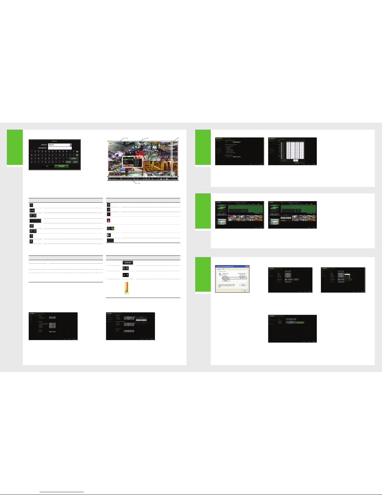
1.
From your Androd
phone, ope n the Play
Store
2.
Type "Spire DVR
Viewer" in th e Search
bar
3.
After Insta llation, sele ct
"Spire DVR Vie wer" icon to
launch the app
3
Recording
5
Network
Setting
4
Search
2
Getting
Started
•
AUTOMATIC RECORDING SETTING
1. Press [MENU] on the remote control, and use the
direction b uttons to selec t <RECORD SETU P> and
press [ENTER].
Alternatively, you can select <MENU> - <RECORD
SETUP> from the status bar.
2. S et <RECORD SETU P MODE> to <AUTO
CONFIGURATION>.
3. S elect "Automatic Re cord Congura tion Mode".
•
ALWAYS HIGH VIDEO QUALI TY : Recordin g will
proceed in th e best quality r egardless o f the event
at all times.
As this option w ill always make re cording in the
best quality, the recording period is the shortest
compared to the other record modes.
•
MOTION RECORD : Recording will proceed only if
a motion is detected.
•
TIME SEARCH
1.
From the <SEA RCH> menu, sele ct <TIME SEARCH>.
2.
Specify th e search date an d time from the cal endar
in the left corner of the screen.
3.
You can identify the type of the recording data by the color
in the bar.
•
Yellow Green (PRE R ECORDING) : The p re-record ing
is perform ed on the record ing data after yo u set
the <PRE RECORDING TIME> from <OPERATION
MODE>.
•
Green (Continuous) : The continuous recording is
performed on the recording data.
•
Red (Alarm) : T he alarm event re cording is
performed on the recording data.
•
Blue (Motion ) : The motion event r ecording is
performed on the recording data.
•
Yellow (Panic) : The p anic manual re cording is
performed on the recording data.
4.
Click to move to a des ired start t ime in the time
bar, or use the but tons at the botto m of the
status bar to m ake search.
5.
Select an ite m to play and click <P LAY>.
Click to
move to a desired time, or simply double-click a desired
time in the time bar to play the video data on that time.
•
For details on t humbnail searc h and event
search, re fer to the user man ual.
•
NETWORK CONNECTIO N SETTING
TO CONFIGURE THE NET WORK SETTINGS
1.
Connect the DVR to the router.
2.
Connect the [ WAN/UPLINK )] port of the rou ter directly to
the xed IP LAN ca ble, or connect it to th e ADSL modem.
5.
When the netwo rk congurati on is complete, proc eed
with the DDNS settings.
From the main me nu of the DVR, move to <SYS TEM
SETUP> - <NE TWORK> - <DDN S>.
6.
Rename the DVR. (The default name of the DVR is the
MAC address of t he DVR.)
Enter a desir ed DVR name (combi nation of chara cters
and numbers).
1.
From the main me nu of the DVR, move to <SYS TEM
SETUP> - <NE TWORK> - <IP SE TUP>.
2.
Use DHCP to get a n IP address from t he router, or
manually en ter an IP addres s that falls withi n the
private IP ra nge provided by th e router.
•
IP ADDRESS : 192.168. 0.123 (enter the network
IP address.)
•
GATEWAY : 192.168.0.1 (enter the ga teway
address.)
•
SUBNET MAS K : 255.255.25 5.0 (type the sub net
mask.)
•
1ST, 2ND DNS SERVER : 168.126.6 3.1 (enter the
address of a DN S server.)
7.
When done, click <DDNS REGISTRATION TEST>
and <DDNS CON NECTION TEST> in this o rder.
If you receive a s uccess messa ge. Check the
DVR address a nd click <APPLY> at the bot tom.
8.
Check the DVR ad dress and the Web s ervice
port in the ne twork settin gs to make sure that
any Internet-connected PC can access the DVR.
9.
If you type "mydv r" for the DVR name f rom the
DDN item, the ad dress of the Web vi ewer is
"http://mydvr.dvrlink.net: 8080".
•
ALARM RECO RD : Recording w ill proceed
only if an alar m event occurs.
•
MOTION/ALA RM RECORD : Recor ding will
proceed onl y if a motion is dete cted or an
alarm event oc curs.
•
INTENSIVE MOTION RECORD : Recording
will be perfo rmed in a low quali ty. However,
the quality w ill switch to high i f a motion event
is detected.
•
INTENSIVE A LARM RECORD : Re cording will
be perform ed in a low qualit y. However, the
quality wil l switch to high if an a larm event
occurs.
•
INTENSIVE MOTION/ALARM RECORD :
Recording w ill be perform ed in a low qualit y.
However, the quali ty will switch to hi gh if an
alarm event oc curs or a motion i s detected.
4. Cl ick <APPLY>.
3.
When done, con gure the port for warding for
the RTSP and Web S ervice por ts by clicking Por t
Forwarding.
4.
Click <PORT FO RWARDING> for eac h. You will see
the conrmat ion message. Cli ck <APPLY> and exit
the menu.
5.
The network settings of the DVR are complete.
Note:
Some router models may not support UPNP.
If you see a failu re message aft er clicking <PO RT FORWARDING>,
refer to the user m anual of the router a nd congure the po rt
forwarding settings manually.
Item Description
Access the DVR 's menu; Search , Archiving, Sy stem Setup, Rec ord Setup, Log
Out, and Shutdown.
Show the ID of the u ser who has curr ently logged in .
Edit the scre en layout to show the s tatus bar and tim eline at all time s or only
when the mouse cursor hovers on the status bar/timeline.
Used to selec t a split mode.
Auto Sequenc e Mode.
Display or hide the OSD menus on the screen.
Move to the PTZ scr een. You can contro l the PTZ opera tions of a PTZ-comp liant
camera on the P TZ screen.
Move to the Zoom sc reen.
Item Description
Display the log list of the recent recording events.
Select the Audio input channel.
Start the emergency recording.
Blinks when th e event occurs. I t will not blink if no a ction to the event ha s been
set.
Click to view information about the event that occurred.
Check if network connection is made via an external PC or mobile device.
Click this to view the details of the concurrent users and to check the network
connection status.
Show the disk sp ace informati on. If you have set the d isk overwrite m ode, it will
be displayed "OW" (Over Write) from the start point of the overwriting.
Display the current time and date.
•
LANGUAGE SETTING
•
DATE/TIME SETTING
•
STAT US BA R
BESIDES THE RE MOTE CONTROL BUT TONS, YOU CAN ALSO U SE THE BUTTONS O N THE BOTTOM STATUS BAR TO CO NTROL THE DVR.
1. Press [SE TUP] on the remote c ontrol, or sel ect <MENU> - <SYSTE M SETUP>
from the stat us bar.
2. From <SYSTEM SE TUP> - <DISPLAY>, sele ct <OSD>.
3. Select a preferred language.
4. Click <APPLY>.
1. Press [SETU P] on the remote co ntrol, or selec t <MENU> - <SYSTEM SE TUP>
from the stat us bar.
2. Fr om <SYSTEM SETUP> - < SYSTEM>, select <DATE /TIME>.
3. Specif y the display format of the current time and date.
•
As the existing d ata in the same tim e and date will be de leted if duplic ates
are found, bac k up the existing da ta for later use.
4. Cl ick <APPLY>.
Item Description
Channel No Display the number of the current channel.
Play Start p laying the video of th e selected chan nel from the speci ed time.
Zoom Move to the Digital Zoom.
Snapshot Capture
Capture the cu rrent live vide o and save it in the .jp eg format.
•
Then, you can sa ve the captured vi deo in the HDD or
export it to an ex ternal USB mem ory device.
Item Description
Timeline Date
Display the date of the current timeline.
Click this to select a desired date of the timeline.
Zoom in/out the
timeline
Expand or collapse the timeline.
Navigation
through Timeline
Move to the previous or next point of time in the timeline.
You can also use the m ouse wheel to navi gate through th e
timeline.
Timeline Bar
Represent t he recorded da ta. The color of e ach bar
indicates:
~
Green : Continuous Recording
~
Red : Alarm Re cording
~
Blue : Motion Recording
~
Yellow: Panic Recording
•
Double- click the timeli ne to move to the Playbac k mode. Drag and d rop it to
make backup or eve nt search for the spe cied area.
Video Window Quick Menu
Status Bar
Time
line
•
TIMELINE
•
QUICK MENU
•
LOG IN
•
LIVE SCREEN
1.
When the syste m starts, the l ogin screen ap pears.
2.
Select the us er ID and enter the p assword.
The default user ID is “ADMIN”; the default password is “1234”.
3.
Click <OK>.
•
For safe and se cure use of the prod uct, change the p assword after p urchasing.
 Loading...