

Page 1
SpireHD Quick Start Guide
16 Channel SpireHD Series Real-time CVBS / HD-TVI /
AHD and IP Digital Video Recorders
VT-SHP5016AN
1
Installation
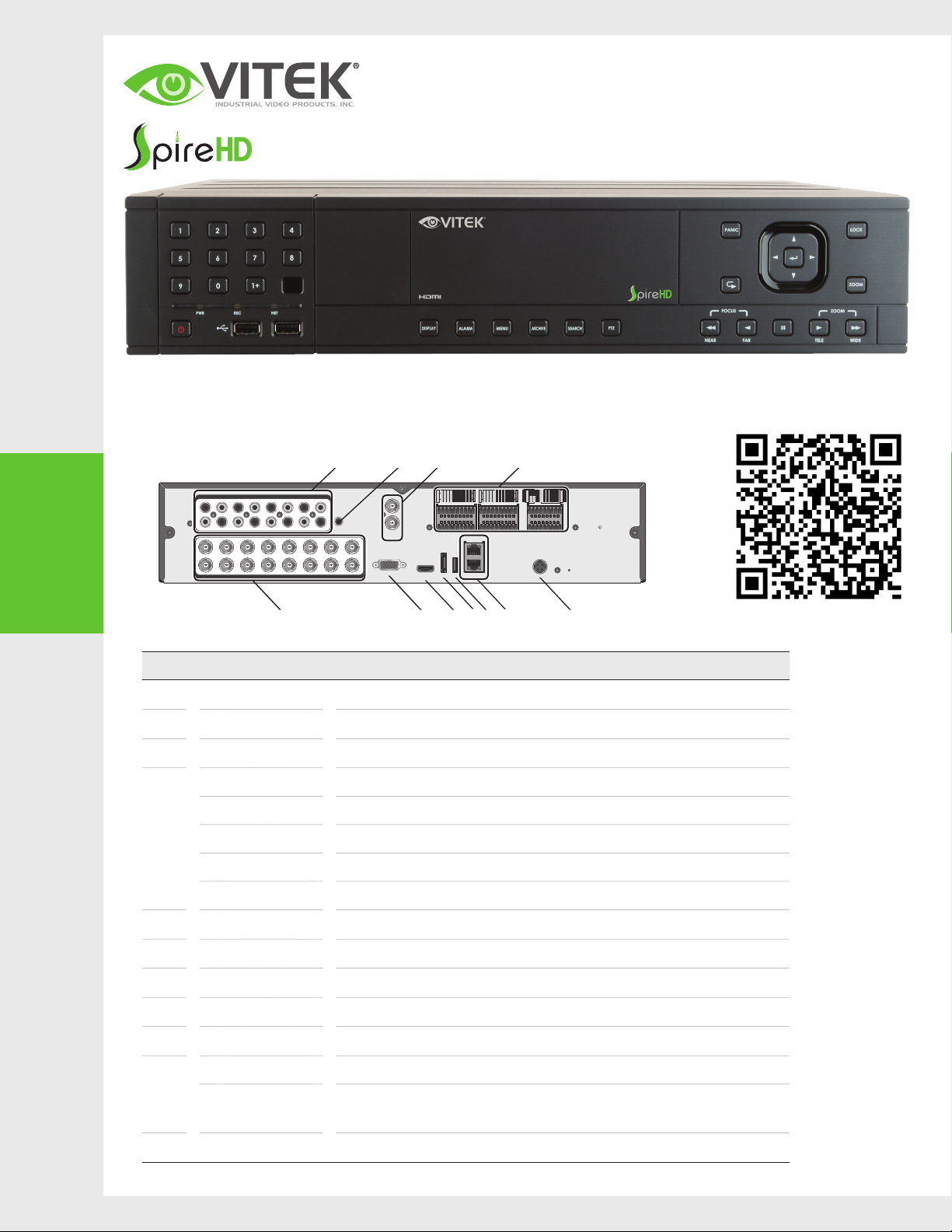
FRONT PANEL
•
REAR PANEL
•
AUDIO IN
9 11 13 157531
1 3 5 7 9 11 13 15
2 4 6 8 10 12 14 16
10 12 14 168642
VIDEO IN
A F G H I KJ
No. Name Description
A
B
C
VIDEO IN Video input te rmin al for c amer as.
AUDIO IN Port for audio input.
AUDIO OUT Port for speaker connection.
ALARM IN Alar m input s igna l por t.
ALARM OUT Alar m out signal port. O.C. (Pull ed up to 5V via 10KOhm)
B C DE
AUDIO
OUT
SPOT
OUT
VGA
HD
MONITOR
Visit www.vitekcctv.com for the latest updates
inluding: Product Information, Software, Firmware,
and Literature. FULL MANUAL available here:
D-
ARI
NO5
NO1
RELAY
RELAY
IN5 IN1
IN6 IN2
IN7 IN3
IN8 IN4
NO7
NO3
NC4 NC2
GND GND
GND
COM4COM2
COM3COM1
WAN(UPLINK)
USB
LAN(DOWNLINK)e-SATA
D+
PANIC
NC8 NC6
IN13 IN9
IN14 IN10
IN15 IN11
IN16 IN12
GND GND
GND
COM8COM6
COM7COM5
RS-232
D-
D+
RS-485_2
RX TX
RS-485_1
AO5 AO1
AO6 AO2
AO7 AO3
AO8 AO4
GND GND
GND GND
ALARM OUT
DC12V
D
E
F
G
H
I
J
K
RE L AY Relay Terminal output port.
RS485 Por ts for commu nicat ion with exte rnal d evice s such a s PTZ ca mera and sys tem keyb oard .
RS232 Conne ctio n ports for si gnal c able s to external d evice s such a s PTZ ca mera, POS and ATM devic es.
SPOT OUT Exclusive port for S POT out put only. (Connect to a T V moni tor.)
VGA VGA monitor video output port.
HD-MONITOR HD monitor video output port.
e- S ATA Connection port for external eSATA storage.
USB Used for connecting USB storage or mouse.
WAN(UPLINK) Networ k por t for connection to the Internet, route r or hub.
LAN(DOWN LINK)
Port for connecting the dedicated network device.
Do not share it with other devices.
DC 12V Power input port.
Page 2
2
Getting
Started
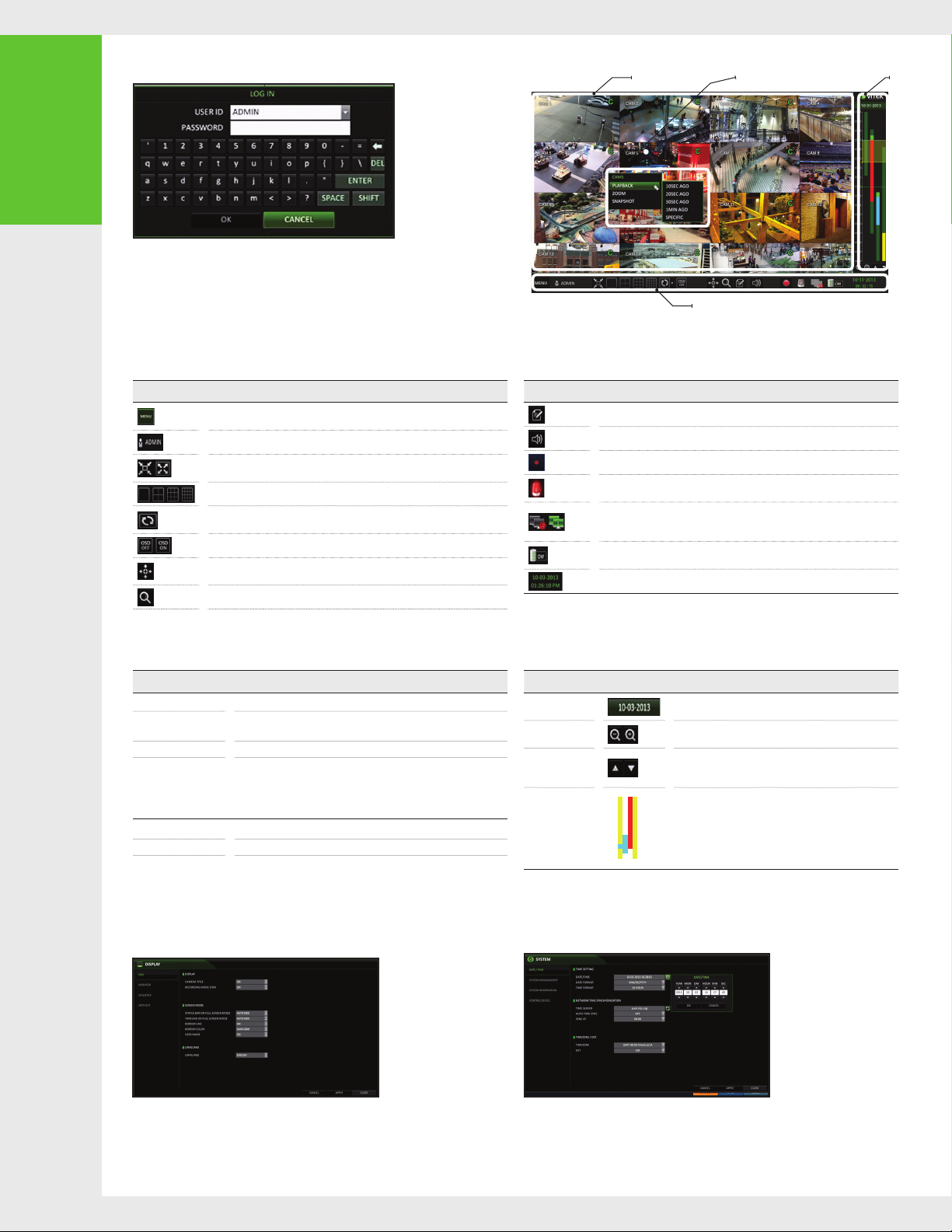
LOG IN
•
When the system sta rts , the login sc reen appear s.
1.
Select the u ser ID and ente r the password .
2.
The def ault user ID is “ADMIN ”; t he default password is “1234”.
Click < OK>.
3.
•
For safe and secure use of the product , chan ge the p asswor d afte r purchasing.
LIVE SCREEN
•
Video Window Q uick Menu
Status Bar
Time
line
STATUS BAR
•
Item Description
QUICK MENU
•
Item Description
Channel No Displ ay the nu mber of t he cur rent channe l.
Play St art p laying the vid eo of th e selected c hannel from t he spe cified time .
Zoom Move to th e Digital Zoom.
Snapshot Capture
Chang e Cam Chang e to a Dif ferent Camera
Calib ration To Cente r Came ra in Image
BESIDES THE RE MOTE CONTRO L BUTTONS, YOU CAN AL SO US E THE BUTTONS ON THE BOTTOM S TATUS BAR TO CONTROL T HE DVR .
Acce ss the DVR's me nu; S earc h, Archiving, Sys tem Se tup, Record Setup , Log
Out, and Shu tdown .
Show the ID of the user who is curr ently logge d in.
Edit th e scre en layout to show t he status ba r and timeline at all times or on ly when
the mouse cursor hovers on the status bar/timeline.
Select a split mode .
Auto Sequence Mode.
Displ ay or hide the OS D menus o n the sc reen .
PTZ Contro l. You can c ontr ol the P TZ ope rati ons of a PTZ-co mpliant camera on
the PTZ screen.
Access the Zoom screen.
Capture the c urren t live video and s ave it in a .jpeg format .
•
You can save the captured snapshot to the HD D or
expor t it to an ex ternal USB memor y devic e.
Item Description
Displ ay the lo g list of recent recorded events .
Select the A udio input channel .
Start emergency recording.
Flashes when a n event occurs. It will not flash if no ac tion to the event has be en set .
Click t o view information about th e event t hat oc curred.
Check if a network connec tion is made via an exte rnal P C or mobile devi ce.
Click t his to vi ew the details of the concur rent us ers and to chec k the ne twork
connection status.
Shows the disk sp ace in forma tion . If you have set th e disk ove rwrite mode , it will
be displayed "O W" ( Over Write) from the star t point of the ove rwri ting .
Displ ay the current time an d date .
TIMELINE
•
Item Description
Timeline Date
Zoom in /out th e
timeline
Navigation
through Timeline
Timeline Bar
•
Double- click the time line to m ove to the Pl ayback mode. Drag and drop it to
make bac kup or eve nt sear ch for the s peci ed ar ea.
Displ ay the da te of the curre nt timeline .
Click t his to selec t a desired date of the timeline.
Expand or collapse the tim eline.
Move to th e previous or nex t poin t of time in the timelin e.
You can also use the m ouse wh eel to navigat e through the
timeline.
Represent the recorded data. The color of each bar indicates:
Green : C ontinuous Recor ding
~
Red : Ala rm Recording
~
Blue : Mo tion Recording
~
Yellow: Panic Recording
~
LANGUAGE SETTING
•
1. Press [SE TUP] o n the re mote contro l, or se lect <M ENU > - <SYSTE M SETUP> fr om
the st atus bar.
2. From < SYSTEM SETUP> - < DISPLAY >, select < OSD >.
3. Select a preferred language.
4. Click <APPLY>.
DATE/TIME SETTING
•
1. Press [ SET UP] on t he remote con trol , or sel ect < ME NU > - <SYSTE M SETUP>
from th e stat us bar.
2. From < SYSTE M SET UP> - <SYS TEM >, select < DATE/TIME>.
3. Specify the display form at of the curre nt time and date.
•
As the exi sting d ata in the same t ime and date will be del eted if dupli cate s
are foun d, bac k up the existing data fo r later use.
4. Click <APPLY>.
Page 3
3
Recording
4
Search
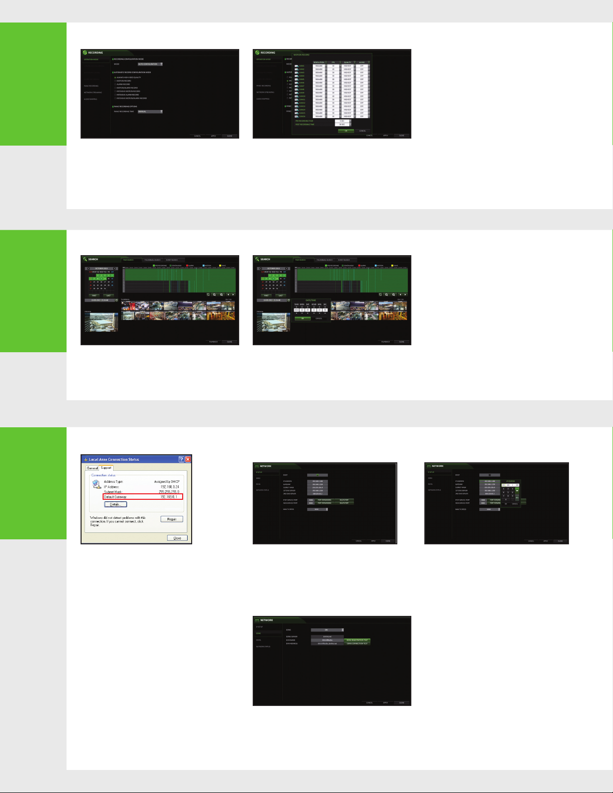
AUTOMATIC RECORDING SETTING
•
1. Press [ MENU] on t he rem ote control ,
and use the direction buttons to select
<R ECOR D SET UP> a nd press [E NTER ] .
Alter natively, you c an sel ect < MENU > - < RECORD
SETU P> fr om the s tatus bar.
2. Set < REC ORD SETUP M ODE > to < AUTO
CONFIGURATION>.
3. Select "Automatic Record Configuration Mode".
TIME SEARCH
•
From the < SEARCH > menu, select < TIME SEA RCH >.
1.
Specify the sear ch date and tim e from the calendar i n
2.
the lef t corner of the s creen.
You can ide ntif y the t ype of t he rec ording data by t he col or
3.
in the ba r.
•
ALWAYS HIGH V IDEO QUALIT Y :
Recording will proceed in the best quality
regardless of the event at all times .
As this optio n will always make recording in the
best qualit y, the recording period is t he shor tes t
compa red to the othe r reco rd modes.
•
MOTION RECO RD : Rec ording will pr ocee d only if
motion is detected.
•
Bright Green (PRE RECORDIN G) : Pre- rec ordin g is
performed a fter Pre- Reco rd time is set in Operation
mode
•
Green ( Con tinuous) : Shows tim e in continuous
record mode
•
ALAR M REC ORD : Re cording will p roce ed only
if an alarm event o ccur s.
•
MOTION/AL ARM R ECOR D : Recording w ill
proce ed only if moti on is det ected or an al arm
event oc curs .
•
INTENSIVE MOTIO N RECO RD : Recording will
be per forme d in a low qu alit y. Howeve r, the
quality will switc h to high i f motion event is
detected.
•
INTENSIVE ALARM REC ORD : Re cord ing will
be per forme d in a low qu alit y. Howeve r, the
quality will switc h to high i f an alar m event
occurs.
•
INTENSIVE MOTION/ALARM RECORD :
Recording will be performed in a low quality.
However, the qual ity wi ll swit ch to high if an
alarm event occurs or m otion is dete cted.
4. Click <APPLY>.
•
Red (Alarm) : Alarm event tri ggered recording
•
Blue ( Moti on) : Mo tion detec tion event tri ggered
recording
•
Yellow (Panic ) : Panic event re cording
Click t o move to a de sired star t time i n the time
4.
bar, or use t he but tons a t the bottom o f the
status bar to m ake search.
Select an item to play and cli ck < PLAY >.
5.
move to a desired t ime, o r simpl y doubl e-c lick a desire d
time in t he time bar to pl ay the vi deo data on at that time.
•
For det ails on t humbn ail search an d event
search, refer to th e user manual.
Click t o
5
Network
Setting
NETWORK CONNECTION SETTING
•
Connect th e DVR to the rout er.
1.
Connect th e [WAN/UPLINK)] po rt of the rout er dire ctly to
2.
the fixed IP LAN cable.
3.
When do ne, configu re the p ort fo rwarding for the RTSP
and Web Servi ce por ts by cl icki ng Por t Forw arding.
4.
Click < P ORT FORWARDING > for each . You will see
the confirma tion messag e. Click < APPLY> a nd exit t he
menu.
5.
The net work se ttings of th e DVR are c omplete.
Note :
Some ro uter models m ay not sup port UPNP.
If you see a failure mess age af ter cl icking < PORT F ORWARDIN G>,
refer to the use r manua l of the ro uter and conf igure t he por t
forwarding settings manually.
TO CONFIGURE THE NETWORK SETTINGS
1.
From the m ain menu of the DVR, move to < SYSTE M
SETU P> - < NETWORK> - < IP SETUP >.
2.
Use DHC P to get an IP addr ess fro m the router, or
manually enter an IP address that falls within the
private IP range provided by the router.
•
IP ADD RES S : 192.168 .0 .123 (enter the net work
IP address.)
When the network configuration is
5.
compl ete, p roce ed with the DD NS set tings.
From the m ain men u of the DV R, move to <S YSTEM
SETU P> - < NETWORK> - < DDNS>.
Rename the DVR . (The default nam e of
6.
the DVR i s the MAC address of the D VR. )
Enter a desired DVR na me (co mbination o f char acte rs
and numbers).
•
GATEWAY : 192.168.0 .1 (ent er the g ateway
address.)
•
SUBNET MASK : 255 .255. 255 .0 (t ype the subn et
mask.)
•
1ST, 2ND DN S SERVER : 168 .126.63.1 (en ter the
address of a DNS s erver.)
When do ne, click < DD NS REGIST RATION TEST>
7.
and < DDN S CONN ECTION TE ST> in this order.
If you receive a succe ss message. Chec k the DVR
address and click < APPLY> at the bottom.
Check the DVR a ddres s and th e Web ser vice port
8.
in the ne twork sett ings to m ake sure t hat any
Internet-c onne cted P C can a ccess the DV R.
If you type "mydvr" for t he DVR name from the
9.
DDNS item, t he addr ess of the Web viewer is
"http: //mydvr.dvrlink.net: 8080 ".
Page 4
5
DVR Viewer
DVR Viewer
Network
Setting
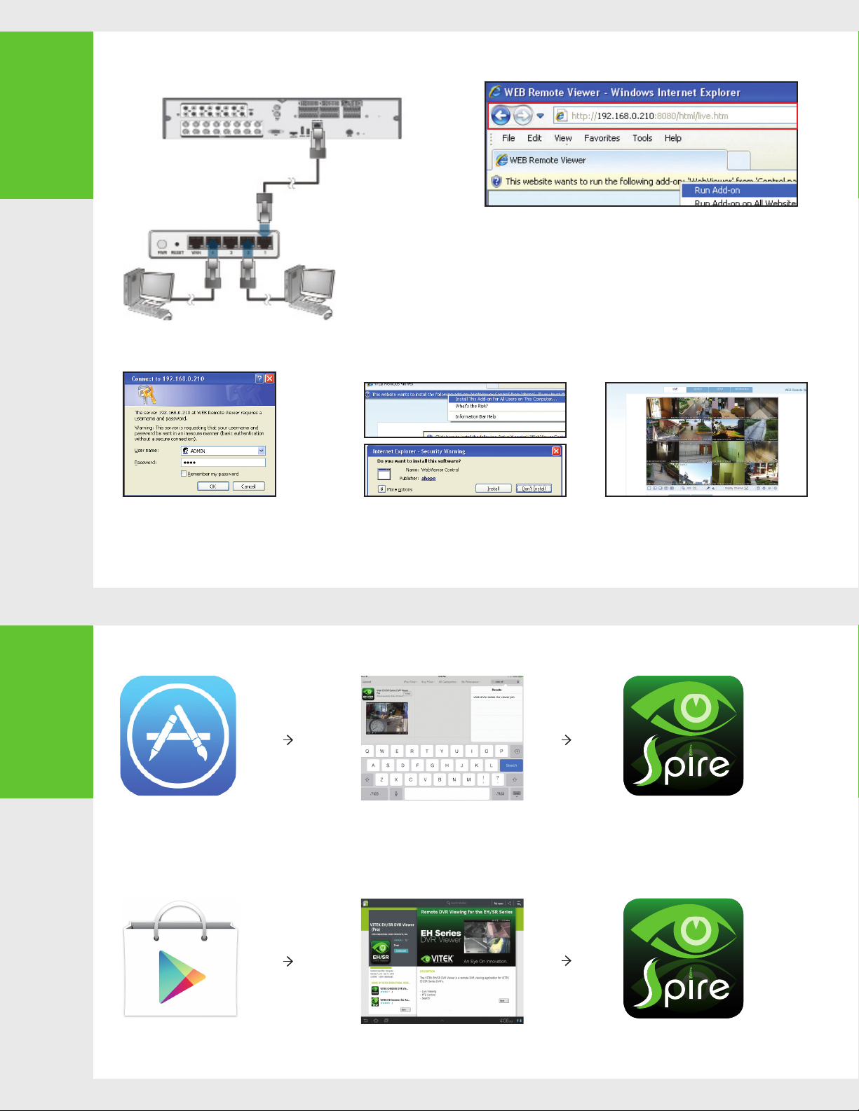
NETWORK CONNECTION
•
Broadband router
Local PC Local PC
or hub
ACCESSING WITH THE BROWSER
•
1. Open the browser and en ter th e IP addr ess of the DVR , or enter the URL addr ess
in the address b ar.
ex) If using the DDNS :
http://00115f123456.dvrlink.net :8080
If using an IP address :
http :// 192 .168 .0.210 : 80 80
For more information about the router and network settings, refer to the user
manual of the re spec tive produc t.
6
Access to the
mobile viewer
When the login dialog appears, enter the user name
2.
and password.
- User name : ADM IN
- Passwo rd : 1234
NOTE : The Usernam e and Pas sword are case sensitive.
HOW TO DOWNLOAD AND ACCESS THE IOS-SPECIFIC VIEWER
•
From your iPhone,
1.
access App store
HOW TO DOWNLOAD AND ACCESS THE ANDROID-SPECIFIC VIEWER
•
The def ault ID and password
Click t he upp er warning bar to install the A ctiveX
3.
before enabling the add-in function.
When the secu rity w arning window a ppears, cl ick
4.
<Install>.
Type "Spir e DVR
2.
Viewe r" in the Sear ch
bar
When the Act iveX is in stal led co mplet ely, you will
5.
see the live screen.
For more inform atio n about u sing the Web viewer, refe r to the user
manual.
After Insta llation, select
3.
"Spir e DVR Viewer" again to
launch t he app
From your Androd
1.
phone , open t he Play
Store
Type "Spir e DVR
2.
Viewe r" in the Sear ch
bar
After Installation, select
3.
"Spir e DVR Viewer" ic on to
launch t he app
 Loading...