

Vitek VT-SHE908A-6T, VT-SHE908A-3T, VT-SHE908A-12T, VT-SHE904A-6T, VT-SHE904A-3T Quick Start Guide
Page 1
1
Installation
SpireHD Quick Start Guide
4, 8, & 16 Channel SpireHD Series Realtime HD-TVI /
AHD / 960H Digital Video Recorders
* Complete User
Manual on included
USB Flash Drive.
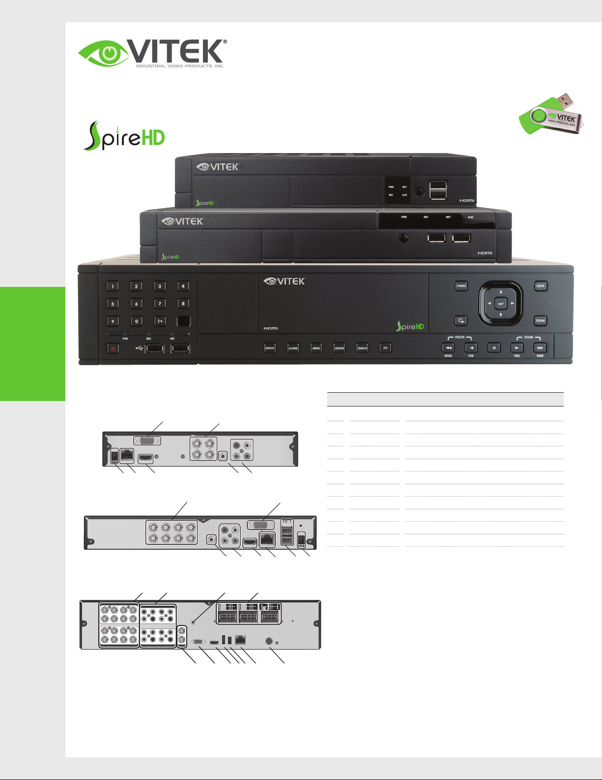
REAR VIEW
•
V T- SH E 904 A
DC 12V
VT-SHE908A
V T- SH P 916A
1 3 5 7
2 4 6 8
9 11 13 15
10 12 14 16
1
2
ETHERNET
VGA
HD MONITOR
J C
A
7
5
3
1
8
6
4
2
VIDEO IN
BA C D
VIDEO IN
VIDEO IN
AUDIO IN
1 3 5 7
2 4 6 8
9 11 13 15
10 12 14 16
AUDIO IN
AUDIO OUT
1
2
VGA
SPOT OUT
E F G H I J K
VIDEO IN
No. Name Description
VIDEO IN Video input terminals for Analpg/TVI/AHD cameras.
AF
3
4
AUDIO
OUT
3
1
4
2
AUDIO IN
BK G
F
RELAY
RS485
D-
D+
NC
NO
ETHERNET
RS-485_2
RS-485_1
COM
DC 12V
ALARM
IN
IN 1
IN 2
IN 3
IN 4
GND
D KB G
J
D-
D+
RS-232
D-
D+
RX TX
AO5 AO1
AO6 AO2
AO7 AO3
AO8 AO4
GND GND
GND GND
ALARM OUT
DC12V
3
1
2
AUDIO
AUDIO IN
OUT
4
VGA
HD MONITOR
C
NO1
NO5
RELAY
NO3
NC4 NC2
COM3COM1
COM4COM2
e-SATA USBHD-MONITOR
PANIC
RELAY
IN7 IN3
IN8 IN4
IN5 IN1
IN6 IN2
ALARM IN
ALARM IN
NO7
NC8 NC6
IN15 IN11
IN16 IN12
IN13 IN9
IN14 IN10
GND ARI
GND GND
GND
GND GND
COM8COM6
COM7COM5
LAN
A
AUDIO IN Audio input terminals.
B
AUDIO OUT Port for speaker conn ection.
C
ALARM IN/OUT RS485 Alarm input/output terminals.
D
SPOT Analog Spot Video Output
E
VGA VGA monitor video output port.
F
HDMI H DMI ( HD moni tor) video out put por t
G
eS ATA External SATA Port
H
USB USB Input
I
ETHERNET Network port for connection to the Internet, router or hub.
J
POWER Power Input
K
Visit www.vitekcctv.com for the latest updates
inluding: Product Information, Software, Firmware,
and Product Literature.
Page 2
2
Getting
Started
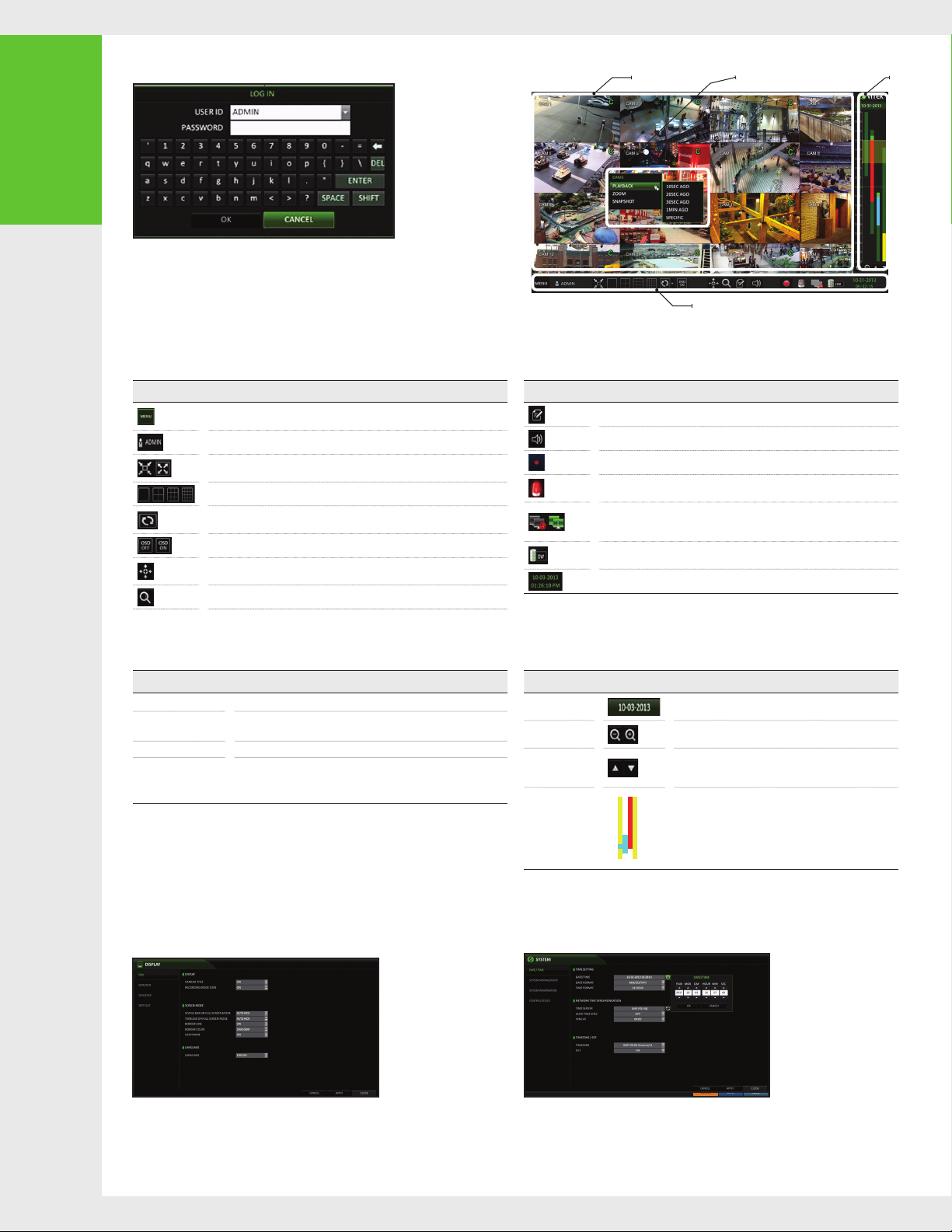
LOG IN
•
When the syste m star ts, the log in scre en appe ars.
1.
Select the user ID and enter t he password.
2.
The def ault use r ID is “AD MIN”; the defaul t passwo rd is “123 4”.
Click < OK>.
3.
•
For safe and sec ure use of the product, c hange t he password af ter purchasing.
LIVE SCREEN
•
Video Window Quick Menu
Status Bar
Time
line
STATUS BAR
•
Item Description
QUICK MENU
•
Item Description
Channel No Displ ay the number of the current cha nnel.
Play Star t playing the video of th e selec ted channel from the speci fied ti me.
Zoom Move to th e Digital Zoom.
Snapshot Capture
BESIDES THE REMOTE CONTROL BUTTON S, YOU CA N ALSO U SE THE B UTTONS ON THE B OTTOM S TATUS BAR TO CONTROL TH E DVR.
Acce ss the DV R's menu; Se arch , Arch iving , System Setup , Record Setup, Log
Out, and Shutdown.
Show the ID of the user who is currently lo gged in .
Edit th e screen layout to show th e stat us bar and timeline at all t imes or only whe n
the mouse curs or hovers on the status b ar/timeline .
Select a spli t mode.
Auto Sequence Mode.
Displ ay or hide t he OSD m enus on t he screen.
PTZ Control. You can control the PT Z opera tions of a PTZ-compliant camera on
the PTZ screen.
Access the Zoom screen.
Capture the current live vide o and save i t in a .jpeg forma t.
•
You can save the captured sna pshot to t he HDD or
expor t it to an external USB memory device.
Item Description
Displ ay the lo g list of recent recorded events.
Select the Audio inp ut channel.
Start emergency recording.
Flashes when an event oc curs . It will not flash if no action to the event has b een set .
Click t o view informat ion abo ut the event tha t occurred.
Check if a network con nect ion is ma de via an ex ternal PC or mo bile device.
Click t his to vi ew the details of the con curre nt users and to check the network
connection status.
Shows the disk sp ace inf ormat ion. I f you have se t the dis k overwrite mod e, it will
be displayed "O W" (Over Write) fro m the st art po int of th e overwriting.
Displ ay the cu rrent t ime and date.
TIMELINE
•
Item Description
Timeline Date
Zoom in /out th e
timeline
Navigation
through Timeline
Timeline Bar
•
Double-click th e timeline to move to the Playb ack mod e. Dra g and dro p it to
make bac kup or event searc h for the sp eci ed are a.
Displ ay the date of the c urrent timeline.
Click t his to se lect a desire d date of t he timeline .
Expand or col lapse t he time line.
Move to th e previo us or nex t point of time in t he time line.
You can also use the mouse whe el to navigate t hrough the
timeline.
Represent the recorded data. The color of each bar indicates:
Green : C onti nuous Recording
~
Red : Ala rm Recording
~
Blue : Mo tion Re cording
~
Yellow: Panic Recording
~
LANGUAGE SETTING
•
1. Press [ SETUP] on the remote cont rol, or selec t <MENU > - <SYSTE M SETUP> from
the st atus ba r.
2. From < SYSTE M SETU P> - < DISPLAY>, sele ct <OSD >.
3. Select a preferred language.
4. Click <APPLY>.
DATE/TIME SETTING
•
1. Press [ SETUP] on the remote cont rol, or selec t <MENU > - < SYSTE M SETUP>
from th e stat us bar.
2. From < SYSTE M SETU P> - < SYSTEM>, select < DATE/ TIME >.
3. Specify th e display format of the cu rrent t ime and d ate.
•
As the exi sting data in the same time and da te will be d elet ed if dup licates
are foun d, back up the existing data for la ter use.
4. Click <APPLY>.
Page 3

3
Recording
4
Search
AUTOMATIC RECORDING SETTING
•
1. Press [ MEN U] on the remote cont rol,
and use the direction buttons to select
<R ECOR D SETU P> an d press [ ENTER] .
Alter natively, you c an sele ct < MEN U> - < RE CORD
SETU P> from the st atus bar.
2. Set < RECORD SE TUP MO DE > to <AUTO
CONFIGURATION>.
3. Select "Automatic Record Configuration Mode".
TIME SEARCH
•
From the < SEARCH > menu, select < TIME S EAR CH >.
1.
Specify th e searc h date and time from the c alendar in
2.
the lef t corner of the s creen .
You can ide ntif y the type of the recor ding data by the c olor
3.
in the ba r.
•
ALWAYS HIGH V IDEO Q UALIT Y :
Recording will proceed in the best quality
regardless of the event at all times.
As this option will always make recording in the
best qualit y, the re cording period is the s hortest
compa red to th e other recor d modes .
•
MOTION RECORD : Recording w ill proceed on ly if a
motion is detected.
•
Yellow Gre en (PR E RECORDING) : Th e pre-recor ding
is performed on the re cordi ng data after you set
the < PRE RECOR DING TIME > from < OPERATIO N
MODE>.
•
Green (Continuous) : The continuous recording is
performed on the recording data.
•
ALAR M RECORD : Recordin g will proceed o nly
if an alarm event occurs.
•
MOTION/AL ARM RE CORD : Recording will
proce ed only if a moti on is detected or an alarm
event oc curs .
•
INTENSIVE M OTION R ECOR D : Reco rding will
be per formed in a low qua lity. H owever, th e
quality will switch t o high if motion event is
detected.
•
INTENSIVE A LAR M RECO RD : Rec ording will
be per formed in a low qua lity. H owever, th e
quality will switch t o high if an alarm event
occurs.
•
INTENSIVE MOTION/ALARM RECORD :
Recording will be performed in a low quality.
However, the quality wil l switc h to high if an
alarm event occ urs or motion is d etec ted.
4. Click <APPLY>.
•
Red (Alarm) : T he alarm event recording is
performed on the recording data.
•
Blue ( Motion) : The m otion event rec ordin g is
performed on the recording data.
•
Yellow (P anic ) : The panic manual reco rding is
performed on the recording data.
Click t o move to a desired s tart t ime in the time
4.
bar, or use t he but tons at t he bot tom of the
status bar to make search.
Select an ite m to play and clic k <P LAY>.
5.
move to a desired time, or s imply double -cli ck a desi red
time in t he time b ar to play the video data on that t ime.
•
For det ails on thumbna il search and event
search, ref er to the u ser manual.
Click t o
5
Network
Setting
NETWORK CONNECTION SETTING
•
Connect the DVR to th e router.
1.
Connect th e [WAN /UPLINK)] por t of the ro uter direct ly to
2.
the fixed IP LAN c able , or con nect i t to the ADSL mod em.
3.
When do ne, co nfigure the port for wardin g for the R TSP
and Web Service por ts by cli cking Port Fo rward ing.
4.
Click < PORT FOR WARDING > for each. You will see
the confirmation me ssage . Clic k <AP PLY> and ex it the
menu.
5.
The net work settings of the DVR are complete.
Note :
Some ro uter mo dels may not supp ort UP NP.
If you see a failur e messa ge aft er clicking < PORT FORWARDIN G>,
refer to the user manual o f the rou ter and c onfig ure the p ort
forwarding settings manually.
TO CONFIGURE THE NETWORK SETTINGS
1.
From the m ain men u of the DV R, move t o <SYS TEM
SETU P> - < NETWORK > - <IP SET UP> .
2.
Use DHC P to get an IP addre ss from t he rout er, or
manually enter an IP address that falls within the
private IP range provided by the router.
•
IP ADD RES S : 192.168 .0.123 (e nter th e network
IP address.)
When the network configuration is
5.
compl ete, procee d with the DDN S sett ings.
From the m ain menu of the DVR, move to < SYS TEM
SETU P> - < NETWORK > - <DDNS>.
Rename the DVR . (The default name of
6.
the DVR i s the MAC a ddress of the DVR. )
Enter a desire d DVR nam e (com binat ion of charac ters
and numbers).
•
GATEWAY : 192.168.0 .1 (ente r the gateway
address.)
•
SUBNET MAS K : 255 .255.2 55. 0 (type the subnet
mask.)
•
1ST, 2ND DN S SERV ER : 168 .126.63 .1 (ente r the
address of a DNS server. )
When do ne, cl ick < DDN S REGISTR ATION TE ST>
7.
and < DDNS CONNECTIO N TES T> in this orde r.
If you receive a su ccess message. Check th e DVR
address and click < APPLY> at t he bot tom.
Check the DVR address and the We b serv ice port
8.
in the ne twork s etti ngs to make sure th at any
Internet-connec ted PC can ac cess the DVR .
If you type "mydv r" for the DVR nam e from the
9.
DDN item, th e address of the We b viewer is
"http: //mydvr.dvrlink.net: 8080".
Page 4

NETWORK CONNECTION
VGA
AUX
DC 12V
VIDEO IN
RS485
NTSC
3
1
7
5
11
9
15
13
4
2
8
6
12
10
16
14
AUDIO
IN
AUDIO
OUT
1/2
3/4
HD MONITOR
VGA
ETHERNET
IN 1
IN 2
GND
IN 3
IN 4
NO
COM
NC
D+
D-
ALARM IN RELAY
PAL
NTSC
AUDIO
IN
AUDIO
OUT
1/2
3/4
2
4
DVR Viewer
DVR Viewer
•
ACCESSING WITH THE BROWSER
•
5
Network
Setting
1
3
5
2
4
6
11
13
7
9
10
8
VIDEO IN
15
12
14
16
AUX
ETHERNET
Broadband router
4WANRESETPWR 3 2 1
or hub
Local PC Local PC
HD MONITOR
AUDIO
ALARM IN RELAYRS485
IN
VGA
1/2
AUDIO
3/4
OUT
D-
D+
NC
NO
IN 1
IN 2
IN 3
IN 4
GND
COM
DC 12V
PAL
NTSC
1. Open the browser and ent er the IP address of the DV R, or e nter th e URL address
in the address bar.
ex) If using the DDNS :
http://00115f123456.dvrlink.net:8080
If using an IP addr ess:
http ://19 2.168 .0 .2 10 : 80 80
For more information about the router and network settings, refer to the user
manual of the respec tive product .
6
Access to the
mobile viewer
When the login d ialog appear s, ent er the us er name
2.
and password.
The def ault ID a nd password
- User name : ADMIN
- Passwo rd : 1234
NOTE : The Username a nd Password are c ase sen sitive.
HOW TO DOWNLOAD AND ACCESS THE IOS-SPECIFIC VIEWER
•
From your iPhone,
1.
access App store
HOW TO DOWNLOAD AND ACCESS THE ANDROID-SPECIFIC VIEWER
•
Click t he upper warning bar to in stall the Ac tiveX
3.
before enabling the add-in function.
When the security wa rning window appears , clic k
4.
<Install>.
Type "Spir e DVR
2.
Viewe r" in the S earc h
bar
When the ActiveX is ins tall ed comp letel y, you will
5.
see the live screen.
For more inform ation a bout using the Web viewer, refer to t he user
manual.
After Installation, select
3.
"Spir e DVR View er" again to
launch t he app
From your Androd
1.
phone , open the Play
Store
Type "Spir e DVR
2.
Viewe r" in the S earc h
bar
After Installation, select
3.
"Spir e DVR View er" icon to
launch t he app
 Loading...