

Page 1

ENVI Series 2.0 MegaPixel 20x
Network PTZ Camera with PoE
VITEK
VT-PTZ220N
• 1/2.8” 2.0 MegaPixel Sony® Exmor™ Progressive Scan CMOS Sensor
• Up to 30fps live view @ 1920 x 1080p
• High speed PTZ operation from 0.1°/sec to 420°/sec.
• XDNR Noise Reduction (Utilizes both 2DNR & 3DNR)
• 16:9 Video format
• True Day/Night with ICR & DSS
• H.264/MJPEG Dual Streaming
• Full duplex 2 way audio, Alarm IN/OUT
• Minimal Latency w/Max 16 User Connections
• Onvif Compliance
• MicroSD Card Slot supporting up to 64GB cards for Onboard EDGE Recording &
Playback
• 12VDC & PoE Plus (Power over Ethernet)
• 3 Year Warranty
Specifications & installation procedure subject to change without notice.
Visit www.vitekcctv.com for the most current information available.
Page 2

ENVI Series: VT-PTZ220N
Table of Contents
1. Box Contents............................................................................................................................ 6
2. Included Accessories ................................................................................................................ 6
3. Available Accessories ................................................................................................................ 6
3.1. Optional Mounts & Housings ......................................................................................... 6
4. VT-PTZ220N Installation ........................................................................................................... 7
4.1. Surface mount Installation ............................................................................................ 7
4.2. Connections ................................................................................................................. 8
4.3. Removable Storage ...................................................................................................... 9
4.4. Attaching PTZ Camera to Base .................................................................................... 10
5. Camera Software Installation .................................................................................................. 11
6. VT-PTZ220N Features ............................................................................................................. 14
7. IP Installer: Introduction ......................................................................................................... 15
8. Installing and Uninstalling ....................................................................................................... 15
8.1. Installing IP Installer .................................................................................................. 15
8.2. Uninstalling IP Installer ............................................................................................... 18
9. Using IP Installer .................................................................................................................... 21
9.1. Starting the Program .................................................................................................. 21
9.2. Search Product ........................................................................................................... 22
9.3. Manual Network Setup ............................................................................................... 23
9.4. Automatic Network Setup ........................................................................................... 25
9.5. Using DHCP Server ..................................................................................................... 28
9.6. Using PPPoE .............................................................................................................. 28
9.7. Updating Firmware ..................................................................................................... 30
9.8. Filter Configuration ..................................................................................................... 32
9.9. Live View ................................................................................................................... 33
10. ENVI Admin Menu ................................................................................................................ 35
10.1. Entering Admin Menu ................................................................................................. 35
10.2. Admin Menu Structure ................................................................................................ 36
11. Quick Configuration .............................................................................................................. 36
11.1. Step 1: Changing Server Name .................................................................................... 36
11.2. Step 2: Time Setup ..................................................................................................... 36
11.3. Step 3: Network Setup ................................................................................................ 36
11.4. Step 4: IPCCTVDNS.COM ............................................................................................ 37
11.5. Step 5: Recording Configuration .................................................................................. 37
11.6. Finish......................................................................................................................... 37
12. System Configuration Menu .................................................................................................. 37
12.1. Server Name Setup..................................................................................................... 37
1
Page 3

ENVI Series: VT-PTZ220N
12.2. Date & Time............................................................................................................... 38
12.3. Admin Password ......................................................................................................... 39
12.4. Access Control ............................................................................................................ 39
12.5. User Registration ........................................................................................................ 39
12.5.1. Add ................................................................................................................. 39
12.5.2. Edit ................................................................................................................. 41
12.5.3. Delete ............................................................................................................. 41
13. Network Configuration .......................................................................................................... 41
13.1. Static IP Configuration ................................................................................................ 42
13.2. DHCP Client Configuration ........................................................................................... 42
13.3. PPPoE Configuration ................................................................................................... 43
13.4. Network Ports ............................................................................................................ 43
13.5. Bandwidth Control Configuration ................................................................................. 44
13.6. View Network Status................................................................................................... 45
13.7. Network Status Notify ................................................................................................. 45
13.8. IP-CCTV DNS Setup .................................................................................................... 46
13.9. Port Forwarding & UPnP ............................................................................................. 47
13.10. RTP/RTSP Setup ......................................................................................................... 48
14. Device Configuration ............................................................................................................ 50
14.1. Privacy Zone .............................................................................................................. 50
14.2. PTZ ........................................................................................................................... 52
14.2.1. PTZ Preset ....................................................................................................... 52
14.2.2. PTZ Scan ......................................................................................................... 53
14.2.3. PTZ Pattern ..................................................................................................... 54
14.2.4. PTZ Tour ......................................................................................................... 55
14.3. Camera & Motion ....................................................................................................... 56
14.3.1. Camera Configuration....................................................................................... 58
14.4. DI (Sensor Input) / DO (Alarm Output) ........................................................................ 62
15. Advanced Configuration ........................................................................................................ 63
15.1. Advanced Services ...................................................................................................... 64
15.1.1. E-mail Service Configuration ............................................................................. 65
15.1.2. FTP (Buffered) Ser vice Configuration ................................................................. 68
15.1.3. FTP (Periodic) Service Configuration .................................................................. 70
16. Recording Configur ation for Cameras with microSD card ........................................................ 72
16.1. MicroSD Configuration ................................................................................................ 72
16.2. Recording Configuration with microSD card .................................................................. 75
17. Utilities ................................................................................................................................ 77
17.1. System Log ................................................................................................................ 78
17.2. Save Configuration ..................................................................................................... 78
2
Page 4

ENVI Series: VT-PTZ220N
17.3. Reboot ....................................................................................................................... 79
17.4. Factory Default ........................................................................................................... 79
17.5. System Update ........................................................................................................... 80
18. ENVI Series Viewer............................................................................................................... 83
18.1. Introduction ............................................................................................................... 83
18.2. Key Features .............................................................................................................. 83
18.3. System Requirement for PC......................................................................................... 83
19. Installing and Uninstalling ..................................................................................................... 84
19.1. Installing ENVI Series Viewer ...................................................................................... 84
19.1.1. Installing on Web Browser ................................................................................ 84
19.1.2. Manual Installation ........................................................................................... 86
19.2. Uninstalling ENVI Series Viewer ................................................................................... 87
19.2.1. Uninstalling with Program Menu ........................................................................ 87
19.2.2. Uninstalling on Control Panel ............................................................................ 88
20. Starting ENVI Series Viewer .................................................................................................. 89
20.1. Control Bar ................................................................................................................ 90
20.2. Channel Control Bar .................................................................................................... 91
20.3. OSD Channels Buttons ................................................................................................ 91
20.3.1. Saving as Image File ........................................................................................ 91
20.3.2. Saving as Video File ......................................................................................... 92
20.3.3. Manual Recording ............................................................................................ 92
20.3.4. Instant Playback .............................................................................................. 93
20.4. Extended Features ...................................................................................................... 94
20.4.1. Pausing Live Video ........................................................................................... 94
20.4.2. FPS Control ..................................................................................................... 94
20.4.3. Flip Control ...................................................................................................... 95
21. EN-V-R: Introduction ............................................................................................................ 96
22. Requirements for Installation ................................................................................................ 97
22.1. EN-V-R Versions ......................................................................................................... 97
22.2. System Requirement for PC......................................................................................... 97
23. Installing EN-V-R .................................................................................................................. 98
24. Uninstalling EN-V-R ............................................................................................................ 100
24.1. Closing Active EN-V-R ............................................................................................... 100
24.2. Executing Uninstaller ................................................................................................ 101
25. Components of EN-V-R Program ......................................................................................... 102
25.1. EN-V-R Configurator ................................................................................................. 102
25.2. EN-V-R Service ......................................................................................................... 102
25.3. EN-V-R Controller ..................................................................................................... 102
25.4. EN-V-R System Tray Menu ........................................................................................ 103
26. Starting EN-V-R Configurator .............................................................................................. 103
3
Page 5

ENVI Series: VT-PTZ220N
27. Quick Start Guide ............................................................................................................... 105
27.1. EN-V-R Configurator User Interface ........................................................................... 105
27.2. Searching for IP Devices ........................................................................................... 106
27.3. Registering IP Devices .............................................................................................. 107
27.4. Viewing Live Video ................................................................................................... 110
27.5. Recording Video ....................................................................................................... 111
28. ENVI Smart Player .............................................................................................................. 116
28.1. Introduction ............................................................................................................. 116
28.2. Key Features ............................................................................................................ 116
28.3. System Requirement for PC....................................................................................... 116
29. Installing and Uninstalling ................................................................................................... 117
29.1. Installing Smart Player .............................................................................................. 117
29.1.1. Manual Installation ......................................................................................... 117
29.2. Uninstalling Smart Player .......................................................................................... 119
29.2.1. Uninstalling on Prog ram Menu ........................................................................ 119
30. Configuring & Viewing Player .............................................................................................. 129
30.1. Main Window View ................................................................................................... 130
30.2. Connecting to NVR Player ......................................................................................... 131
30.3. Creating a Group ...................................................................................................... 131
31. Searching Video ................................................................................................................. 133
31.1. Searching Video ....................................................................................................... 133
31.2. Daily Search ............................................................................................................. 133
31.2.1. Search Mode .................................................................................................. 134
31.2.2. GO to Time Position ....................................................................................... 134
31.3. Condition Search Mode ............................................................................................. 134
31.3.1. Advanced Search Mode .................................................................................. 135
32. Video Playback C ontrols ...................................................................................................... 136
33. Extra Features ................................................................................................................... 137
33.1. Window Control ........................................................................................................ 137
33.2. Recording Period ...................................................................................................... 137
33.3. Backup .................................................................................................................... 138
33.4. Snapshot ................................................................................................................. 139
33.5. Print ........................................................................................................................ 140
33.6. Ratio Display ............................................................................................................ 140
34. EN-V-R Configuration ......................................................................................................... 142
34.1. System, Network Configuration ................................................................................. 142
34.1.1. Configuring System name ............................................................................... 142
34.1.2. System, Network Configuration - Admin password ........................................... 143
34.1.3. System, Network Configuration - Access Control .............................................. 143
34.1.4. System, Network Configuration - HTTP Port..................................................... 144
4
Page 6

ENVI Series: VT-PTZ220N
34.1.5. System, Network Configuration–IP CCTV-DNS ................................................. 144
35. IP-CCTV DNS Registration .................................................................................................. 145
36. IP-Device Registration ........................................................................................................ 151
36.1. IP-Device Registration (Manual) ................................................................................ 151
36.2. IP-Device Registration (Automatic) ............................................................................ 153
IP-Device Modific ation ................................................................................................. 155
36.3. IP-DeviceDeletion ..................................................................................................... 157
36.4. IP-Device Homepage ................................................................................................ 157
36.5. Camera Management ................................................................................................ 157
36.5.1. Configure Camera Name and Information ........................................................ 158
36.5.2. Camera Resolution, Quality ............................................................................. 159
36.5.3. Configure Camera Recording Condition ........................................................... 160
36.5.4. Alarm, Event Configuration ............................................................................. 163
36.6. User Management .................................................................................................... 164
36.6.1. User Registration ........................................................................................... 165
36.6.2. User Modification ........................................................................................... 165
36.6.3. User Deletion ................................................................................................. 166
36.7. Disk Setup ............................................................................................................... 166
36.7.1. Disk Setup ..................................................................................................... 166
36.7.2. Disk Quota Modification and Deletion .............................................................. 166
36.7.3. Disk Mode Change ......................................................................................... 167
36.8. Utilities .................................................................................................................... 169
36.8.1. Email account Configuration ........................................................................... 169
36.8.2. About Program .............................................................................................. 170
37. Using EN-V-R Controller ...................................................................................................... 171
38. Connecting to EN-V-R ......................................................................................................... 172
38.1. PC with EN-V-R installed ........................................................................................... 172
38.2. PC without EN-V-R.................................................................................................... 173
5
Page 7
1. Box Contents
VT-PTWMT
VT-PTIBMT
VT-PTHSG/DIP
VT-PTFMK
Bubble
VT-PTPPMT
VT-PTPDMT
VT-PTCNMT
VT-PTPLMT
1) VT-PTZ220N 20x IP PTZ Camera
2) Mounting Hardware &Accessories
4) ENVI Series CD
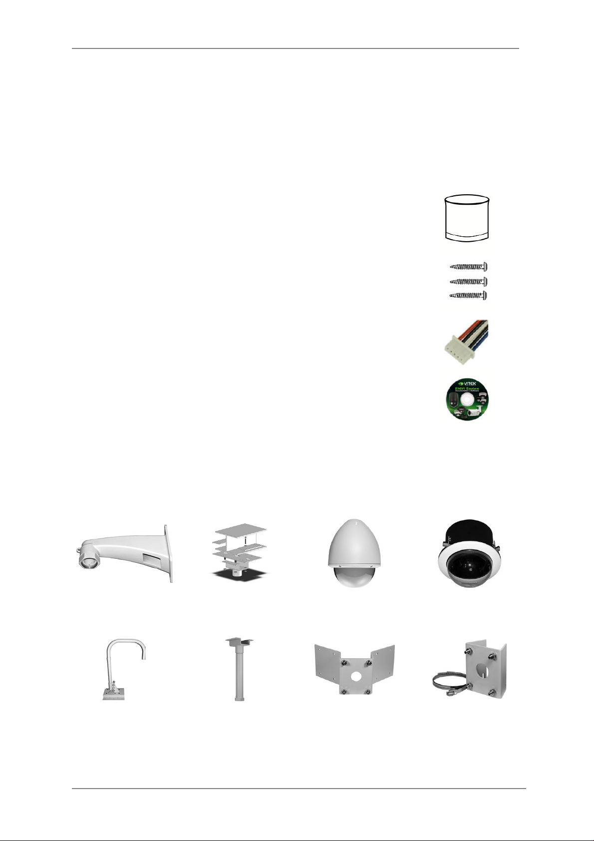
2. Included Acces sories
Surface Mount Housing
Qty: 1
Mounting screws
Qty: 3
Alarm/Multi Cable
Qty: 1
ENVI Series CD
Qty: 1
ENVI Series: VT-PTZ220N
3. Available Accessories
3.1. Optional Mounts & Housings
PTZ Wall Mount
PTZ Parapet Mount
PTZ I-Beam Mount
PTZ Pedestal / Ceiling
Mount
PTZ Housing w/Clear or
Smoked Bubble
PTZ Corner Mount
Adapter
PTZ Flush Mount Kit
w/Clear or Smoked
PTZ Pole Mount Adapter
6
Page 8
ENVI Series: VT-PTZ220N
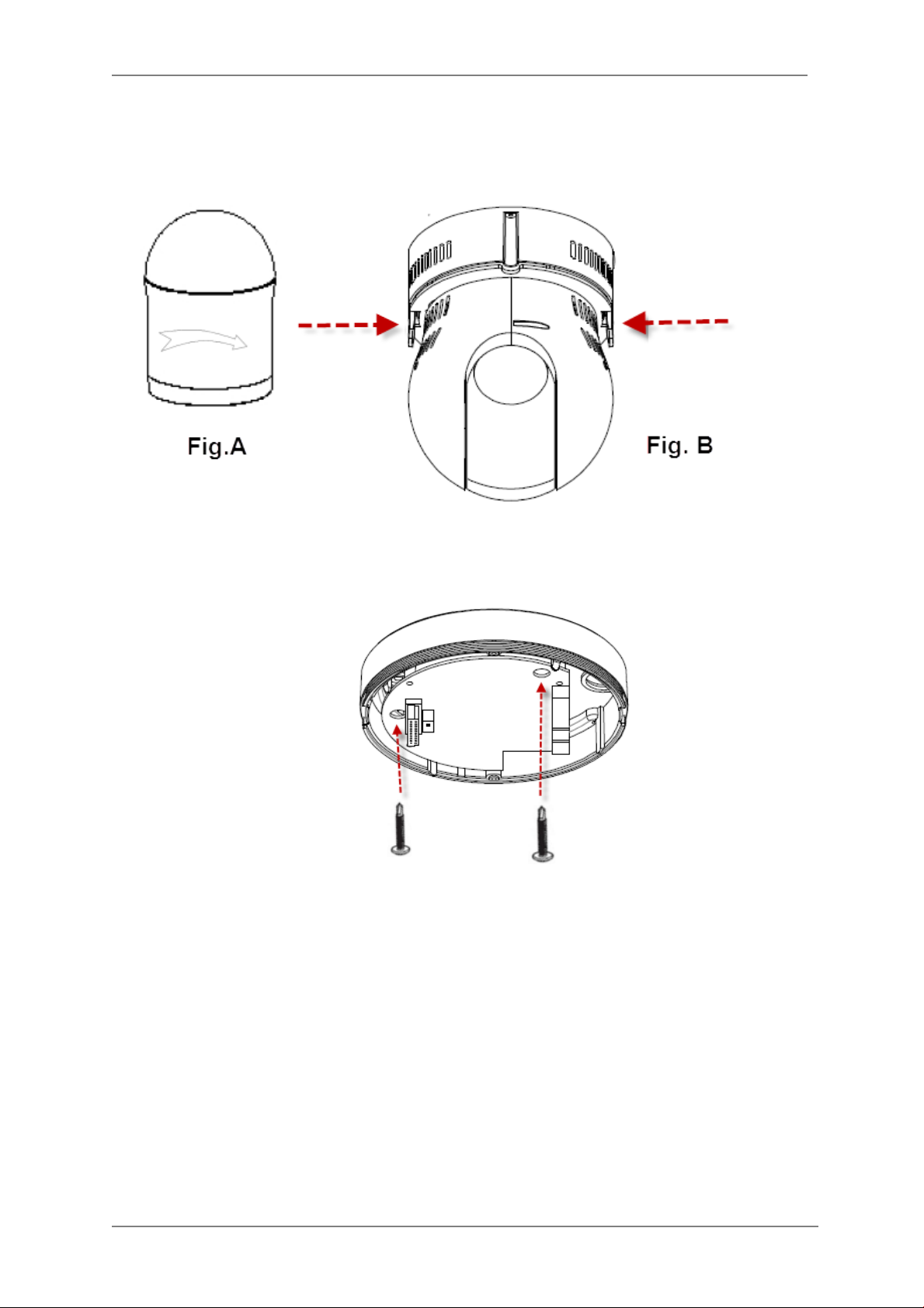
4. VT-PTZ220NInstallation
• Remove by unscrewing the surface mount housing (See Fig. A). Simultaneously push the
right and left hooks from the camera, this will free the camera from the base. (See Fig. B)
4.1. Surface mount Installation
• Attach the PTZ Dome camera base to a sturdy surface with two of the incl uded St4x30
screws.
7
Page 9
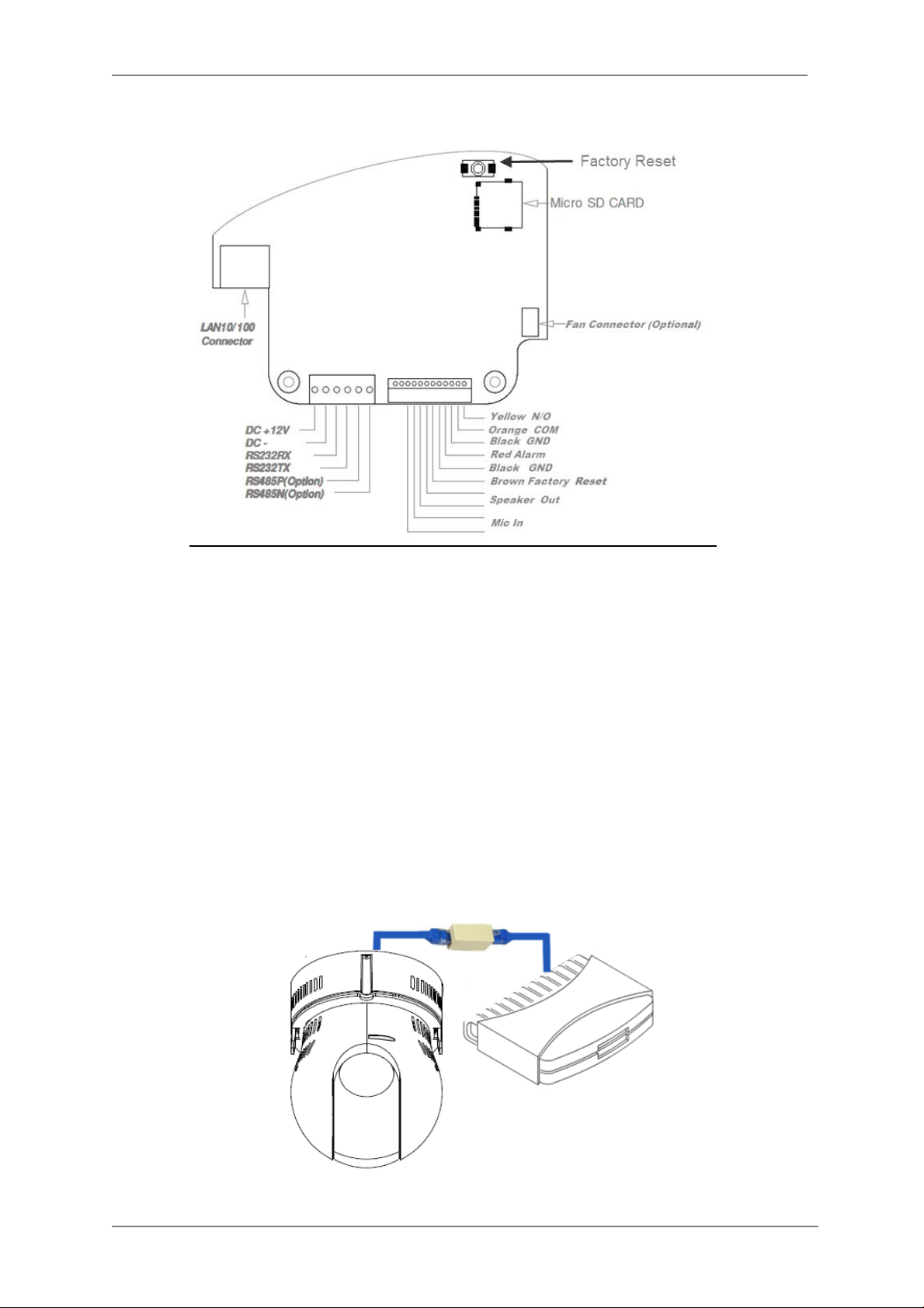
4.2. Connections
ENVI Series: VT-PTZ220N
1. Power
Depending on the type of installations, apply power to the camera by one of the two
options below.
a) Via Ethernet – Use only with POE + switch (100 Meters max distance)
b) 12VDC - Use with 12VDC 2A ** SEE IMPORTANT NOTES BELOW **
Primary and secondary grounds are completely isolated to avoid possible ground-loop
problems.
2. Ethernet Connection
Insert one end of the Ethernet cable into the network jack of your camera, and insert the other
end into the data port (switch, router, etc)
8
Page 10
ENVI Series: VT-PTZ220N
3. Alarm Connections
This camera supports Alarm IN/OUT (x2), Green = alarm IN, Blue = alarm OUT. (For more
information, refer to Section 14.4DI (Sensor Input) / DO (Alarm Output) on page 62)
4. Audio In/Out
This camera supports Audio IN/OUT for more information (Enable Audio under Web-Admin
>Device control >camera and motion configuration. For control and adjust Audio (Viewer
Manual>Audio Control Bar) NOTE: For more information, refer to Section10. ENVI Admin
Menu on page 35.
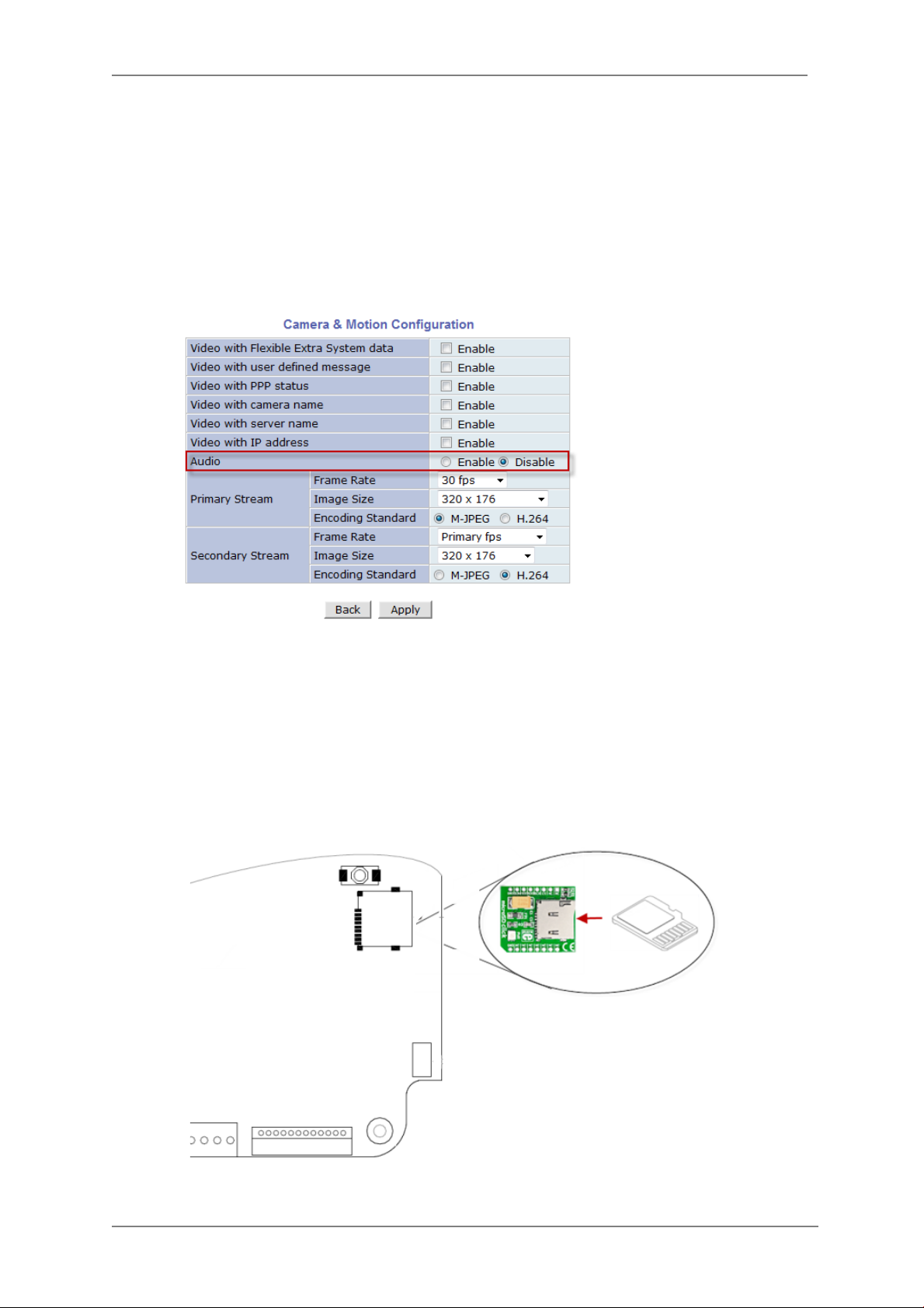
4.3. Removable Storage
For recording directly on the camera you will need to install a MicroSD card, this will allow
you to play video directly from the camera.(Please use only class 10 SD cards).
a) Insert the MicroSD me mory card as shown below (the MicroSD card willneed to be
formatted. (refer to Section 16.1MicroSD Configuration on page 72 for instructions on
Formatting)
9
Page 11
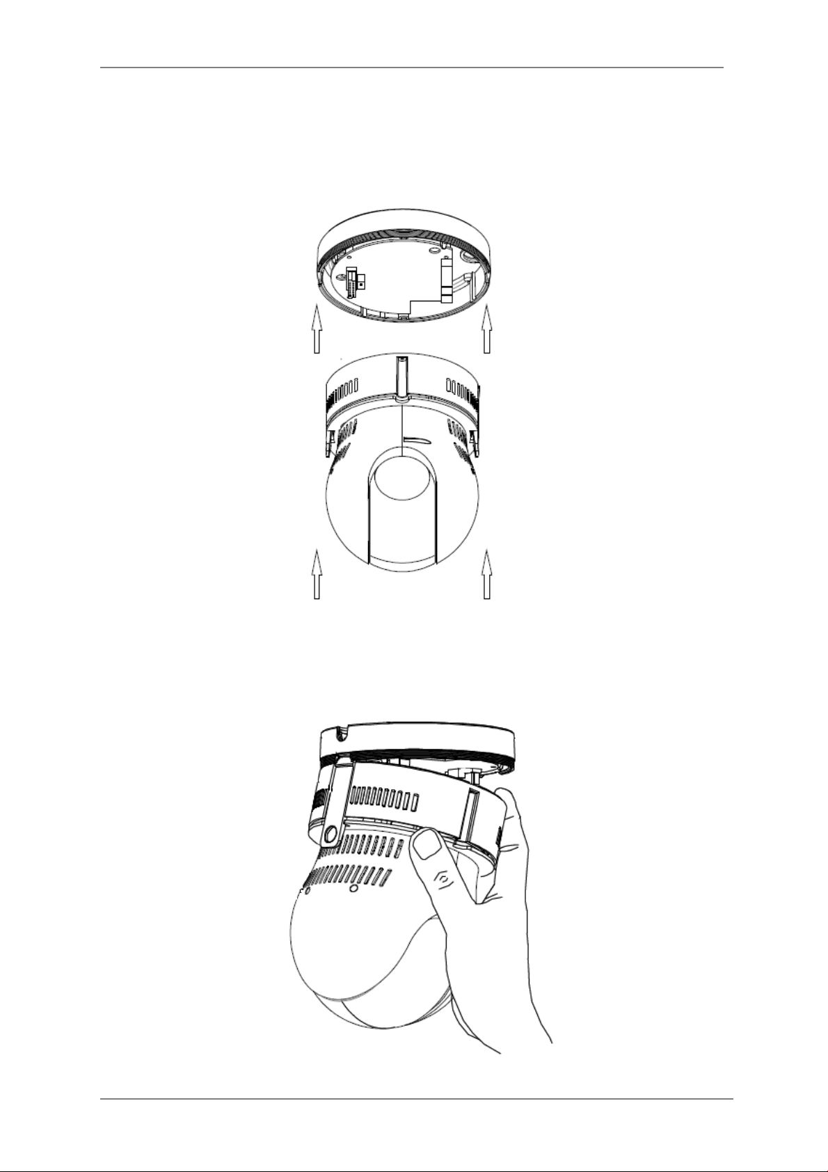
4.4. Attaching PTZ Camera to Base
a) Place the camera on to the Guide and push upwards, you will hear a click from the
camera snapping in to the base.
ENVI Series: VT-PTZ220N
b) Screw back the Surface Mount Housing in to Place.
10
Page 12

ENVI Series: VT-PTZ220N
5. Camera Software Installation
1. Run IP Installer Software from the CD program on a computer that is on the same network
as the IP camera.
2. StartIP Installer, by double clicking the icon “IP Installer”
3. After the program has started, the main window of IP Installer program will appear on the
screen as shown belo w.
4. Search for the installed camera on the network by cl icking the search product icon, the
camera should appear as the image below. The default IP address is 10.20.30.40
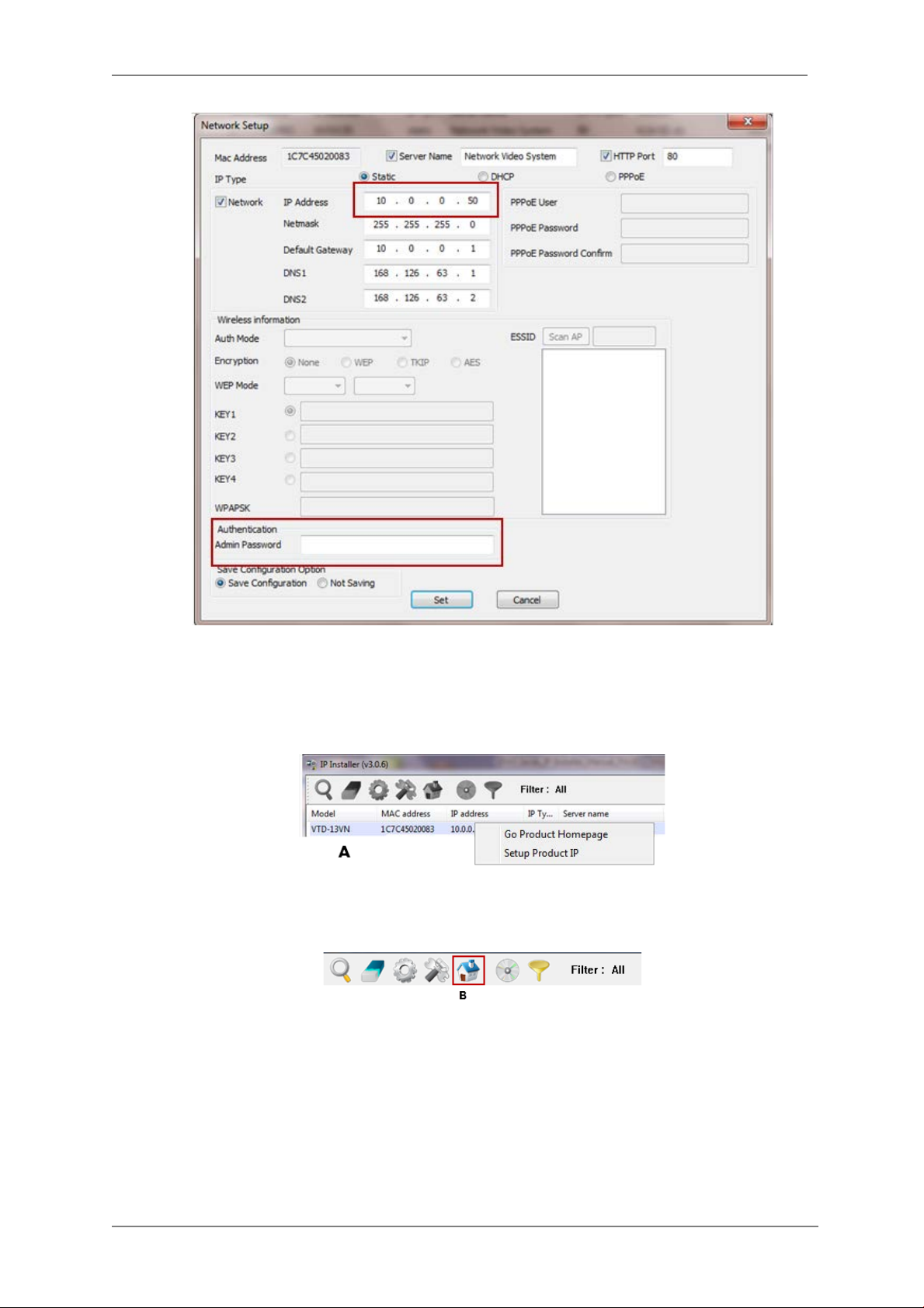
5. To assign an automatic IP address to this camera within the network, click the “Automatic IP
Setup” icon
6. Verify the Automatic IP address provided, enter the default password root and then click Set
as shown below.
11
Page 13
ENVI Series: VT-PTZ220N
7. After the camera was configured by the program automatically, you will be able to get access
by
a) Right click over the camera information, “
b) Click over the icon “
8. From the Home Page, you can “
Connect Product Homepage
Live View”
Go Product Homepage
”
or administrate
“Admin”
”
the camera.
12
Page 14

ENVI Series: VT-PTZ220N
On Live View you will be able to see live video from your camera.
NOTE: For more information, re fe r to Section 10. ENVI Admin Menu on page 35
.
13
Page 15

6. VT-PTZ220N Features
ENVI Series: VT-PTZ220N
2.0 MegaPixel 20x Network PTZ Camera with PoE
Progressive Scan CMOS Sensor
• Up to 30fps live view @ 1920 x 1080p
• High speed PTZ operation from 0.1°/sec to 420°/sec.
• XDNR Noise Reduction (Utilizes both 2DNR & 3DNR)
• 16:9 Video format
• Auto TDN without focus shift by dual fil ter switcher
• True Day/Night w ith ICR & DSS
• H.264/MJPEG Dual Streaming
• Full duplex 2 way audio, Alarm IN/OUT
• Minimal Latency w/Max 16 User Connections
• Onvif Compliance
• SD memory card slot for Local recording
• 12VDC & PoE + (Power over Ethernet) Dual Voltage
• 3 Year Warranty
+1/2.8” 2.0 MegaPixel Sony® Exmor™
14
Page 16
ENVI Series: VT-PTZ220N
7. IP Installer: Introduction
IP Installer is a proprietary utility program for VitekIP products. It enables users of Vitek products
to search their network for any Vitek network camera, video server, or network video recorder no
matter what IP address it has. By using IP Installer, u sers will be able to facilitate network setup
process for Vitek products deployment.
Runs on Microsoft Windows operating system (XP, Vista, 7, 8)
Search for Network Cameras, Video Servers, and Network Video Recorders
Capable of firmware updating
Support automatic and manual IP setup
8. Installing and Uninstalling
** It’s recommended to install this program as an administrator **
8.1. Installing IP Installer
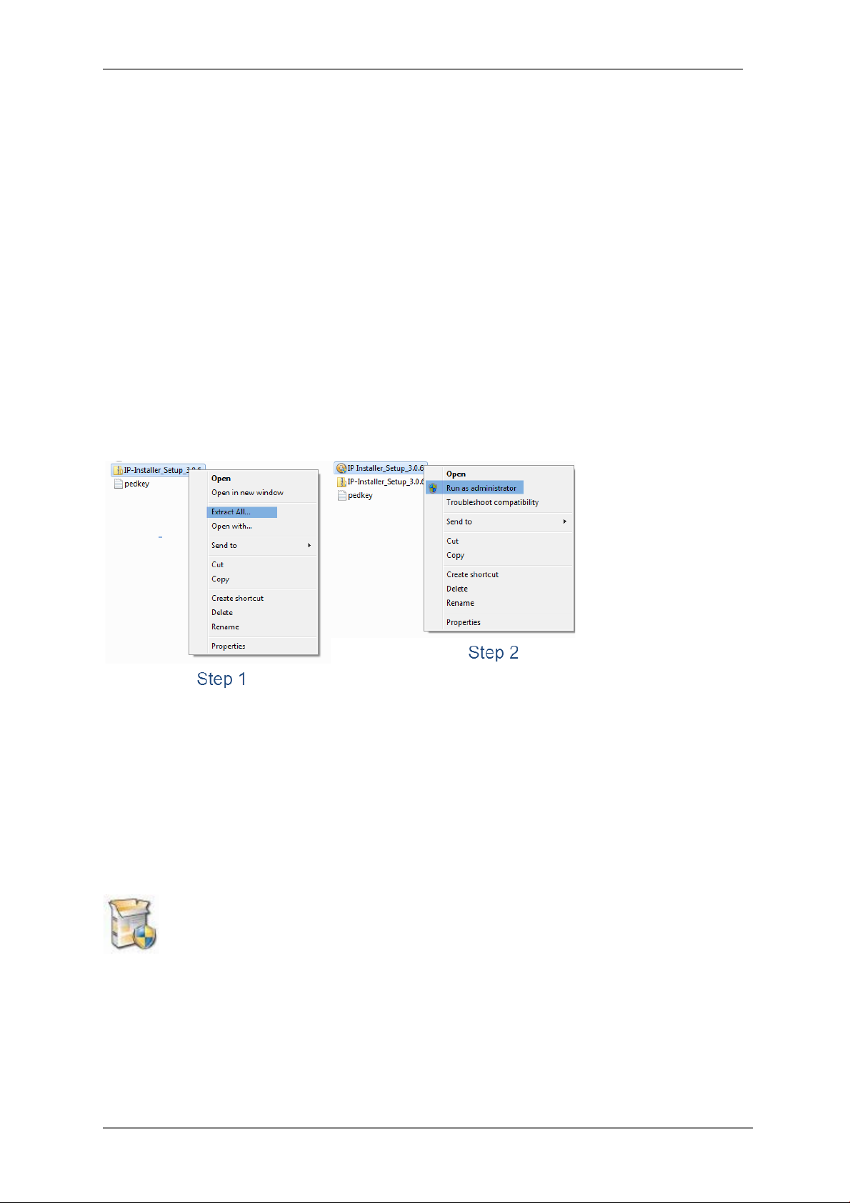
If the program is started from the CD supplied with Vitek products, insert the CD in to CD/DVD tray
and check the installation file. If it is download or copied from the Internet or any other media,
locate the file from the PC’s hard drive. You will see the icon as shown with t he file name IP
Installer_Setup_x.x.x.exe. The actual file name in your case may vary as the version changes.
Double click the icon to star installation.
15
Page 17

You may be prompted to co ntinue running the installation program.
Click Yes button, then the following window will be shown on the screen.
ENVI Series: VT-PTZ220N
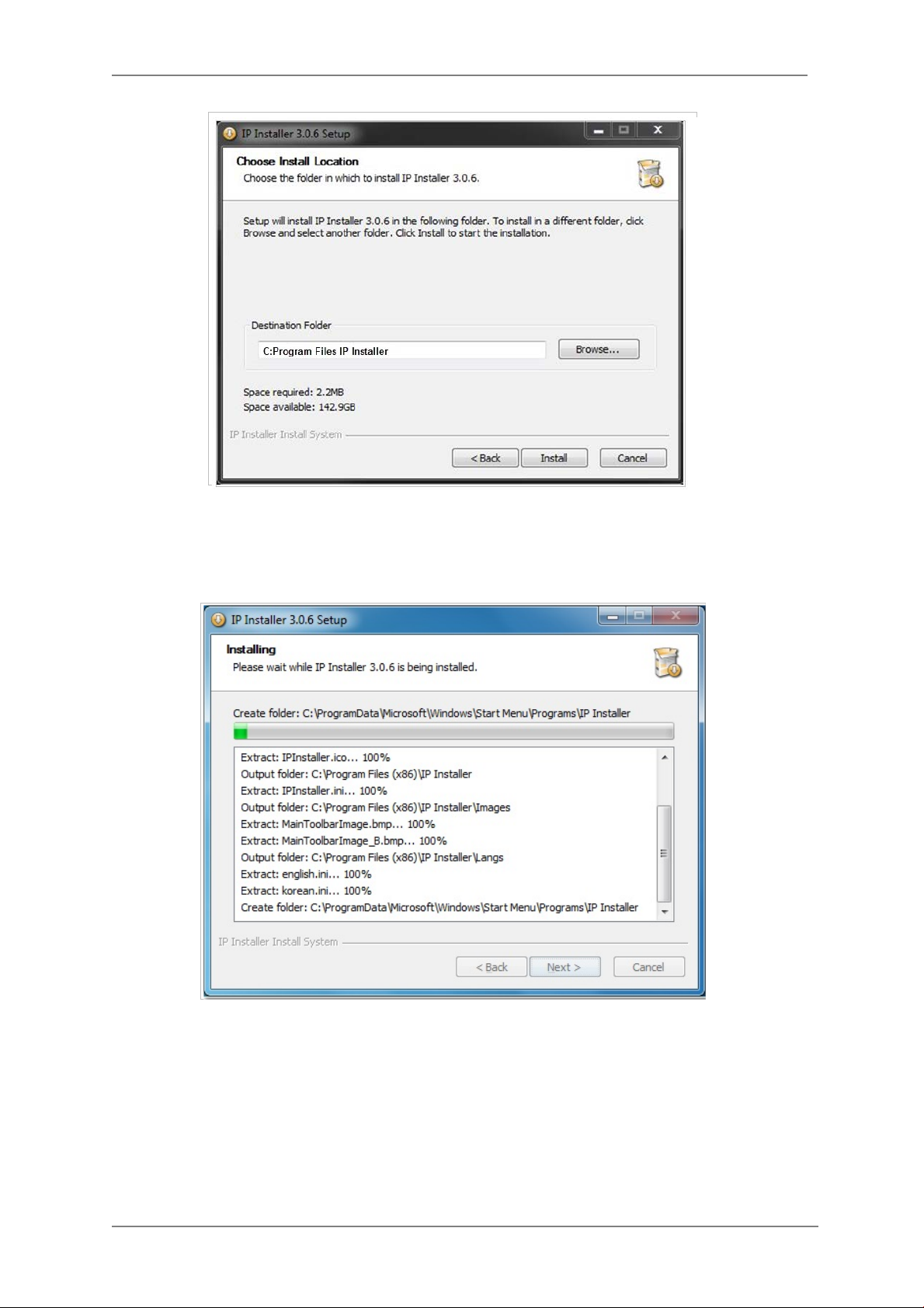
To continue the installation, click Next. The following window will be displayed for location to
install.
16
Page 18
ENVI Series: VT-PTZ220N
The default location for installation is C:\Program Files\IP Installer. It is recommended to install
in this folder, if you want to change it to a different location, click the Browse button to choose
location. Now click the Install button. You will see the progress of theinstall as shown below.
17
Page 19
ENVI Series: VT-PTZ220N
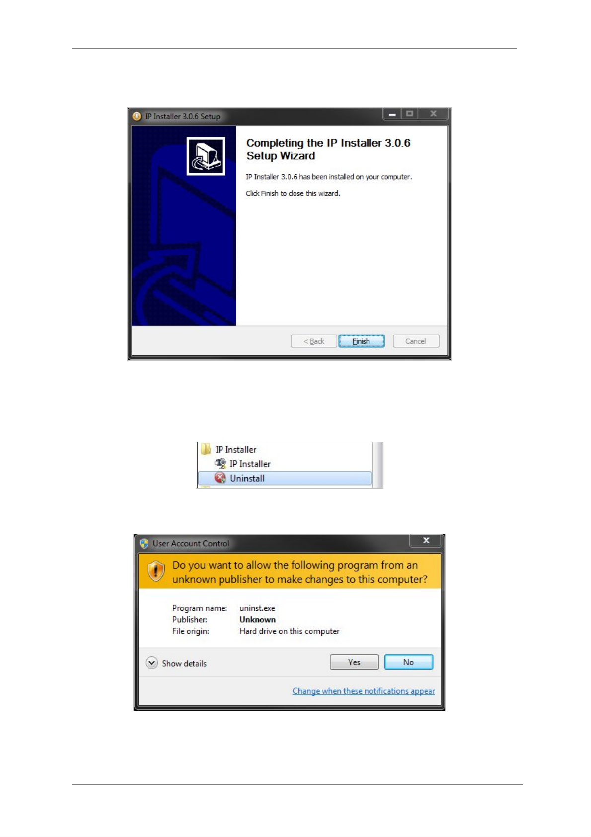
When the files are done copying, the following window w ill be shown. Click the Finish button to
complete the installation.
8.2. Uninstalling IP Installer If you want to remove the IP Installer program from your PC, click Start > All Programs > IP
Installer > Uninstall.
You may be prompt to continue running theuninstall program.
18
Page 20

ENVI Series: VT-PTZ220N
Click onthe Yes button, then the following window will be shown on the screen.
Click on the Next butt on and you will see the following window.
Click on the Uninstall button to start removing the IP Installer program from your computer.
The following window will be displayed.
19
Page 21

ENVI Series: VT-PTZ220N
Click on the Finish button to close the window
20
Page 22

ENVI Series: VT-PTZ220N
9. Using IP Installer
9.1. Starting the Program
Once IP Installer program has been installed on your computer, a shortcut icon
should be created on the desktop of your computer.You can star t IP Installerby
double clicking the icon.
Or you can also start the program by clicking Start > All Programs > IP Installer > IP
Installeras shown below.
After the program has started, the main window of IP Installer program will appear on the
screen as shown belo w. There are no netwo rk devices shown,as it is the first time running the
program and nothing has been registered.
Search Product
Clear Product List Clear the Vitek products list created by searching the network.
Automatic IP Setup Configure the network setting of selected IP device in Automatic mode.
Manual IP Setup Configure the network setting of selected IP device in Manual mode.
Connect Product
Homepage
Update Firmware Update the firmware of the selected IP device.
Filter Configuration Define the range of MAC and IP addresses to search.
Scan the network and shows the list of all the Vitek products that IP
Installer program found.
Connect to the server homepage of the selected IP device.
21
Page 23

ENVI Series: VT-PTZ220N
9.2. Search Product
Make sure that your Vitek products are powered and connected to the network, and then
click the Search Product button. A status window will pop up to show the progress of
the search. Wait until it reaches 100%, or you may press the Cancel button to stop the
search at any given timeand proceed with the results made until that moment.
After searching is completed 100%, the IP Installer program will display the IP devices found.
If you want to clear the list of the IP Devices from the window, click Clear Product List
button from the Main Toolbar .
22
Page 24
ENVI Series: VT-PTZ220N
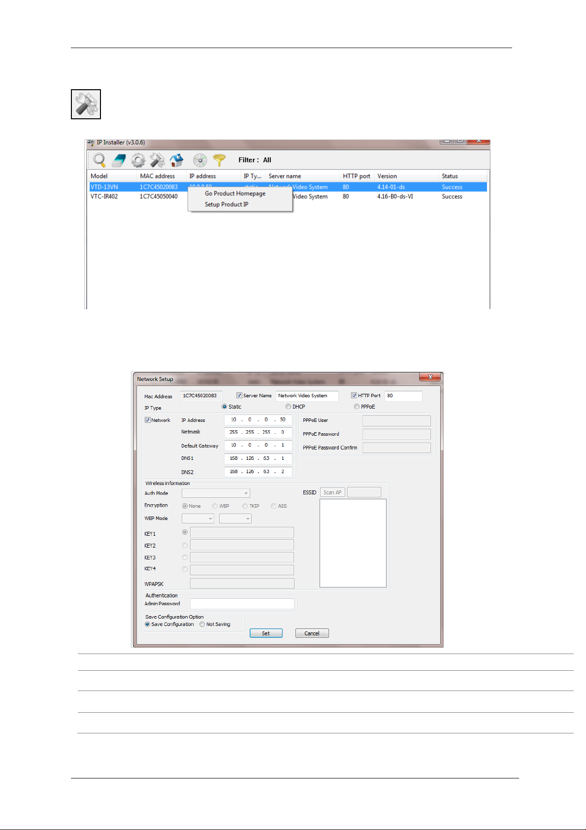
9.3. Manual Network Setup
Configuring the network parameters of the devices in the list can be started either by
highlighting and right clickingmouse button or by clicking Manual IP Setupbutton on the
main Toolbar.
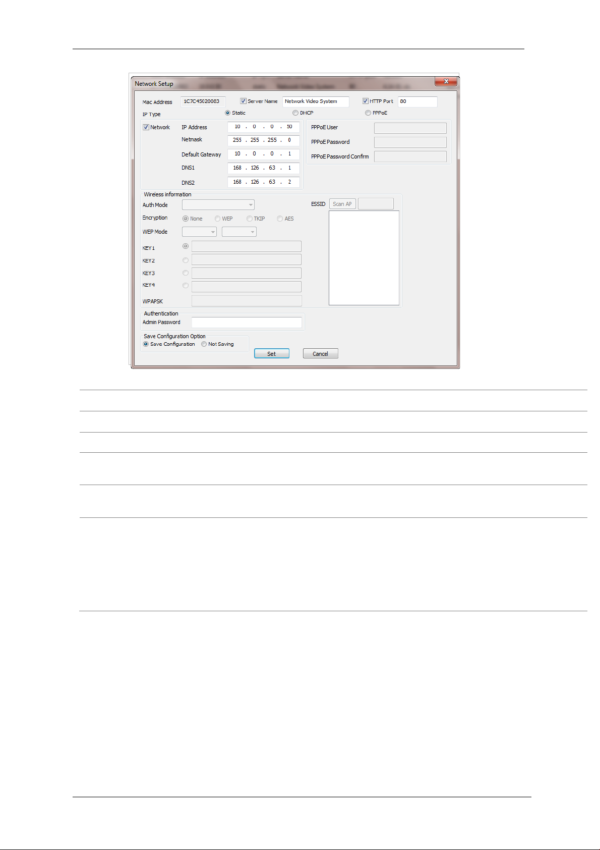
When one IP device is selected, the following screen will appear
MAC Address MAC address of the selected device is shown.
Server Name Input desired name of camera i.e. Lunch Room
HTTP Port Input port number to access IP devices homepage via web. Default port is 80
IP Type Select the type of address (Static / DHCP / PPPoE) Use STATIC for manual IP setup
23
Page 25
ENVI Series: VT-PTZ220N
Network
Authentication
(Admin Password)
Save Configurati on
Option
Click Set button to ap ply the changed values to IP device. If you don’t want it, click Cancel button.
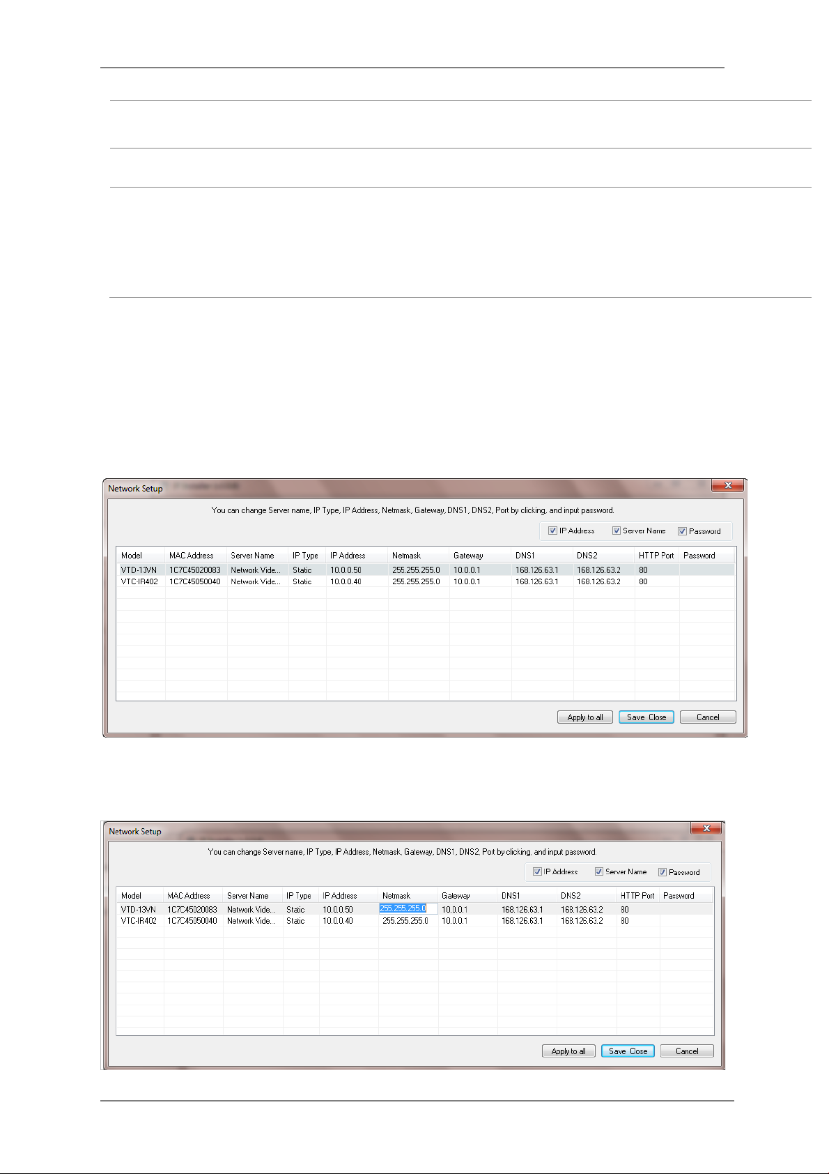
When two or more IP devices are selected
You can select two or more IP devices at the same time by clicking one after another while CTRL
key is pressed. The result is shown as below.
To configure the network parameters of those devices, click the right mouse button or click
Manual IP Setup icon on the main Toolbarwith multiple IP devices selected as shown above.
Then the following window will show up.
General network parameters are required in this part. Please contact your network
administrator for detail.(IP Addr es s , Netmask, Default Gateway, DNS1, DNS2)
Password for the IP device.
(Default password for Vitek products is “root” unless already changed)
Select whether the configured contents is to be saved in the Camera memory or not.
• Save Configuration: Changed values will be saved in the Camera memory of
the device, which means the changes are permanent.
• Not Saving: Cha nged values will not be save d in the Camera memory, which
means if the IP device is turned off the changes are lost and the previous
setting will be applied back.
You can modify the value of each changeable field by clicking it. The following shows an example
of entering a new value to a field.
24
Page 26
ENVI Series: VT-PTZ220N
Static
Model Model Numbers of the IP devices that you selected.
MAC Address MAC address of the selected device is shown.
Server Name Name of the selected IP device.
IP Type
IP address, Netmask,
Gateway, DNS1, DNS2
HTTP Port HTTP port number of the IP device for web access to homepage.
Password Password for the IP device.(Default password for Vitek products is “root”)
If you click Apply to all button after changing just a field of one IP device, the remaining IP
devices will have the same value for that parameter. In this case, each device’s Server name and
IP Address field will have +1 incremented value added to the original value. For example, if the
first IP device has been given the server name of NetCam and Apply to all button is pressed, it
will be automatically changed to NetCam1 and the next IP device will have NetCam2 and so on.
The same applies to the IP address field.
How to assign IP address to the device (Select
Setup)
General network parameters are required in this part. Please contact your
network administrator for detail.
here for Manual IP
For Password field, the entered information doesn’t increment but will use the same data.
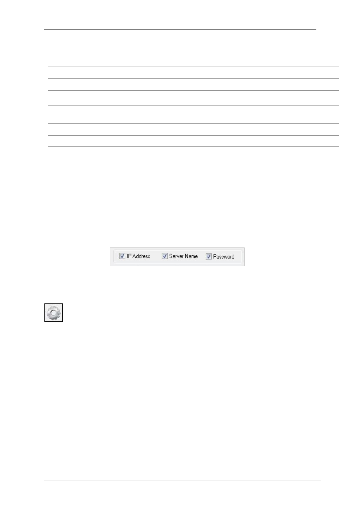
In using Apply to all, you can choose which field is affected. Put check marks only on the field
you want to use this automatic action as below.
Click Save & Close button to save the changed values in the camera memory of all the IP devices
and close the Network setup window.
9.4. Automatic Network Setup
Configuring the network parameters of the devices in the list can be started either by
clicking right mouse button or by clicking Automatic IP Setupbutton on the main
Toolbar. Before starting the setup, you first need to choose t he one to be configured. In
this setup mode, IP Installer program checks your local network and assigns available IP addresses
to the IP devices. You have a choice of using those automatically assigned IP addresses, or you
can just enter other IP addresses as you desire.
25
Page 27
ENVI Series: VT-PTZ220N
Server Name Name of the selected IP device.
HTTP Port HTTP port number of the IP device for web access to homepage.
IP Type How to assign IP address to the device (Select Static here for Manual IP Setup)
Network
Authentication
(Admin Password)
Save Configurati on
Option
Click Set button to apply the changed values to IP device. If you don’t want it, click Cancel button
to restore the previous values.
General network parameters are required in this part. Please contact your network
administrator for detail. (IP Address, Netmask, Default Gateway, DNS1, DNS2)
Password for the IP device. (Default password for Vitek products is “root”)
Select whether the configured contents is to be saved in the Camera memory or not.
• Save Configuration: Changed values will be saved in the Camera memory of
the device, which means the changes are permanent.
• Not Saving: Cha nged values will not be saved in the Camera memory, which
means if the IP device is turned off the changes are lost and the previous
setting will be applied back.
26
Page 28

ENVI Series: VT-PTZ220N
Note: If your network has more than one IP address Zone at the same time, the
confirmation window will be displayed as below. You need to choose the one you
are going to use for your IP devices.
27
Page 29
ENVI Series: VT-PTZ220N
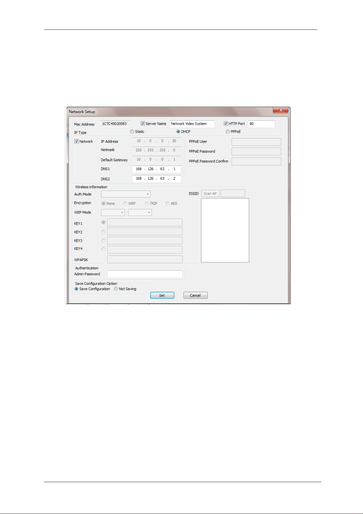
9.5. Using DHCP Server
If your network has a DHCP server running for assigning IP addresses, you may choose to let it
assign IP addresses to the IP devices on the list. To do that, first open the Network Setup window
either by Manual IP Setup or Automatic IP Setup procedure. Choos e DHCP in “IP Type”
selection, then IP Address, Netmask, Default Gateway field in Network setup area on the
window will be disabled to input as shown below.
For setting up other fields on the setup window, refer toSection9.3Manual Network Setup on
page 23. After filling the fields wit h appropriate values, click Set button to apply the changed
values to IP device. If you don’t want it, click Cancel b utton to restore the previous values.
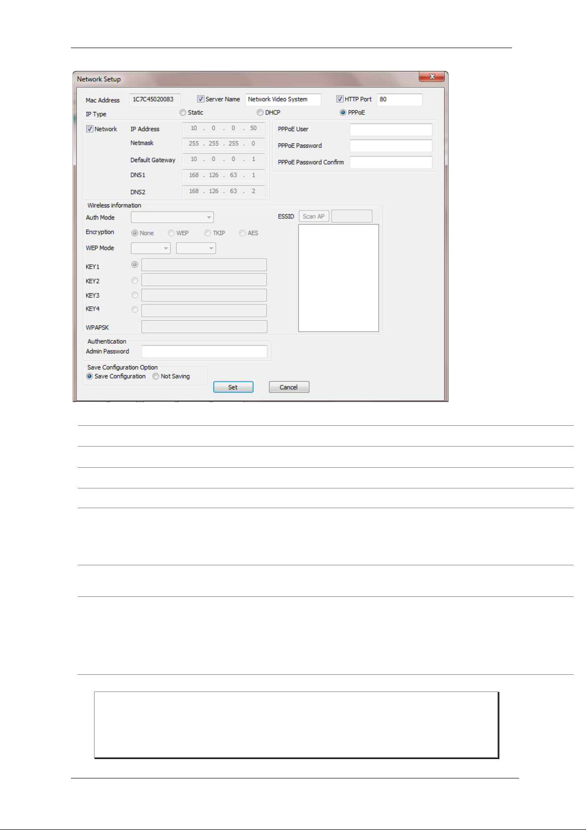
9.6. Using PPPoE
If your network environment is based on PPPoE connection, you’ll need to choose PPPoE on IP
Type selection. Fir st open the Network Setup window either by Manual IP Setup or Automatic
IP Setup procedure. Choose PPPoE in IP Type selection, and then all the fields in Network
setup area on the window will be disabled. The network settings such as IP Address, Netmask,
Default Gateway and DNS are no longer available to enter. You only need to enter the Server
Name, HTTP Port num ber, and login authentication for your PP PoE connection.
28
Page 30
ENVI Series: VT-PTZ220N
9.9
MAC Address MAC address of the selected device is shown.
Server Name Name of the selected IP device.
HTTP Port HTTP port number of the IP device for web access to homepage.
IP Type How to assign IP address to the device (Select PPPoE in this mode)
User Authentication for PPPoE Connection.
• PPPoE User: Enter User ID.
PPPoE
Authentication
(Admin Password)
Save Configurati on
Option
• PPPoE Password: Enter Password for the User ID.
• PPPoE Password Confirm: Enter the same Password again.
Password for the IP device.
(Default password for Vitek products is “root” unless already changed)
Select whether the configured contents is to be saved in the Camera memory or not.
• Save Configuration: Changed values will be saved in the Camera memory of
the device, which means the changes are permanent.
• Not Saving: Cha nged values will not be saved in the Camera memory, which
means if the IP device is turned off the changes are lost and the previous
setting will be applied back.
Note: After setting up the network for the IP devices, make sure the IP devices are
accessible on the network from your computer. It can be done by running Live
View function of the homepage of the IP device’s built-in server. Refer to
Section
29
Live Viewon page 33
for how to do it.
Page 31

ENVI Series: VT-PTZ220N
9.7. Updating Firmware
Once IP devices are searched and shown on the screen as functioning successfully, you can update
the firmware of them in IP Installer program. T o do tha t, first check the firmware version of the
device, which you can find on the IP Installer window.
In the above picture, the firmware version of this product is 4.14-01-ds while the latest
firmware version available is 4.16-B0-ds-VI as you could see at Vitek’s homepage
(
http://www.vitekcctv.com/Downloads.asp). If you decide to update the firmware, first
create a folder on your computer for the update firmware, than download the latest firmware to
that folder.
Then select the IP device to be updated on IP Installer window, then click Update Firmware
button from the toolbar. The following window will be displayed.
You may find the Password field is empty on the window shown above. If so, click the Password
field of the IP device and enter the proper password for the device. You are not allowed to update
the firmware if the correct password is not provided.
After the password is entered, the Star t U pdate button will be enabled now. Click the button to
see the following window for selecting the folder where the file has been saved.
than click
OK.
Highlight the folder
30
Page 32

ENVI Series: VT-PTZ220N
After clicking OK the following window will be displayed.
Note: Do not CLOSE window until completed, to avoid permanent damage to the camera.
You can also select multiple IP devices at the same time, and have them start firmware updating in
a single step. Select the files to update by holding CTRL key and selecting w hich IP devices to
update
Click Start Update button. You will see the update window brought up with multiple IP devices
listed.
The rest of the procedure is the same as in the firmware update case for a single IP device.
31
Page 33

ENVI Series: VT-PTZ220N
9.8. Filter Configurati on
When you need to search only for the IP device having a specific range of MAC or IP
addresses, you can do it by using this feature. To set the search condition, click Filter
Configuration but ton on the Toolbar, then the following window will show up on the
screen.
The first six HEX characters are already filled in with 1C:7C:45, which is the MAC prefix for
Vitekproducts. Put a checkmark inMAC Address or IP Range to set the range f or searching.
You can set the range of IP addresses to scan as shown below. In this example, all the IP devices
having MAC address starting with 1C:7C:45 will be listed on the result window after scanning.
Or you can look for a single IP device having a specific IP address as below.
IP Address range for searching can be entered as follows.
You may even set both MAC Address and IP Range together at the same time.
After setting the searching range as explained above, click OK button. Then IP Installer program
window will show the searching range on the top right portion of the window as shown below.
32
Page 34

ENVI Series: VT-PTZ220N
To start searching with this condition now, click Search Product button on the toolbar.
The program will start searching and show the result after a moment.
9.9. Live View
Once searching and configuration on IP d evices are done, you should make sure that the IP
devices are accessible with the new settings. The best way to do it is by connecting to the
homepage of each IP device’s built-in server, and starting Live View feature.
Select Go Product Homepage when you click the rightmouse button on the IP device to test.
If you select Go Product Homepage, the homepage of that device’s built-in server will
be opened on a new Web browser window as shown below. This is the same result when
you click Connect Product Homepage button from the Main Too lbar.
33
Page 35

ENVI Series: VT-PTZ220N
Click Live View on the top right of the window, then ENVI Series Viewer ActiveX program will be
started. If you have not installed the ENVI Series Viewer program before, it will ask for a
confirmation to install it. Allow it and you will be able to find out whether the configuration by IP
Installer program is properly done.
Note: Refer to
Section 18
ENVI Series Viewer
on page83
for detailed information about
the ENVI Series Viewer ActiveX program.
34
Page 36

ENVI Series: VT-PTZ220N
10. ENVI Admin Menu
After connecting to a VITEKENVI Series camera via web browser, you’ll find the web page as
shown below. The upper rightmost item of the menu is Admin; this is where you can set up most
of the features in the VITEK camera you’re connected to.
10.1. EnteringAdmin Menu
Click Admin then yo u’ll see a login window.In the login window, enter root for both ID and
password as they are the factory defaults. Press Enter key or click OK.
Now the Admin Menu will be displayed as shown below. This will guide you to the top level menu
items, which are Quick, System, Network, Device, Advanced, Recording, and Utilities. Clicking any
of these top level menu items will display submenu ite ms and brief descriptions.
35
Page 37

ENVI Series: VT-PTZ220N
10.2. Admin Menu Structure
The following table shows the hierarchy of the Admin menu structure that we’re going to deal with
in this manual.
11. QuickConfiguration
In Quick Configuration, you will be able to set up many of the essential parts of the configuration
in a simple manner without going into details. Sel ecting Quick Configuration gives you the menu as
seen below. You can perform each setup by clicking the one you would like to configure.
11.1. Step 1:Changing Server Name
Click Server Name on System Configuration menu, then Server Name Setup windows will be
displayed.Refer toSection12.1Server Name Setupon page 37to see how to change the server
name.
11.2. Step 2: Time Setup
Click Date & Time on System Configuration menu, then theLocal Date & Time Configura tion
window will be displayed.Refer toSection12.2Date & Timeon page 38to see how to se t up.
11.3. Step 3: Network Setup
To make a connection to the Internet, it is required to figure out the type of the Internet service
you’re using. Refer toSection13. Network Configuration on page41to see how to set up.
36
Page 38

ENVI Series: VT-PTZ220N
11.4. Step 4: IPCCTVDNS.COM
When VITEK Server is used in a Dynamic IP environment, it is required to utilize IPCCTVDNS
feature. Refer to Section 35. IP-CCTVDNS Registration on page 145to see how to set up.
11.5. Step 5: Recording Configuration
Vitek cameras with MicroSD card can be configured for recording options in this section.Refer to
Section 16.1MicroSD Configuration on page 72to see how to set up.
11.6. Finish
After clicking Finish all changes will be saved automat ically to the camera/server
12. System Configuration Menu
When you click on System Configuration item on Admin Menu, the following sub menu will be
displayed.
12.1. Server Name Setup
Click Step 1 on Quick Configuration or Server Name under System Configuration then the
following will be displayed and you will find out the system information such as model number of
the VITEK camera, server name (camera name), MAC address (serial number), firmware version,
and Web image version.
37
Page 39

ENVI Series: VT-PTZ220N
As an administrator, you can change the name of the camera/ server, but other values are not
allowed to be changed. To change the camera/ servername, enter a new name in the Server
Name field. You may use up to 21 alphanumeric or up to 10 Unicode characters. Tab or any other
special characters are not allowed. Click Apply button to save the setting and it will take effect
immediately.
12.2. Date & Time Click Step 2 on Quick Configuration . Or Date & Time under System ConfigurationFill t he
Date and Time fields with your local time and date information. If you're in a different time zone,
put a checkmark on Change Time Zone, then select the correct region from the dropdown list to
make the time zone change, you need to click Apply button and reboot the system.
If you want to retrieve the exact current time from a NTP server on the network, click Get NTP
Server Time button. Clicking Refresh button will display the date and time retrieved from
thecamera. Then click Apply button to save it.
Note: In order to retrieve Time and Date information from a NTP server, you need to put
NTP server add ress in advance of setting up, such as pool.ntp.org.
38
Page 40

ENVI Series: VT-PTZ220N
12.3. Admin Password
To change the pass word for the administrator, click Admin Password in System Configuration
menu.
Default ID for adm in account is fixed as “root” and is not allowed to change. I n Old Password
field, enter the curr ent password. In both New Password and Confirm Password fields, enter
the same new password. The password must be between 4 and 23 alphanumericcharacters.Click
Apply button to put it into effect.
Because you have replaced the password with a new one, the existing network connection made
with old password to VITEK camera is lost now. You will have to reconnect to the VITEK camera
using new password.
12.4. Access Control
Click Access Control on System Configuration menu. The following windows will be displayed.
From the Access Permission window, select either one you would like to use. Click Apply button
to save the change.
• Full Access: Any user can acce ss the camera/server and use all the features without limits.
• Limited Access: Only registered users can access the camera/server and have limited
privileges.
12.5. User Registration
You can add, modify, or dele te users for your VITEKcamera/server here. Once registered as
Limited Access setting, the user can access the VITEKcamera/server with some limited privileges.
12.5.1. Add
To add a user, click User Registration on System Configuration menu.When Add is selected,
you can add users and define their passwords, names, and access permission levels respectively.
39
Page 41

ENVI Series: VT-PTZ220N
Enter aUser ID between 4 and 23 alphanumeric characters. In bothPassword and Confirm
Password fields, enter the identical password respecti vely. The password must be between 4 and
23 alphanumeric characters. In Name filed, enter the user’s name up to 23 alphanumeric
characters.
Now select one of the four items from System Resource Access Permission, which de fi nes the
permission level for registered users to the VITEKcamera.
• All Channels Access: User can use all the features except for Configuration in Admin Page.
• General Access (only live viewing access): User can only useLive View feature.
• No Access: User is not permittedany of the features.
• Selective Access: User is allowed to use only the selected features. With this item selected,
you can now configure the details under this menu for the user.
VITEKcamerasmay have multiple VS Modules registered in it. Whe n you click on any of
theEnablecheckboxes, other fields in that row are now enabled to select.
40
Page 42

ENVI Series: VT-PTZ220N
• VS Module ID: VS Module is a network device that has been registered in theVITEKcamera
• Camera No.: Among the cameras of the VS Module select one to set up. (between all,1or2)
• Alarm Control: Determine if Alarm control is to be allowed.
• Audio Control: Determine if Audio Control is to be allowed.
After finishing the registration process, click Applybutton to add the user.
12.5.2. Edit
To edit a user account, select Edit. In this part, you can mo dify the existing user’s name,
password, and access permission. User ID is not allowed to change. Once selecting a user ID to
edit, the procedure is the same as in Add section.
To see existing users, click Select UserId, and select a user to be edited from the dropdown box.
Then you can change the password, name, or access permission, and clickApply button to save
the setting. Setup o f Access Permission can be done the same way as in theAdd section.
12.5.3. Delete
To delete an existing user, select Delete.
From the list of the users, select a user to delete. Click Delete button to confirm the d eletion.
13. Network Configuration
Configuring the netw ork is dependent on how an IP address is assigned in Ethernet-based
environment, which is static IP, dynamic IP (DHCP), or PPPoE.
41
Page 43

ENVI Series: VT-PTZ220N
13.1. Static IP Configuration
Select Network Configuration under Network configuration
For static IP, select Static IP and input IP address, NetMask, Gateway, DNS1, DNS2 and click
apply to save settings. After apply, program will ask to close web browser for updates, which will
take 20~30 seconds. If Back button is clicked all values will be disca r d ed. If Refresh button is
clicked, the program will load previous values.
13.2. DHCP ClientConfiguration To use DHCP a DHCP server must exist in the network environment.Select DHCP Clientfrom
NetworkConfiguration, click Apply. And all information needed will be filled in automatically
42
Page 44

ENVI Series: VT-PTZ220N
13.3. PPPoE Configuration
PPPoE is used to connect VITEK products to a PPPoE modem provided by the ISP. Since PPPoE
needs verification, ID and a password are necessary to access the networ k. T ype in PPPoE user ID
and password
13.4. Network Ports
In this configuration, you set up the HTTP port for VITEKcameras to communicate with the Client
PC. HTTP Port is the network port that is used when a Client PC connects to the VITEKcamera Web
page. It can be assigned between 80 and 65535.The default value is 80.
Note: If the HTTP port number is changed to a differentvalue than default (80), make
sure the new HTTP port number goes together with the VITEK camerasIP address.
For example, when a VITEK cameras IP address is 192.168.1.100and the HTTP
portis 8080, you will have to enter http://192.168.1.100:8080 to con nec t to the
camera.
43
Page 45

ENVI Series: VT-PTZ220N
13.5. Bandwidth Control Co nf igur ation
Bandwidth control is for limiting maximum network traffic. If it is enabled with Bandwidth limits,
maximum data size transferred from VITEKcameras won’t exceed bandwidth limits set by users. If
transferred data is exceeded, part of the data will be randomly lost.
If multiple users try to access a VITEKcamera when bandwidth control is enab led, users connected
to the VITEKcamera will share network bandwidth limit.
Note: This bandwidth control feature w orks well in M-JPEG video transmission. But, for
H.264, dropping data packets may cause low quality of video, so it is
recommended to utilize CBR and frame rate control instead of bandwidth control
for H.264 video.Refer to Section 14.3
info on CBR and Frame rate.
Note: Network Bandwidth control is managed by theVITEKcamera and it drops any data
packets if required, thus you may experience slow connection when this feature
is enabled.
Camera & Motion
on page 56 for more
44
Page 46

ENVI Series: VT-PTZ220N
13.6. View Network Status
This menu shows network status of VITEKcameras.
13.7. Network Status Notify
This feature helps to send updated network status information to registered email address if any
changes happen. This function will work under DHCP or PPPoE.
If Network Status Notify is set to Enable, VITEKcameras network status will be emailed to a
specific person in case of the following events:
• When it is set to Dynamic IP in theNetwork Configuration menu, and the VITEKcamera
has been given a new dynamic IP address and connects to the network.
Or,
• When it is set to PPP Client on WAN-Modem menu, and the VITEKcamera has been
connected to the network with ISP or PPP server.
To configure, click Network Status Notify on Network Configurati on m en u. The fol low i ng
window will be shown.
45
Page 47

ENVI Series: VT-PTZ220N
First, select Enable to use the feature. Then e nter the address of the SMTP server which is
needed for email service. If your SMTP server requires a user ID and a password for authentication,
you will have to Enable Authentication Loginand enter the user ID and Password.
In Sender field, enter your email address or other meaningful words that will show the message
was sent from the VITEKcamera as a notification. Now enter the email addresses of the recipients
in the Recipient fields, up to 3 addresses. In the User-Defin ed Mess a g e box, you may enter a
message to explain why the message was sent. After finishing the setup, click Apply to save
settings.
Mail Notification
SMTP Server SMTP Server address for email service
Authentication Login
User ID User ID for SMTP server
Password Password for SMTP server
Sender Email address of Sender or Name
1st / 2nd / 3rd Recipient Email Addresses of the Recipients (up to 3 addresses)
User Defined Message Message to be included in the Notification email
Enable: Send email
Disable: Do not send email
Enable: user ID and password arerequired for SMTP server
Disable: user ID and password are not required
13.8. IP-CCTV DNS Setup
Note: Refer to Section 35. IP-CCTVDNS Registrationon page145for further details on
configuration.
IP- CCTV DNS service provides a static & public domain name to help user’s access VITEKcameras
even though their IP address has changed or they are used in a local network. For proper function
of IP-CCTV DNS service, product s need to be accessible through the internet.
46
Page 48

ENVI Series: VT-PTZ220N
.
13.9. Port Forwarding & UPnP
UPnP(Universal Plug and Play)is a kind of network protocol t o help users to find and configure
network products in the same local network area . Port forwarding is to assign a certain network
port to a network product so users can access it from outside of the Local Area Network. Generally,
port forwarding can be configured from the network router.
UPnP port forwarding is made up with finding an available network port, assigning it to a
VITEKcamera and reporting overall network configurati on of a VITEKcamera to IP-CCTV DNS
server. Users have to register products into IPCCTVDNS server and IP-CCTV DNS service should be
enabled.
There are 3 options in UPnP Port Forwarding.
• Manual: User Assigned Portissued when users can acce ss network router(hub) and
manually assign available network ports to VITEKcameras. In this case, users have to type
already-assigned network ports under User Assigned port.
• UPnP: User Assigned Port is used when users want VITEKcameras to configure port
forwarding of network hub with user-assigned network port. If it fails, try to cha nge userassigned port
• UPnP: Auto Selected Portis used to let VITEKcameras deal with all network configurations
automatically.
Please note that the network router needs to support UPnP Port Forwarding. There is a limit forthe
maximum number of UPnP devices. If it is properly configured, results will be displayed under
UPnP status.
47
Page 49

ENVI Series: VT-PTZ220N
13.10. RTP/RTSP Setup Factory default is Enable to be used with other manufactures VMS software’s
RTSP (Real-Time Streaming Protocol) is a protocol to transfer video and audio streams over the
network. Any application supporting Standard RTSP can be used for VITEKcameras. Quick Time
Player or VLC program can be used withthis; it may not be supported in the environment within a
firewall. There are two types of usage; one for Unicast address condition and the other for
Multicast address condition.
For Unicast Address:
Use“rtsp://network video server ip address/cam0_0”. If there are multiple channels, use
cam0_x, x (0~3) with each number applied. If there are multiple modules, use camx_0 x (0 ~ 3)
with each module number applied.
For Multicast Address:
Use “rtsp://network video server ip address/mcam0_0”. If there aremultiple channels, use
mcam0_x, x (0~3) with each channel number applied. If there are multiple modules, use mcamx_0
x (0 ~ 3) with each module number applied.
48
Page 50

ENVI Series: VT-PTZ220N
In normal case, use default port number 554 to connect to RTSP service.
Service
RTSP Port
RTP Start Port
Multicast
Address
Multicast Port Port number for viewing the video with a multicast address
Enable: Start RTSP service
Disable: Stop RTSP service
If not using port 554, enter the port number you want to use.
e.g.) port number 445==>rtsp:// network video server ip
address:445/cam0_0
The starting number of the port for video transfer. Each time video
transfer connection is made, the port number also increases.
Address for multicast video transfer.
The multicast address 0.0.0.0 is for stopping multicast.
49
Page 51

ENVI Series: VT-PTZ220N
14. Device Configuratio n
14.1. Privacy Zone
Users can set a privacy zone if a certain part of the screen needs to be unmonitored.
To set the region, click Privacy Zone from Device Config ur ation category.
To Add a Privacy zone click Newbutton, aGreen-colored box will appear, click on the Green box
and it will turn Red, at this point you can resize it by clicking and holding any corner and drag to
desired size. To relocate box click and hold anywhere inside the box and drag to desired location.
Click Apply when done
50
Page 52

ENVI Series: VT-PTZ220N
Users can add up to 8 Privacy Zones per screen by repeating above steps. If you add more than 8,
an error message will display on the screen.
To delete a privacy zone, click the zone and click Delete button followed by Apply button.
51
Page 53

ENVI Series: VT-PTZ220N
14.2. PTZ
This section will allow you to assign Presets, Scans, Patterns and Tours.
14.2.1. PTZ Preset
• Speed:Not used for Presets, fixed at 420° per sec.
• PTZ Move Mode: Not used for presets, fixed on Continuous
• Index: PTZ Preset Number. (1~32 preset)
• Mode: On: Preset available, Off: Preset unavailable
• Preset Name: PTZ Preset name; editing by user.(Up to 16 characters)
• Camera Settings: Camera se ttings for current Preset only
Execution
1. Speed not used
2. Move PTZ camera with the Navigation buttons, zoom in-out to desired view for preset.
3. Select the Index(preset) number between 1~32.
4. Select the Mode to On.
5. Edit the title of the Preset Name.
6. Edit the camera settings.
52
Page 54

ENVI Series: VT-PTZ220N
7. Click the “Set” button to set camera function.
8. Click the “Apply” button to store preset.
14.2.2. PTZ Scan
The function of Scan is to move the camera automatically between two defined points.
• Speed: not used under PTZ Scan.
• PTZ Move Mode: Not used under P TZ Scan
• Index: Sequence Number of PTZ S c an.(Up to 16 scans)
• Start: Scan area setup.
• End: Scan area setup.
• Mode: OFF: Scan dis able.
On(Normal): Move from start point to end point in panning only.
On(Diagonal): Move from start point to end point including tilt and zoom simulta neously
On a diagonal line
• Speed: Speed of scan to Move from start point to end point.(1~8)
• Direction: Scan direction: CCW (Counter Clock Wise) CW(Clock Wise)
• Swap Position: Swaps the start point for the end point.
• Dwelling: Dwell time at the start and end point, 03– 99 seconds.
Execution
1.Navigation buttons
2. Select the Index number.
3. Position the camera to the Start location using the navigation buttons, then press “Start” button.
53
Page 55

ENVI Series: VT-PTZ220N
4. Position the camera to the Stop location using the navigation buttons then press “End” button.
5. Select the scan Mode: On(Normal) / On(Diagonal)
6. Select the scan Speed 1~8 8 being fastest
7. Select the scan Direction.
8. Select the Swap Position.
9. Select the Dwelling time.
10. Click the “Apply” button to store scan.
11. Select the Scan numberin theindex.
12. Select the mode “On”.
13. Click the “ Run” button to test
14.2.3. PTZ Pattern
A pattern records a user-defined series of pan, tilt, zoom and focus movements.
Up to 8 patterns can be programmed for the PTZ dome camera.
• Speed: set the speed of the camera movment
• PTZ Move Mode: not used under PTZ Pattern
• Index: Sequence Number of PTZ Pattern.(Up to 8 patterns)
• Start: Record ing start for pattern. (Recording time: maximum 480 seconds between all Patterns)
• End: Recording end for pattern.
• Mode: On: pattern Stored, Off: pattern Deleted
Execution
1. Select a pattern number. Index1~8
2. Select the mode “ON”
3. Click “Start” button, pattern recording starts. Use the Navigation buttons to move the PTZ in the
Pattern you want
4. Click “End” button when done and then it will be saved.
The total recording time between all Patterns is 480 seconds
Click the “Apply” button to store pattern
5.
6. Select thepattern number in index previously selected in step 1.
7. Select the mode “On”.
8. Click the “Run” button to test
54
Page 56

ENVI Series: VT-PTZ220N
14.2.4. PTZ Tour
With the PTZ Tour you can combine different camera functions previously configured, such as
Patterns,Presets, Scans and Tours.
8 programmable tours are available each tour can consist of up to 8 functions (Preset, Pattern,
Scan or other Tours ). When using a Tour within a Tour any Tour that is in the 2
nd
Tour will be
ignored.
Example: Tour 2 consists of “Preset 02, Preset 03, Tour 01, Scan 08” any Tour within Tour 01 will
be ignored
• Speed: Not used under PTZ Tour
• PTZ Move Mode: Notused under PTZ Tour
• Index: Tour number
• Mode: On: pattern Store, Off: pattern Delete
• Function Type: None, Preset, Pattern, Scan or Tour
• Function ID: the Index number of the Function Type
• Speed: the speed between Functions
• Dwelling: the time between Functions
Execution
1. Select a Tour n umber in index.
2. Select the mode “On”.
3. Select a function type (pattern, preset scan or Tour).
4. Select the predefined function ID. (The number of Function type example: Preset 01 or Scan
08)
5. Select the speed and the dwelling time.
6. Click the “Apply” button to store tour
7. Select thepreviously selected Tour number in index in step 1.
8. Select the mode “On”.
9. Click the “Run” button to test
55
Page 57

ENVI Series: VT-PTZ220N
14.3. Camera & Motion
This menu is used to set up the selection of video format, data added to video data, encoding
speed, audio control, image res ol ut i on, video quality, motion detection, etc.
Click Camera & Motion on Device Co nf iguration menu. The configuration menu will be
displayed, and it may be different between VITEKcameras.
• M-JPEG: This format requires much higher network bandwidth than H.264 compression. But
because of its higher quality of still image, it is ade q uate for detailed reviewing of stored
video.
• H.264: In this format, each frame data is related to other nearby frames. For this reason, it
provides much higher compression ratio than M-JPEG and is adequate for video transfer.
However, if network conditions are limited dropped frames in video data is possible, the video
56
Page 58

ENVI Series: VT-PTZ220N
quality can be relatively low. With VITEKCameras, you can set the number of P-frames in the
video which is independent still images between I-frames.
Note: For Dual Stream products, most of the parameters are dependent on primary
stream value.
You can configure the video data format and other information to be contained in it.
• Video with Flexible Extra System data: If Enabled, video data will contain UA RT sensor
(
data from COM port..
• Video with user defined message: If Enabled, video data will contain the user-defined
data. (Reserved Field).
• Video with PPP status: If Enabled, video data will contain PPP connection status..
not available on this model)
• Video with camera name: If Enabled, video data will contain the camera name..
not available on this model)
• Video with server name: If Enabled, video data will contain the server name that you
(
defined..
• Video with IP address: If Enabled, video dat a will contain the IP address of the video
server..
• Audio: (not available on all models) Select if Audio function is to be used (applies to Primary
Stream only). VITEK Cameras provides 2-way audio streaming by combining microphone
input with video data. Users can listen to the streamed audio through a PC and speakers.
57
Feature not available on this model)
(
Feature not available on this model)
Feature not available on this model)
(
Feature not available on this model)
(
Feature
(
Feature
Page 59

ENVI Series: VT-PTZ220N
• Frame Rate: For Primary Stream, this is the number of frames compressed in every second.
You can control the network traffic with this parameter. For Secondary Stream, it can be set
to a manner of 1/2, 1/4, 1/8... of the primary stream.
• Image Size: Select t he resolution of each channel’s video
• Encoding Standard: Select the compression method of each video, either M-JPEG or H.264
format. It is not allowed to set both channels to M-JPEG.
Below is the table of images sizes. To save the setting, click Apply button
Video Format SXGA D1 CIF QCIF
NTSC - 704 x 480 352 x 240 160 x 112
PAL - 704 x 576 352 x 288 160 x 144
VGA - 640 x 480 320 x 240 160 x 112
1.3M Pixel 1280 x 1024 640 x 480 320 x 240 160 x 112
2.0M Pixel 1920 x 1080 640 x 480 320 x 240 160 x 112
14.3.1. Camera Configuration
On the lower part of Camera & Motion Configuration menu, select a channel to configure.
In the example shown below, Primary Stream is set to H.264 for compression format.Enter
detailed parameters of the camera selected here.
Primary Stream of (H.264)
• Camera Name: Enter the name of the channel up to 21 alphanumeric or up to 10 Unicode
characters.
58
Page 60

ENVI Series: VT-PTZ220N
Rate Control Mode
Rate Control Mode
Rate Control Mode:VBR (Variable Bit Rate)
Video frames are encoded with selected
image quality and GOP. Encoded frames have
different data size from each other.
H.264
Rate)
Video frames are encoded with selected
image quality and GOP.Encoded frames have
the same data size as other frames. Due to
the constant bit rate, ithas better stable
transmission performance.
M-JPEG -
Image Quality Setup
In Image Quality level setup, select “Low Compression” for higher image quality, but it requires
higher network bandwidth. Selecting the “Lowest” requires lower network bandwidth, but gives
decreased image quality.
: CBR (Constant Bit
Image Quality:one of 6 quality levels
(Low Compression / Highest /High
Normal / Low / Lowest)
GOP Structure: Distance between IFrames. That is filled with P-frames.
Bit Rate Control: Total number of Bits
encoded per second. The higher Bit
Rate, the better image quality. Can be
set between 32kbps and 2Mbps.
GOP: Distance between I-Frames. That
is filled with P-frames.
Image Quality: one of 6 quality levels
(Low Compression / Highest / High
Normal / Low / Lowest)
After configuration is finished, click Apply button to save the setting. If you click Default button,
the entire configuration will be reset to the original values.
Camera Contr o l (Select Models)
Select Camera Control on the bottom of Camera & Motion Configuration menu.
59
Page 61

ENVI Series: VT-PTZ220N
• Focus Mode:Manual, Auto or One-Push (Default is Auto)
• Focus Sensitivity: Low, Normal (Default is Normal)
• Focus Limit: used with Manual Focus ( Default is 32cm)
• White Balance Mode: Auto, indoor, outdoor, ATW, Manual. In manual mode you can
adjust the “Red” and “Blue” Gain (Default is Auto)
• Exposure Mode: Auto, Manual, Iris, Shutter, Bright. In Manual mode the Iris, Gain and
Shutter can be adjusted. In Iris mode the Iris can be adjusted. In Shutter mode the Shutter
can be adjusted. In Bright mode the Brig htness can be adjusted (Default is Auto)
60
Page 62

ENVI Series: VT-PTZ220N
• Exposure Slow Shutter: Turn On/Off Slow Shutter
• Exposure Day & Night: Auto, B/W, Color. In “Auto” Day time will be Color and Night time
will be Black & White. In “B/W” camera will stay in B lack & White. In “Color” camera stays
Color
• Exposure Bright Offset: -7~+7. Brightness of the image -7 being darker and +7 being
brighter. (Default is 0)
• Exposure Back Light: On/Off. Turn Backlight control on or off. (Default is Off)
• Exposure WD R Mode: On/OFF. Turn WDR On or Off (Default is Off)
• Sharpness:Sharpness of the Image 0~15 the higher the setting the more noise will
appear (Default is 9)
• Maximum Digital Zoom: x2, x4, Max. the Digital Zoom level (Default is Off)
• View Angle Flip: Not used (Use Installation Environment)
• View Angle Tilt Limit: -5~+10. The maximum horizontal angle to view (default is -5)
• System Auto Calibration: On/Off. Turn on to Auto Calibrate Camera (Default is Off)
• Installation Environment: Normal, Desktop. In Desktop mode image is rotated 180°
(Default is Normal)
• Preset Freeze: On/Off.
• PTZ Speed: Slow, Medium, fast. The speed of the PTZ movement (Default is Fast)
After all the settings areconfigured, click Apply button to save it.
Motion Detection
• Motion Detection:(this is only available in Primary Stream) If enabled, Motion Detection
feature is activated and user can configure the areas where motion detecti on function will
work. Click Check All button for whole scene to be active (grid will turn Green) then click on
any box inside scene to take out that area from Motion Detection (b ox will turn Red) then
clickApply to save
• Motion Sensitivity: Set the sensitivity of motion defined in Motion Detection Area. Select
between -100 and 100. 100 is the most sensit ive.
61
Page 63

ENVI Series: VT-PTZ220N
DI/DO Setup
DI/DO Control
After all the settingsare done, click Apply button to save it. If Default button is clicked, all the
fields return back to original value.
14.4. DI (Sensor Input) / DO (Alarm Output)
Select DI/DO from Device Configu ration menu to name and co nfigure Sensor Input and Alarm
Output. After configuring, select DI Status/DO Control on Device Config uration menu to
manually control DO (Alarm Output) and check status of DI (Sensor Input).
DI/DO functionality can be set to either Normal Open or Normal Closed type as follows.
• Normal Open Type: Normal is OPEN, and goes CLOSED when triggered by an event.
• Normal Close Type: Normal is CLOSED, and goes OPEN when triggered by an event.
Note: Make sure the type of the sensor and use it correctly to the type. If a Sensor Input
is not used, it must be set to Normal Open Type to avoid a false input.
62
Page 64

ENVI Series: VT-PTZ220N
15. Advanced Configuration
There are two types of advanced service, one is Buffered Service and the other is Periodic
Service. In Buffering Service, a series of images are continuouslybeing stored in a buffer memory
of thecamera/server for a certain period of time. When the camera/server is triggered by an event
or schedule, the images or alarm statusjust before and after the event/schedule are reported to
you by email or buffered FTP services.
In Periodic Service, only the image, alarm/sensor status after an event/schedule is reported to you
upon the server being triggered.
63
Page 65

ENVI Series: VT-PTZ220N
15.1. Advanced Services
Pre-Alarm buffer size and buffering speed can be defined here.
• Pre-Alarm Buffer Size: You can set the buffer size which will store the images before
event. The unit is in frame, and each channel can be set with different values. The total
number of frames for Pre-Alarm Buffer and Post-Alarm Buffer is limited to 10 frames.
• Pre-Alarm Speed: You can set the buffering speed. If it’s set t o Fastest, the server will
store images as fast as it can. Each cannel can be set with different values.
This configuration applies to E-mail and FTP(Buffered), and click Save button to apply changes.
• E-mail: Set up Email Service configuration
• FTP (Buffered): Set up FTP (Buffered) Service configuration
• FTP (Periodic): Set up FTP (Periodic) Service configuration
64
Page 66

ENVI Series: VT-PTZ220N
Item
Description
15.1.1. E-mail Service Configuration
Email configuration is set up here for Alarm in case any event occurs.
Camera 1~2 Select a channel to be configured for email notification
Service Select Enable in order to use this service
SMTP server address Enter SMTP server’s address for sending email.
Authentication Login Select Enable if SMTP server requires ID and password
User ID Enter User ID to log in to SMTP server
Password Enter Password to log in to SMTP server
Sender Enter email address of the sender
1st Recipient Enter the email address of the first recipient
2nd Recipient Enter the email address of the second recipient
3rd Recipient Enter the email address of the third recipient
Click Save button to apply the change. If you d on’t want to change, click Back button.
65
Page 67

ENVI Series: VT-PTZ220N
E-mail Service Setup for Each Channel
For each channel, the following items can be configured for email service: Condition, Post-Alarm
Buffer Size, and Post-Alarm speed. The content of text message and display style of DI value can
be configured as well.
Item Description
Condition 1 ~
Condition 3
Pre-Alarm Buffer Size The Buf fer siz e assigned for Pre-Alarm.
Check Video buffer Click this link to go to Advanced Services for buffer setup.
Pre-Alarm Images The number of image frames to store before Alarm
Post-Alarm Images The number of image frames to store after Alarm
Pre-Alarm Speed
Post-Alarm Speed Select the speed of Post-Alarm. Fastest is the highest value.
Subject Subject of the E-mail message to send.
1 Content of the first line in the email message.
2 Content of the second line in the email message.
3 Content of the third line in the email message.
4 Content of the fourth line in the email message
Value Format
Select a condition for Email service to be activated.
This field shows the speed of Pre-Alarm. Configuration can be
done in Advances Services page.
Select the format for the Event or DI data to email.
NONE: Don’t Send, INT: Decimal, HEX: Hexadecimal,
BIN: Binary, IPA: IP Address, EVT: Name of Event
66
Page 68

ENVI Series: VT-PTZ220N
Item
Description
After finishing setup, click Save button to apply. If you don’t want to change, click Back button.
Condition, Schedule & Event Configuration
If you click on a Condition link, the Advanced Service windows is displayed as shown below .
Alarm Service is activated only when the conditio ns in Advanced Services are met.
Service This shows what service this condition is for.
Module ID Module ID for current setup
Camera ID Channel ID for current setup
Enable / Disable Select Enable to use Condition, otherwise select Disable.
Always This Condition applies all the time. (Schedule or Event is not usable)
Schedule Only
Event Only
To save the setting, click Save button. If you want to cancel it, clic k Back.
Use Week, Time, and Date in Condition parameter. If none of the
weekdays arechecked, it is activated every day.
It is activated only when any of the following events occurs.
(Sensor, Motion Detection, Camera Connection, Server Booting)
67
Page 69

15.1.2. FTP (Buffered) Service Configuration
Item
Description
Enable
Server Address
FTP Server Address.
ENVI Series: VT-PTZ220N
Camera 1 - Camera
2
Service
Base Directory
Name
Base File Name The base file name of the data to be uploaded in FTP server.
68
Select which channel to set up for FTP (Buffered).
Select
Disable.
The directory in FTP server where the data will be uploaded.
(You should make the directory in the FTP server before using the
service.)
to use the FTP (Buffered) service. Otherwise select
Page 70

ENVI Series: VT-PTZ220N
Connection Mode
Select connection mode for FTP server
If File Name is checked, new file is created with server name.
Directory Name
If Directory Name is checked, new directory name is created with
Directory Name
If Directory Name is checked, new directory name is created with
Sequence
If checked, new files are created starting from 0, with increment of 1.
User ID Enter a User ID to lo g in to FTP server.
Password Enter the Password for the user ID to log in to FTP server
FTP Control Port Port number for FTP server (Normally 21 is used)
Date Description
Mode
Server Name
Select Date Display Style:American, European or ISO Standard
If Directory Name is checked, new directory is created with server
name.
If
Weekday
Year
Month
Day
Hour
Minute If checked, new file name is created with minute.
Sec If checked, new file name is created with second.
Camera Number
To create a dire c tory with the op tions shown above, click Make Directory button. A fter finishing
the configuration, click Save button to apply the change and continue to the next page. Clicking
Back button will cancel the changes and go back to the previous page. (This service is available
only in M-JPEG mode.)
weekday.
If File Name is checked, new file name is created with weekday.
Year.
If File Name is checked, new file name is created with Year.
If Directory Name is checked, new directory name is created with
month.
If File Name is checked, new file name is created with month.
If
day.
If File Name is checked, new file name is created with day.
hour.
If File Name is checked, new file name is created with hour.
If Directory Name is checked, new directory is created with camera
number.
If File Name is checked, new file is created with camera number.
is checked, new directory name is created with
is checked, new directory name is created with
FTP (Buffered) Service Configuration at Camera 1
69
Page 71

Item Description
ENVI Series: VT-PTZ220N
Condition 1 ~
Condition 3
Pre-Alarm Buffer Size The Buffer size assigned for Pre-Alarm.
Check Video buffer Click this link to go to Advanced Services for video buffer setup.
Pre-Alarm Images The number of image frames to store before Alarm.
Post-Alarm Images The number of image frames to store after Alarm.
Pre-Alarm Speed
Post-Alarm Speed Select the speed of Post-Alarm. Fastest is the highest value.
After finishing setup, click Save button to apply. If you don’t want to change, click Back button.
15.1.3. FTP (Periodic) Service Configuration
Select a condition for FTP (Buffered) service to be activated. Up to 3
conditions can be set.
This field shows the speed of Pre-Alarm. Configuration can be done in
Advances Services page.
70
Page 72

ENVI Series: VT-PTZ220N
If File Name is checked, new file name is created with weekday.
Directory Name
If Directory Name is checked, new directory name is created with
Directory Name
If checked, new files are created starting from 0, with increment of
Item Description
Camera 1 - Camera 2 Select which channel to set up for FTP (Periodic) service
Service
Server Address FTP Server Address.
Base Directory Name
Base File Name The base file name of the data to be uploaded in FTP server.
User ID Enter a User ID to log in t o FTP server.
Password Enter the Password for the user ID to log in to FTP server
Sequence Modulo Maximum number used in sequential file name
FTP Control Port Port number for FTP server (Normally 21 is used)
Date Description
Mode
Connection Mode Select connection mode for FTP server
Select Enable to use the FTP (Periodic) service. Otherwise select
Disable.
The directory in FTP server where the data will be uploaded.
(You should make the directory in the FTP server before using the
service.)
Select Date Display Style: Amer ican, European or ISO Standard
Overwrite If checked, new file overwrites the existing file with the same name.
If Directory Name is checked, new directory is created with server
Server Name
Weekday
Year
Month
Day
Hour
Minute If checked, new file name is created with minute.
Sec If checked, new file name is created with second.
Sequence
Camera Number
To create a dire c tory with the op tions shown above, click Make Directory button. A fter finishing
the configuration, click Save button to apply the change and continue to the next page. Clicking
Back button will cancel the changes and go back to the previous page. (This service is available
only in M-JPEG mode.)
name.
If File Name is checked, new file is created with server name.
If Directory Name is checked, new directory name is created with
weekday.
If
year.
If File Name is checked, new file name is created with year.
month.
If File Name is checked, new file name is created with month.
If Directory Name is checked, new directory name is created with
day.
If File Name is checked, new file name is created with day.
If
hour.
If File Name is checked, new file name is created with hour.
1.
If Directory Name is checked, new directory is created with camera
number.
If File Name is checked, new file is created with camera number.
is checked, new directory name is created with
is checked, new directory name is created with
71
Page 73

ENVI Series: VT-PTZ220N
FTP (Periodic) Service Configuration for each channel
Item
Description
Condition 1 ~ Condition 3
Select a condition for FTP (Periodic) service to be activated. Up to 3
conditions can be set respectively.
FTP interval (msec)
Select the speed of images to send in FTP(Periodic) service
After finishing setup, click Save button to apply. If you don’t want to change, click Back button.
16. Recording Configuration for Cameras with microSD card
Some versions of VITEK IP cameras will have a microSD card slots on the back.
Those models can record and playback video from the microSD card if installed. Vitek IP cameras
can support up to 64GB MicroSD Cards. (Only use quality class 10 MicroSD cards)
16.1. MicroSD Configuration
If a microSD card (SD card) is not present in the slot already, power down the VITEK IP camera
before inserting an SD card. Make sure to turn the power on after inserting the SD card. Open a
web browser, type in the IP address of the VITEK camera. Log in as Admin, Enter Recording
Configuration menu, and then click on SD Configuration then click on SD Information, the
card’s format information will be displayed
Page 74

ENVI Series: VT-PTZ220N
If entire SD information is s howing “-NONE-” this means SD card is not formatted, in this case click
Note: Be sure to turn off the device before installing a SD card. Otherwise, the SD card
may become defective. Always check the recommended type of SD card because
non-conforming SD cards can cause ab normal behavior of t he system.
back button followed by clicking SD Status & Format
Click on “1
st
SD” and the following screen will be displayed
Read format option on screen and then cli ck Partition and Formata pop up screen will display
asking if you want to do a “Partition and formatting” click OK to continue or Cancel to stop. After
clicking OK the following screen will be displayed
73
Page 75

ENVI Series: VT-PTZ220N
Note: if program is terminated during the “Format” process SD Card might be damaged
After formatting is completed the following screen will be displayed
Click OK and you will be brought back to the “SD Status & Format screen” click on “Reb oot ”
wait approximately 30 seconds and log back into the Admin screen. Open up “Recording
Configuration” menu and click on “SD Co nf iguration” then click on “SD Information” and the
following screen will be displayed showing SD card info
74
Page 76

ENVI Series: VT-PTZ220N
16.2. Recording Configuration with microSD card
Each camera has 2 streams (referred as Camera 1 / Camera 2 (see image below)) which can be
configured for recording options in this section. Configuration items include motion detection
recording, 24-hour continuous recording, e vent-driven recording, etc.
You can find out the list of streams (camera 1 / camera 2) with recording capability by clicking
Recording Config ur ation on the left side of your screen. For example, you will see 2streams
(camera 1 / camera 2) from the list of VS Module ID (IP Devices).
Below is an example of configuring the motion detection-triggered recording. It starts by clicking
Recording Configuration and clicking on Camera1,
the following screen will be display.
75
Page 77

ENVI Series: VT-PTZ220N
Select Condition 1andthe following window will be display.
Enable / Disable
76
Page 78

ENVI Series: VT-PTZ220N
By clicking on Enable you will be able to select your mode (Always, Schedule only etc). in this
example we will be selecting “Event Only”.
Schedule
Under Scheduleyou can select time and date for motion recording if left blank motion recording
will be 24hrs, 7 days a week. In this example we will be leaving it blank (24/7).
Event
Under Event click
Motion Detection
(stream 1 / stream 2). Click on Save to finish.
17. Utilities
In Utilities part of the Admin menu, you can view the System Log file, Save Configuration,
Reboot, FactoryDefault and System Update.
77
Page 79

ENVI Series: VT-PTZ220N
17.1. System Log
System log file provides you the information about when and who access’ the contents of
VITEKCameras such as HTTP file or CGI programs. In each line, log data consists of date, tim e,
category, IP address, user ID.
17.2. Save Configuration
VITEK cameras save the configurations afte r every step.
78
Page 80

ENVI Series: VT-PTZ220N
17.3. Reboot
It is recommended to reboot the system after making changes to the configuration. To reboot,
click Reboot on Utilities menu. A screen will display to confirm a system reboot, click ok to
continue.
Windows Internet Explorer will ask to close the webpage, click Yes.
17.4. Factory Default
When required to restore the configuration of a Camera to factory default conditions,Network
configuration is not affected by this action.
Click Factory Default on Utilities menu. A confirmation screen will be displayed as shown Click
Factory Default button, otherwise click Back button to cancel it. The second confirmation s creen
will appear. Click OK button to restore the factory default co ndit i on r ig ht aw a y. If you cli c k Cancel,
web browser will go back to the previous screen without any change made.
79
Page 81

ENVI Series: VT-PTZ220N
17.5. System Update ** Is Highly Recommended to Use the IP Installer Program for This Process **
Once IP devices are searched and shown on the screen as functioning successfully, you can update
the firmware of them using the“IP Installer” program. To do t hat, first check the firmware version
of the device, which you can find on the IP Installe r window.
80
Page 82

ENVI Series: VT-PTZ220N
In the above picture, the firmware version of this product is 4.14-01-ds while the latest
firmware version available is 4.16-B0-ds-VI as you can see at Vitek’s homepage
(
http://www.vitekcctv.com/Downloads.asp) . If you decide to update the firmware, first
create a folder on your computer for the update firmware, than download the latest firmware to
that folder.
Then select the IP device to be updated on IP Installer window, then click Update Firmware
button from the toolbar. The following window will be displayed.
You may find the Password field is empty on the window shown above. If so, click the Password
field of the IP device and enter the proper password for the device. You are not allowed to update
the firmware if the correct password is not provided.
After the password is entered, the Start Update button will be enabled now. Click the button to
see the following window for selecting the folder where the file has been saved.
folder than click
After clicking OK the following window will be dis p layed.
OK.
Highlight the
81
Page 83

ENVI Series: VT-PTZ220N
Note:
Do not CLOSE window until completed, to avoid permanent damage to the camera.
82
Page 84

ENVI Series: VT-PTZ220N
18. ENVI Series Viewer
18.1. Introduction
ENVI Series Viewer is an ActiveX program for Internet Explorer web browser, which enable users
to control video and audiofunctions of network video devices over the TCP/IP network. ENVI Series
Viewer works with EN-V-R network video software, Vitek Network Video Servers, Network Video
Recorders, and Network Cameras to show real-time live video images and enables users to control
audio, Relay Output, and PTZ functions. (Supported cameras)
18.2. Key Features
Displays live video streams transmitted from V itek Cameras / Servers
Plays audio transmitted from VitekCameras / Servers (supported cameras)
Transmits audio from PC with ENVI Series Viewer to VitekCamera / Servers
Stores live video screen as image files
Stores live video streams as video files
Controls Relay Output of VitekCameras / Servers (supported cameras)
PTZ Controls (supported cameras)
Supports the group mode to see specific channels (for Network Video Recorders only)
Displays live videos in full screen mode
Supports Flexible Extra System
18.3. System Requirement for PC
For best quality and performance, your computer needs to meet the minimum requirement as
below.
OS: Microsoft Windows XP Pro, Windows 7
CPU: Intel Pentium 4, 2 GHz (Dual-Core or faster is recommended)
System RAM: 2G B
Video Card: 256MB Ram, 1024x768 Resolution
100 Mbps Network Adaptor
83
Page 85

ENVI Series: VT-PTZ220N
19. Installing and Uninstalling
19.1. Installing ENVI Series Viewer
Connect to the Vitek Camera/Server using Internet Explorer, and click Live View on the main page.
Then ENVI Series Viewer will be automatically downloaded and installed. If an Internet connection
is not available, it's possible to manually install the program file in advance (from supplied CD) and
connect to the Vitek Camera / Server later.
19.1.1. Installing on Web Browser
Click 'Live Vie w' after access to Vitek® Server on Internet Explorer.
If you're using Windows XP Service Pack 2 or later, the Information message will show upas
seen below. Click the Information message.
If the Information message doesn't come up due to the problems like network failure, you can
start the manual installation as shown in the next section.
84
Page 86

ENVI Series: VT-PTZ220N
Click the Install ActiveX Control, and the po p-up window will be displayed as above. Click the
Install button.
Click “YES” to allow program to run.
After the installation is successfully completed, ENVI Series Viewer window will be displayed.
85
Page 87

ENVI Series: VT-PTZ220N
19.1.2. Manual Installation
When an Internet connection is not available or having some difficulties, you can manuallyinstall
from the supplied CD usingENVI Series Viewer program file.Exec ut e the downloaded file, and you
will see the ENVI Series Viewer Setup Wizard window as shown below. Click the Install button to
start installing.
The following window will be displayed during the insta llation.
After installation is successfully completed, the following window will be displayed. Click the Finish
button.
86
Page 88

ENVI Series: VT-PTZ220N
19.2. Uninstalling ENVI Series Viewer
There are two ways to uninstall ENVI Series Viewer program from your computer. Before
uninstalling, close all the Internet Explorer windows.
19.2.1. Uninstalling with Program Menu
Click Uninstall and the following window will be shown. Click the Yes button.
If the uninstall is successful, the following window w ill be displayed. Click CLOSE to finish.
87
Page 89

19.2.2. Uninstal ling on Control Panel
ENVI Series: VT-PTZ220N
Click Start button on the screen, then select the Control Panel.
In the Control Panel window, double-click the Ad d or Rem ove Programs icon.
88
Page 90

ENVI Series: VT-PTZ220N
You will see the Currently installed programs list. Click ENVI Series / (Smart Viewer)
button,
You will see the Uninstall or change a program list. Click ENVI Series / (Smart Viewer)
button, and then right click Uninstall /Changebutton. Then, it will start uninstalling the program.
20. Starting ENVI Series Viewer
Once ENVI Series Viewer is installed in your computer, you can start it by connecting to the Vitek
89
Page 91

ENVI Series: VT-PTZ220N
Camera / Server using Internet Explorer and select Live View on the main m enu.
The appearance of ENVI Series Viewer window varies depending on what type of Vitek Server is
connected (Network Video Server, Network Camera, or Network Video Recorder).
• ENVI Series Viewer window for Network Video Server or Network Camera
20.1. Control Bar
Displays and hides Channe l control bar System Information Display
Displays and hides PTZ control bar
Displays and hides Audio control bar
Display image by aspect ratio
Displays image normal screen
Display Enhancer on/off (uses more CPU)
Display Full / Normal screen
Displays image in original size
90
Page 92

ENVI Series: VT-PTZ220N
20.2. Channel Control Bar
Displays or hides live view video from channel 1
Displays or hides live view video from channel 2
Displays or hides live view video from ALL channels
No Display
20.3. OSD Channels Buttons
20.3.1. Saving as Image File
In ENVI Series Viewer, Live video currently displayed can be captured and saved as an
image file either in JPEG or BMP format. Select the live view video you want saved, and click
Snapshot button o n OSD Channel Buttons. The following window will be displayed.
In this dialog box, you see the captured image to be saved. Enter the folder and file name, and
click the Save button, then the image will be saved with the name you entered.
Note: If live view video is in MJPEG format, the image will be saved as a JPEG file. If the
video is in MPEG-4 or H.264 format, it wi l l b e saved in BMP format.
91
Page 93

ENVI Series: VT-PTZ220N
20.3.2. Saving as Video File
In ENVI Series Viewer, Live video currently displayed can be captured and recorded as a video file
in AVI format. Select a live view you want to save, and click RecAvi button on OSD
ChannelButtons. Clicki ng it again will stop recording. Max duration is 10 minutes and recording
will be stopped after 10 min if left un-clicked.
In video files recorded from M-JPEG format video, the time information file will be generated in
SMI subtitle format, which puts time stamp every second. When you play back the recorded video,
the time stamp will be displayed as a subtitle on the vi d eo screen as shown in the picture below.
(upper left)
Note: When you play back videos recorded from MPEG-4 or H.264, prop er CODEC’s may
be required.
20.3.3. Manual Recording
To manual record from networkcameras wi th built-in local storage (microSD), live video
92
Page 94

ENVI Series: VT-PTZ220N
can be recorded to the microSD card by clicking this button. The recorded video can be viewed by
Instant Playback feature of OSD Channel B uttons or by running ENVI Series Player program . To
finish, click the icon again.
Max duration is 1 minute
and recording will be stopped after 1 minute.
20.3.4. Instant Playback
For network cameras with local storage (microSD), Instant Playback is supported. Clicking
the Instant Playback button from the OSD menu will open the window below.
Instant playback will scan the video data up to 1 min before it was executed. And scanned data
will be played automatically
93
Page 95

ENVI Series: VT-PTZ220N
Set the beginning of video data. Instant playback will scan 1 min
after this.
Se the playback speed.
Begin searching data
Playback
Reverse playback.
1 frame playback
1 frame reverse playback
20.4. Extended Features
When you click the right mouse button on the Live View Window, a pop-up menu will appea r for
extended features as shown below.
20.4.1. Pausing Live Video
Click the Pause button to stop and resume live view video.
Pause
Stop
20.4.2. FPS Control
FPS (Frame per Se cond) can be controlled only in MJPEG mode. In MPEG4 and H.264 video mode,
FPS control is not supported.
94
Page 96

ENVI Series: VT-PTZ220N
20.4.3. Flip Control
Flip Control: The horizontal view of the image can be changed using the (mirror) function. The
vertical view of the image can be changed using the (flip) fu nction.
95
Page 97

ENVI Series: VT-PTZ220N
ENVI Viewer
A
21. EN-V-R: Introduction
This User's manual explains how to set up EN-V-R software in your PC. EN-V-R is the integrated system
software for video security applications, which runs on Microsoft’s Windows-based computers. Some of
major features of EN-V-Rare listed below.
Provides main features of Liveview, Playback, Record, Backup
Event, motion, scheduled recording & conditional playback
Motion-JPEG, MPEG-4, H.264 stream supported
Supports various vendors’ IP devices (Multi Vendor Version only) for recording and retransmission of
video, voice, and data
Supports Megapixel cameras (up to 3M pixels)
Users can connect to EN-V-Rvia web browsers to access live video, Audio, and data, and search for
video to play back
Up to 128 channels supported for cameras
Note: A product-key is required for proper installation of EN-V-R program . You can still
install EN-V-R in 10-working day trial mode if a product-key is not entered during
installation. (Multivendor software only)
(HTTP port)
Analog
EN-V-R
ENVI Player
ENVI Map
ENVI Alarm
96
Page 98

ENVI Series: VT-PTZ220N
Support
9
N/A 9 36
Yes
160 TB
64
N/A
64
256
Yes
160 TB
128
N/A
128
512
Yes
160 TB
D1
Intel Core2Duo T5200
1.0GB
D1
Intel Core2Duo E6700
1.0GB
1080P
Intel Xeon X5680 D ual CPU
4.0GB
720P
Intel Xeon X5670 D ual CPU
6.0GB
1080P
Intel Xeon E7-4850 Dual CPU
6.0GB
720P
Intel Core i-5 460M
1.5GB
720P
Intel Core i-5 -2400S
2.0GB
720P
Intel Xeon X5550 D ual CPU
4.0GB
D1
Intel Xeon X5687 D ual CPU
4.0GB
22. Requirements for Installation
22.1. EN-V-R Versions
EN-V-R is supplied to customers in different versions for each appropriate application. Users will need to
choose the right versions for their needs.
Version
Types
Evaluation 128 10 days 128 256 Yes 160 TB
Free 16 N/A 16 64 No 160 TB
Multivendor
22.2. System Requirement for PC
For best quality and performance, your computer needs to meet the minimum requirement as below.
Microsoft Windows XP Pro, W i ndows 7 Pro or higher, Video Card(256MB Ram, 1024x768 or higher)
Compression # of Channels Resolution Recommended CPU Memory
Register
Channels
16 N/A 16 64 Yes 160 TB
32 N/A 32 128 Yes 160 TB
16 Channels
Time
Restriction
Recording
Channels
720P Intel Core2Duo E7550 1.5GB
1080P Intel Core i-5-2500S 2.0GB
Retransmission
Streams
Other
vendors
Max Recoding
Capacity
H.264
Motion-JPEG
32 channels
64 channels
128 channels
16 Channels
32 channels
64 channels
128 channels
720P Intel Core i-5 750 2.0GB
1080P Intel Core i-7 970 4.0GB
D1 Intel Core i-5 661 1.5GB
720P Intel Xeon X5660 4.0GB
D1 Intel Xeon X5507 Dual CPU 4.0GB
D1 Intel Core2Duo E67 00 1.0GB
1080P Intel Core i-5 -2500 3.0GB
D1 Intel Core i-5 661 1.5GB
1080P Intel Xeon X5590 Dual CPU 4.0GB
D1 Intel Core i-5 -2500 3.0GB
1080P Intel Xeon E7-4850 Dual CPU 6.0GB
720P Intel Xeon X5690 Dual CPU 6.0GB
1080P Intel Xeon E7-4850 Dual CPU 6.0GB
97
Page 99

ENVI Series: VT-PTZ220N
Note: Above PC requirements are based on running EN-V-R program only. If other software needs to run
along with EN-V-R at the same time, you may need additional performance level for your PC. It is
recommended to check actual performance and disk capacity before selecting a PC for EN-V-R.
23. Installing EN-V-R
After downloading EN-V-R, double click EN-V-R Setup icon to start installation.The following
window will be displayed on the screen. Before installing, check the version of the EN-V-R which
is shown on the window.
You may encounter the following security warning. To continue installing the program, click Yes button.
Then select language for installation.
You will see the below window, then click Next button.
The default location for installation is C:\Program Files\Vitek. It is recommended to install in this folder,
98
Page 100

ENVI Series: VT-PTZ220N
but if you want to change it to another location, click Browse button to choose a p roper path.
Now click Install button.
You will see the progress of copying install files to the hard drive as shown below, once is completed click
on NEXT.
Click Finish to complete the Installation.
After installing EN-V-R programfor the first time, it needs to be configured before use, so it automatically
executes the configuration program, which is called EN-V-R Configurator.
99
 Loading...