

Page 1
VITEK
VT-PTZ220HD
On Cue 2.0 MegaPixel HD-SDI
20x IP PTZ Camera
• 1/2.8” 2.0 Megapixel Sony® Exmor™ Progressive Scan CMOS Sensor
• Built-in X20 times Optical Power Zoom Camera. (4.7mm to 94mm)
• True Night Shot function with Exmor ICR Day/Night Function.
• 248 Programable Presets
• 8 Patterns record and play back user preference of surveillance path up to 480° sec.
• 16 Scans: 8 speed steps with smooth vector scan.
• 8 Tours: Each tour consists up to 42 Presets, Patterns, and Scans
• 8 Alarm inputs with 0~8 Priority / 2 Auxiliary outputs programmable NC & NO.
• 8 Privacy Zones: 4 Polygon / Video off or 4 masked Block /Video off / Mosaic
• 64 steps of variable speed from 0.1°/sec to 105°/sec.
• Max manual speed 420°/sec with Turbo key pressed, Preset speed is 420°/sec.
• Programmable user preferences of speed (Changeable 60°/sec to 105°/sec).
• Addressable up to 999 camera IDs (Extendable up to 399 in special mode).
• Built-in RS-485 receiver driver.
• On-site software upgrade and upload/download of programmed data into the KBD.
• Built-in power-line surge protection and lighting protection.
Page 2
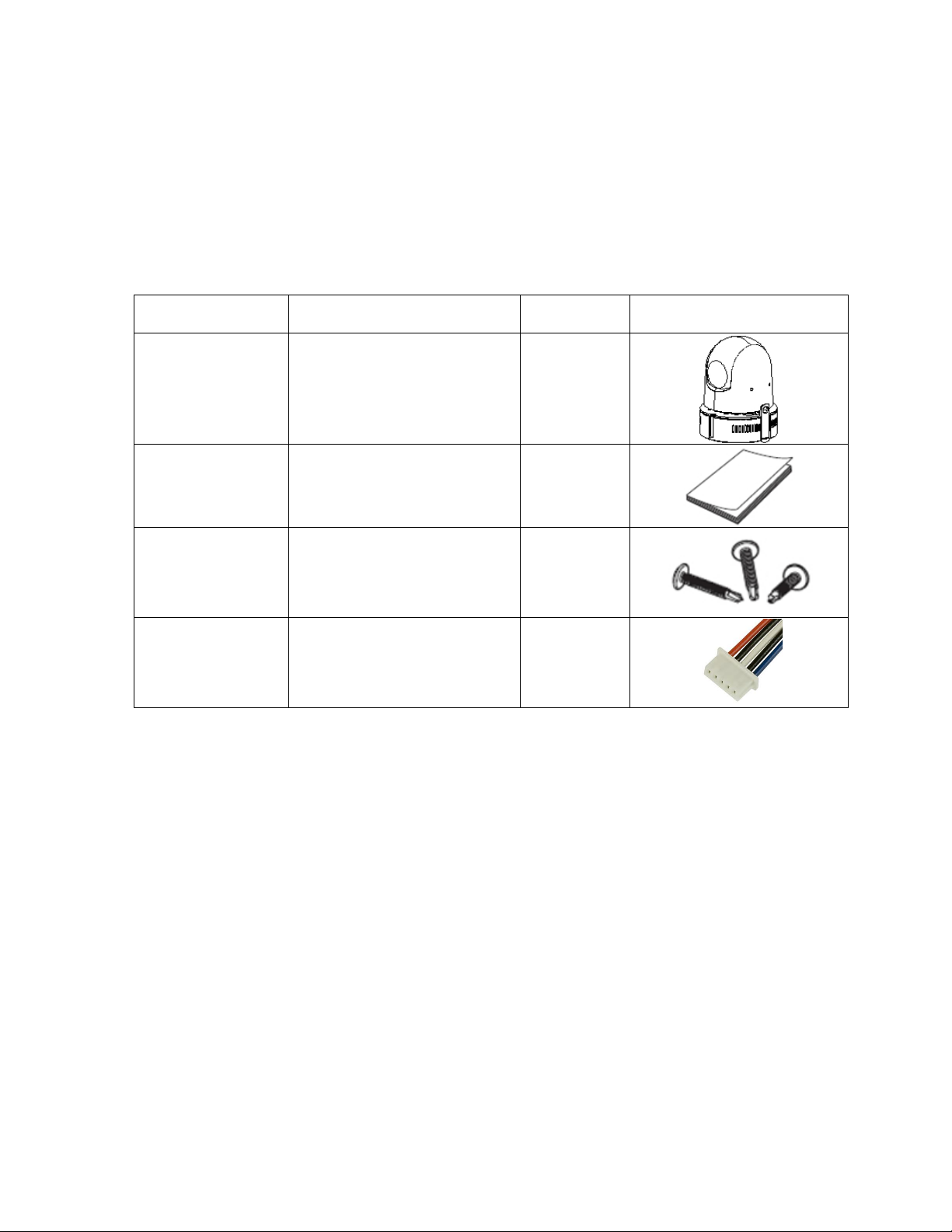
1. CONTENT VERIFICATION
Before installing the controller, please make sure that the following items are included in
the box:
If any of these materials are missing, please contact the vendor help desk immediately.
No.
Item
Quantity
Appearance
1
PTZ Dome Camera
1
2
User’s Manual
1
3
Mount Hardware
1set
4
Alarm Cable
2
Page 3
HD-SDI CAMERA
1
2. DISCLAIMER
! While every effort has been made to ensure that the information contained in this
guide is accurate and complete, no liability can be accepted for any errors or
omissions.
! Vitek reserve the right to change the specifications of the hardware and software
described herein at any time without prior notice.
! No part of this guide may be reproduced, transmitted, transcribed, stored in a
retrieval system, or translated into any language in any form, by any means, without
prior written permission of Vitek Industrial Video Products Inc.
! Vitek makes no warranties for damages resulting from corrupted or lost data due to
a mistaken operation or malfunction of the Speed Dome Cameras, peripheral
devices, or unapproved/unsupported devices.
Page 4
HD-SDI CAMERA
2
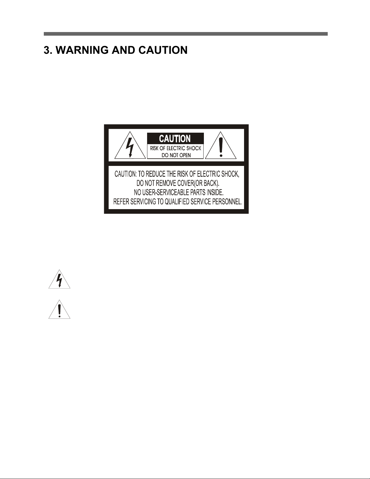
3. WARNING AND CAUTION
TO REDUCE THE RISK OF FIRE OR ELECTRIC SHOCK, DO NOT EXPOSE THIS PRODUCT TO RAIN
OR MOISTURE. DO NOT INSERT ANY METALLIC OBJECTS THROUGH THE VENTILATION GRILLS OR
OTHER OPENINGS ON THE EQUIPMENT.
EXPLANATION OF GRAPHICAL SYMBOLS
The lightning flash with arrowhe ad symbol, within a n equilateral triangle , is inte nded to
alert the user to the presence of uninsula ted "dange rous voltage " within the product's
enclosure that ma y be of sufficient m agn itude to co nstitute a risk of e le ctric shock to
persons.
The excla ma tion point within an e quilate ra l tria ngle is intended to ale rt the use r to the
pre se nce of importa nt ope rating a nd maintena nce (se rvicing) instruction in the literature
WARNING
CAUTION
accompanying the product.
Page 5
HD-SDI CAMERA
3
4. FCC COMPLIANCE STATEMENT
5. CE COMPLIANCE STATEMENT
FCC INFORMATION: THIS EQUIPMENT HAS BEEN TESTED AND FOUND TO
COMPLY WITH THE LIMITS FOR A CLASS A DIGITAL DEVICE, PURSUANT TO
PART 15 OF THE FCC RULES. THESE LIMITS ARE DESIGNED TO PROVIDE
REASONABLE PROTECTION AGAINST HARMFUL INTERFERENCE WHEN
THE EQUIPMENT IS OPERATED IN A COMMERCIAL ENVIRONMENT. THIS
EQUIPMENT GENERATES, USES, AND CAN RADIATE RADIO FREQUENCY
ENERGY AND IF NOT INSTALLED AND USED IN ACCORDANCE WITH THE
INSTRUCTION MANUAL, MAY CAUSE HARMFUL INTERFERENCE TO RADIO
COMMUNICATIONS. OPERATION OF THIS EQUIPMENT IN A RESIDENTIAL
AREA IS LIKELY TO CAUSE HARMFUL INTERFERENCE IN WHICH CASE THE
USER WILL BE REQUIRED TO CORRECT THE INTERFERENCE AT HIS OWN
EXPENSE.
CAUTION: CHANGES OR MODIFICATIONS NOT EXPRESSLY APPROVED BY
THE PARTY RESPONSIBLE FOR COMPLIANCE COULD VOID THE USER'S
AUTHORITY TO OPERATE THE EQUIPMENT.
THIS CLASS A DIGITAL EQUIPMENT COMPLIES WITH CANADIAN ICES-003.
CET APPAREIL NUMÉRIQUE DE LA CLASSE A EST CONFORME À LA NORME
NMB-003 DU CANADA.
WARNING
THIS IS A CLASS A PRODUCT. IN A DOMESTIC ENVIRONMENT THIS
PRODUCT MAY CAUSE RADIO INTERFERENCE IN WHICH CASE THE USER
MAY BE REQUIRED TO TAKE ADEQUATE MEASURES.
Page 6
HD-SDI CAMERA
4
6. IMPORTANT SAFEGUARDS
1. Read these instructions.
2. Heed all warnings.
3. Follow all instructions.
4. Do not use this equipment near water.
5. Clean only with dry cloth.
6. Do not block any ventilation openings. Install in accordance with the
manufacturer's instructions.
7. Do not install near any heat sources such as radiators, heat registers, stoves,
or other equipment (including amplifiers) that produce heat.
8. Do not defeat the safety purpose of the polarized or grounding-type plug. A
polarized plug has two blades with one wider than the other. A grounding type
plug has two blades and a third grounding prong. The wide blade or the third
prong is provided for your safety. If the provided plug does not fit into your
outlet, consult an electrician for replacement of the obsolete outlet.
9. Protect the power cord from being walked on or pinched, particularly at plugs,
convenience receptacles, and the point where they exit from the equipment.
10. Only use attachments/accessories specified by the manufacturer.
11. Unplug this equipment during lightning storms or when unused for long periods
of time.
12. Refer all servicing to qualified service personnel. Servicing is required when
the equipment has been damaged in any way, such as power-supply cord or
plug is damaged, liquid has been spilled or objects have fallen into the
equipment, the equipment has been exposed to rain or moisture, does not
operate normally, or has been dropped.
13. CAUTION - THESE SERVICING INSTRUCTIONS ARE FOR USE BY
QUALIFIED SERVICE PERSONNEL ONLY. TO REDUCE THE RISK OF
ELECTRIC SHOCK DO NOT PERFORM ANY SERVICING OTHER THAN
THAT CONTAINED IN THE OPERATING INSTRUCTIONS UNLESS YOU
ARE QUALIFIED TO DO SO.
14. Use certified / Listed Class 2 power supply only.
Page 7

HD-SDI CAMERA
5
TABLE OF CONTENTS
1. CONTENT VERIFICATION ............................................................ 0
2. DISCLAIMER ............................................................................. 1
5. CE COMPLIANCE STATEMENT ..................................................... 3
6. IMPORTANT SAFEGUARDS .......................................................... 4
7. FEATURES ............................................................................... 7
8. INSTALLATION AND CONFIGURATION ......................................... 8
8.1 TYPICAL S YSTEM C ONFIGURATION ..................................................................... 8
8.2 BASIC C ONFIGURATION OF SPEED D OME CAMERA SYSTEM ......................................... 9
8.3 L AYOUT OF SWITCHES ................................................................................. 10
8.4 PRINCIPLE OF T ERMINATION .......................................................................... 12
8.5 DOME C AMERA ADDRESS (ID) ....................................................................... 14
8.6 SYSTEM SETUP .......................................................................................... 15
8.7 C ONNECTIONS .......................................................................................... 16
8.7.1 How to Connect RS-485 .................................................................. 16
8.7 .2 Connecting Video output ................................................................. 16
8.7.3 Video Standard ............................................................................... 16
8.7.4 Video Cable .................................................................................... 16
8.7.5 Connecting Alarms .......................................................................... 17
8.7.6 Power Supply (AC/DC) .................................................................... 18
8.8 M OUNTING THE D OME CAMERA ....................................................................... 19
8.9 POWER ON AND B OOT-UP SEQUENCE ................................................................ 21
8.10 N ORMAL DISPLAY (OSD) ........................................................................... 22
9. PROGRAM & OPERATION .......................................................... 23
9.1 DOME C AMERA KEY BOARD CONTROLLER ..................................................... 23
10. FUNCTIONS ......................................................................... 24
10.1 MAIN MENU ........................................................................................... 24
10.1.1 Home Function ............................................................................. 24
10.1.2 Preset .......................................................................................... 25
10.1.2.1 Edit Title ............................................................................................................. 26
10.1.2.2 Edit Position ........................................................................................................ 26
10.1.3 Pattern ........................................................................................ 27
10.1.4 Scan ............................................................................................ 29
10.1.5 Tour ............................................................................................ 30
10.1.6 RUN FUNCTION .............................................................................. 31
10.2 Actions ........................................................................................... 32
10.2.1 Alarm Action .......................................................................................................... 32
10.2.2 Alarm List ............................................................................................................. 33
10.2.3 Clear Alarm List .................................................................................................... 34
10.2.4 Schedule Action ..................................................................................................... 34
10.2.5 Schedule Action List .............................................................................................. 38
Page 8

HD-SDI CAMERA
6
10.3 Screen ............................................................................................ 38
10.3.1 Language ............................................................................................................... 38
10.3.2 Privacy Zone .......................................................................................................... 38
10.3.3 North Direction ...................................................................................................... 40
10.3.4 Zone Title ............................................................................................................... 40
10.3.5 CAMERA TITLE ....................................................................................................... 41
10.3.6 OSD DISPLAY ......................................................................................................... 42
10.4 CAMERA SETUP ................................................................................ 43
10.4.1 AE Control (Automatic Exposure) ......................................................................... 43
10.4.2 WB Control (White Balance) .................................................................................. 46
10.4.3 Focus Control ......................................................................................................... 47
10.4.4 Night Shot .............................................................................................................. 48
10.4.5 Digital Zoom ........................................................................................................... 48
10.4.6 Gamma ................................................................................................................... 48
10.4.7 Noise Filter ............................................................................................................. 49
10.4.8 Camera Default ...................................................................................................... 49
10.5 Date/Time ....................................................................................... 49
10.6 Data ............................................................................................... 53
10.7 Setup .............................................................................................. 54
10.7.1 Preset Freeze ......................................................................................................... 54
10.7.2 Speed ..................................................................................................................... 54
10.7.3 Communication ...................................................................................................... 54
10.7.4 Dome Angle ........................................................................................................... 55
10.7.5 CALIBRATION ......................................................................................................... 56
10.7.6 Password SETUP .................................................................................................... 56
10.7.7 Installation ............................................................................................................. 57
10.7.8 Flip Offset .............................................................................................................. 57
10.7.9 System Information ............................................................................................... 57
11. APPENDIX ............................................................................ 59
11.1 SPECIFICATION .................................................................................... 59
11.2 D IMENSION ............................................................................................ 61
11. 3 TROUBLE SHOOTING .................................................................................. 62
12. GLOSSARY ........................................................................... 63
Page 9
HD-SDI CAMERA
7
7. Features
The PTZ Dome Camera features a high resolution Sony® Exmor CMOS image
sensor, That supports FULL HD (high definition) to produce high-quality images.
User friendly, on-screen pull-down menus and short-cuts make it easy to setup
and program functions.
! Built-in HD SDI driver.( SMPTE 274M, SMPTE 296M compatible.
720p/1080p)
! Built-in 20X Optical Power Zoom Camera(12X digital zoom/240X with optical
zoom).
! 248 Presets programmed with view direction, zoom, focus, and AE.
! 8 Tours consist of Preset, Pattern, Auto-Scan and other Tours can be
programmed with over 377 functions and Preset location. While moving,
each Preset scan can be watched in smooth Vector Scan mode.
! 16 Scans, 1 Auto Pan: 8speed steps from slow to medium panning with
smooth Vector Scan.
! 8 Patterns (up to 480 second).
! 16 Area Titles.
! Wide Dynamic Range Mode (WDR)
! Variable speed from 0.1°/sec to 420°/sec.
! Turbo speed is Max 420°/sec when the TURBO key is pressed.
! 8 Alarm inputs with 0~ 3 priority / 2 Auxiliary outputs programmable N.C. and
N.O.
! 8 Privacy Zones: : 4 POLYGON / V.OFF or 4 masked BLOCK / V.OFF /
MOSAIC
! Addressable up to 999 camera IDs (Extendable up to 3999 in special mode).
! Built-in RS-485 receiver driver.
! On-site firmware upgrade and upload/download of programmed data into the
KBD or base on the PTZ Dome camera. (Full function version only.)
! Built-in power-line surge protection and lightning protection.
! Optional Tinted Bubble, Indoor & Outdoor pendant housing with heater &
blower, Indoor
! Flush Mount, Parapet mount & Roof Top mount.
! Adaptive tilt limit control according to the zoom ratio provides.
! Block mode alarm preset
! On screen popup menu provides an easy way to control the dome system
using simple keyboard.
Page 10
HD-SDI CAMERA
8
8. INSTALLATION AND CONFIGURATION
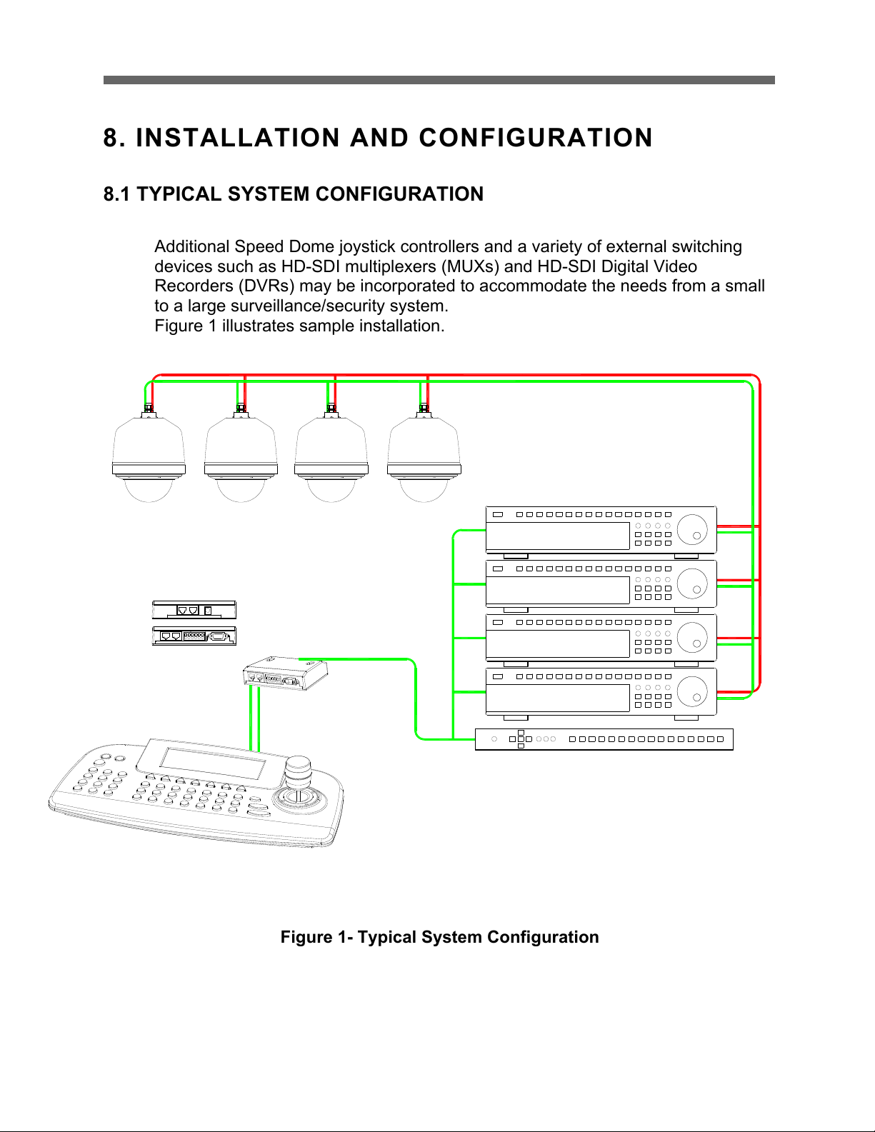
8.1 TYPICAL SYSTEM CONFIGURATION
Additional Speed Dome joystick controllers and a variety of external switching
devices such as HD-SDI multiplexers (MUXs) and HD-SDI Digital Video
Recorders (DVRs) may be incorporated to accommodate the needs from a small
to a large surveillance/security system.
Figure 1 illustrates sample installation.
Figure 1- Typical System Configuration
Page 11
HD-SDI CAMERA
9
G-+
DC 12V
DATA1
G
SLAVE KBD
DATA2
+
DOME1
-
DVR
DVR
ALARM/PC
DATA2 DATA1
STP AWG # 22
VIDEO
BNC MONITOR
J-BOX BACK
J-BOX FRONT
KEYBOARD CONTROLLER
REAR
AC 24V
POWER
HALF DUPLEX MODE
RS-485
RXB
RXA
TXA(TX+)
TXB(TX-)
CONTROLLER
DOME
COMM.(TXA/TXB)
POWER
AC 24V
AC 24V
HEATER
1 AUX OUTPUT
4 ALARM INPUT
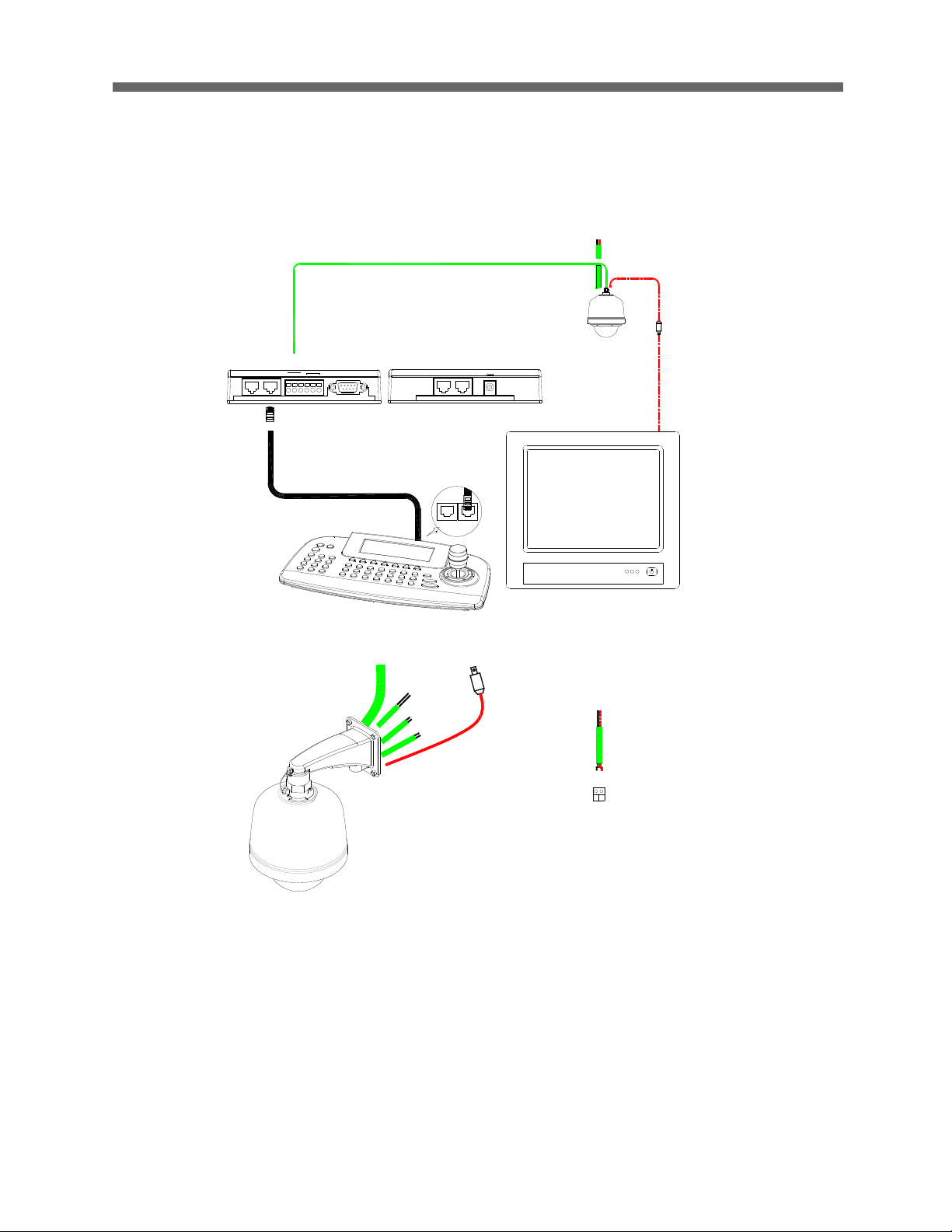
8.2 BASIC CONFIGURATION OF SPEED DOME CAMERA SYSTEM
Figure 2 - Basic Installation Diagram
Page 12
HD-SDI CAMERA
10
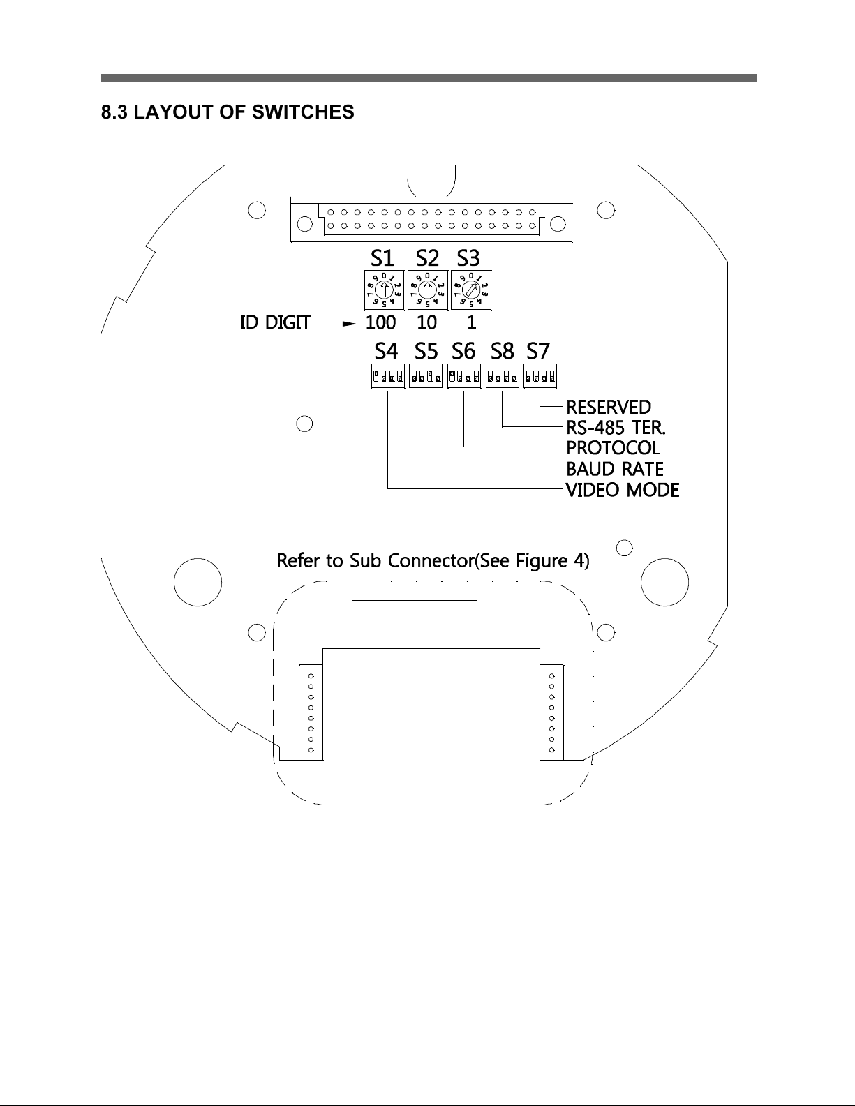
8.3 LAYOUT OF SWITCHES
Figure 3 – HD-SDI Layout of Switches
Page 13
HD-SDI CAMERA
11
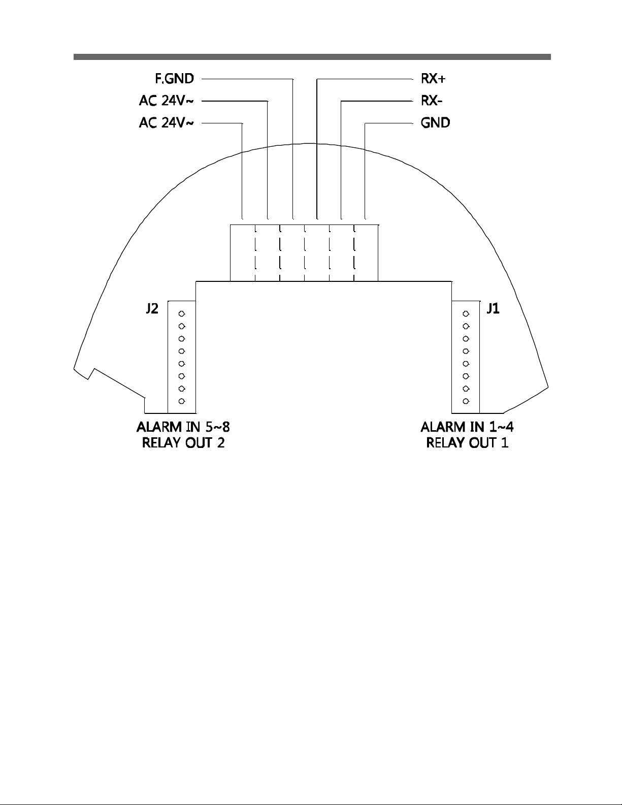
Figure 4 – HD-SDI Sub Connector
Page 14
HD-SDI CAMERA
12
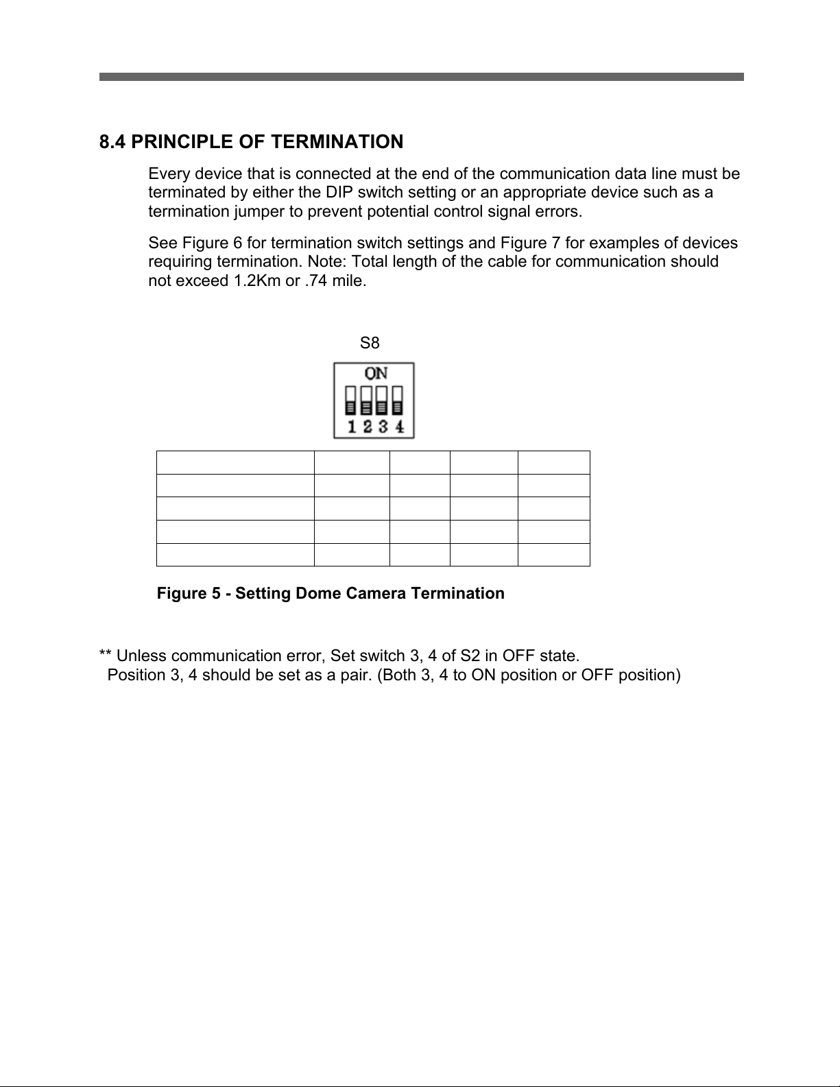
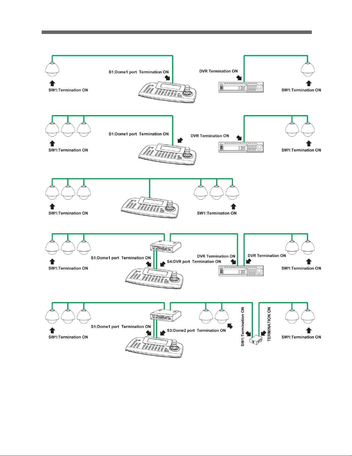
8.4 PRINCIPLE OF TERMINATION
Every device that is connected at the end of the communication data line must be
terminated by either the DIP switch setting or an appropriate device such as a
termination jumper to prevent potential control signal errors.
See Figure 6 for termination switch settings and Figure 7 for examples of devices
requiring termination. Note: Total length of the cable for communication should
not exceed 1.2Km or .74 mile.
S8
Figure 5 - Setting Dome Camera Termination
** Unless communication error, Set switch 3, 4 of S2 in OFF state.
Position 3, 4 should be set as a pair. (Both 3, 4 to ON position or OFF position)
S8: 1 2 3 4
Terminated
ON X X
X
Not terminated
OFF
X X X
Pull Up/Down **
X X ON
ON
Normal **
X
X
OFF
OFF
Page 15
HD-SDI CAMERA
13
Figure 6 - Termination Diagram
Page 16

HD-SDI CAMERA
14
8.5 DOME CAMERA ADDRESS (ID)
Each dome camera must have a unique address (ID). Identical IDs on the same
line may damage the control circuit caused by an electrical short. When
installing multiple dome cameras or a DVR, it is recommended that the dome
camera ID’s be identical to the camera port of the DVR.
Cam Port 1 = Dome ID1, Cam Port 2 = Dome ID 2 … Cam Port 16 = Dome ID 16.
If more than 16 dome cameras are installed using two or more DVRs the
following formula is useful to determine the Dome ID: ID =16x (n-1) +m (where
n= number of DVR, m=Camera Port)
Refer to Figures 8 for setting the dome camera address (ID) and protocol
DI Digit
100 10 1
S1 S2 S3
Figure 7 - Setting Dome Camera Address (ID)
DOME ID
100
10
1
1
0 0 1
.
. . .
999
9 9 9
Page 17
HD-SDI CAMERA
15
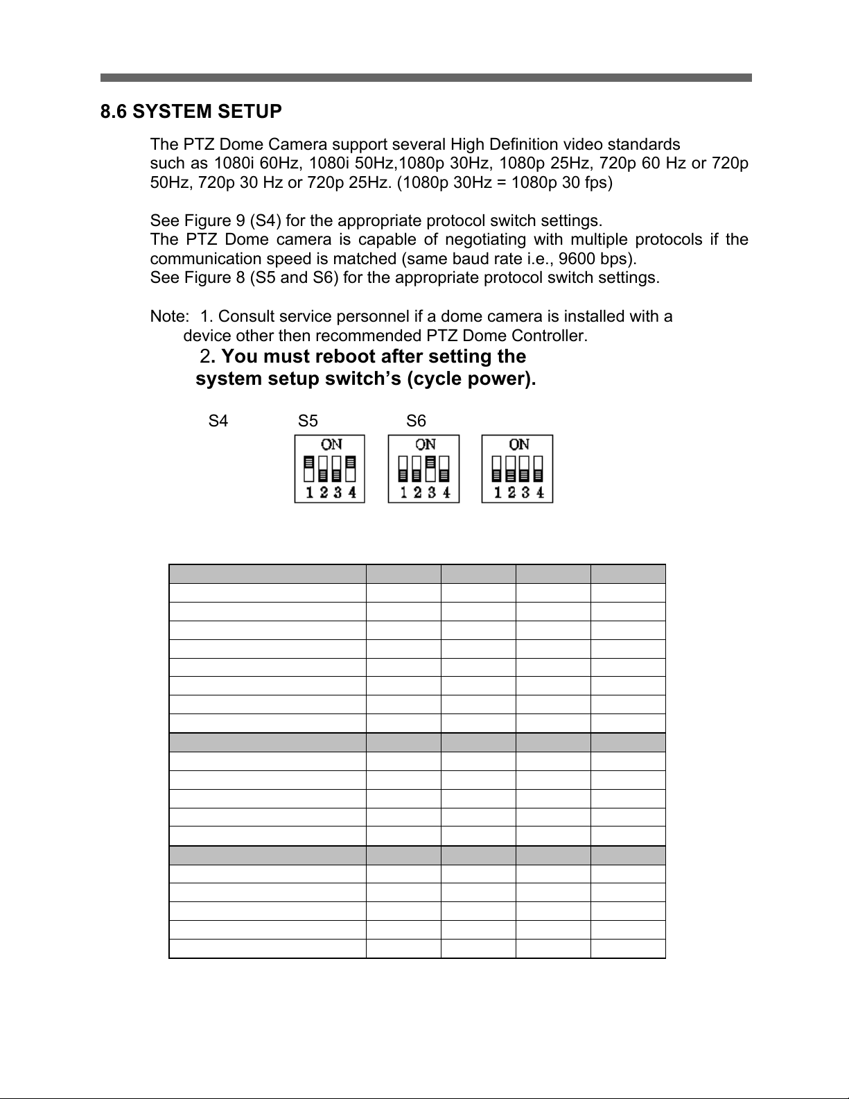
8.6 SYSTEM SETUP
The PTZ Dome Camera support several High Definition video standards
such as 1080i 60Hz, 1080i 50Hz,1080p 30Hz, 1080p 25Hz, 720p 60 Hz or 720p
50Hz, 720p 30 Hz or 720p 25Hz. (1080p 30Hz = 1080p 30 fps)
See Figure 9 (S4) for the appropriate protocol switch settings.
The PTZ Dome camera is capable of negotiating with multiple protocols if the
communication speed is matched (same baud rate i.e., 9600 bps).
See Figure 8 (S5 and S6) for the appropriate protocol switch settings.
Note: 1. Consult service personnel if a dome camera is installed with a
device other then recommended PTZ Dome Controller.
2. You must reboot after setting the
system setup switch’s (cycle power).
S4 S5 S6
Video format Baud rate protocol
Video Format S4 :
1 2 3
4
1080i 60
ON
OFF
OFF
OFF
1080i 50
ON
OFF
OFF
ON
720p 60
ON
OFF
ON
OFF
720p 50
ON
OFF
ON
ON
1080p 30
ON
ON
OFF
OFF
1080p 25
ON
ON
OFF
ON
720p 30
ON
ON
ON
OFF
720p 25
ON
ON
ON
ON
Baud Rate S5 :
1 2 3
4
2400 x OFF
OFF
OFF
4800 x OFF
OFF
ON
9600 x OFF
ON
OFF
19200
x
OFF
ON
ON
38400 x ON
OFF
OFF
Protocol S6 :
1 2 3
4
Auto Detect (No Parity)
OFF
OFF
OFF
OFF
Auto Detect (Even Parity)
OFF
OFF
OFF
ON
EZ
OFF
OFF
ON
OFF
PP
OFF
OFF
ON
ON
PD
OFF
ON
OFF
OFF
Figure 8 - Protocol Selection Tables
Page 18
HD-SDI CAMERA
16
8.7 CONNECTIONS
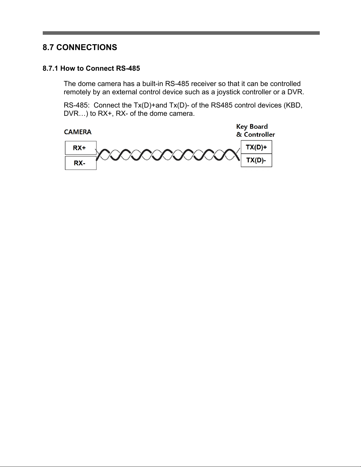
8.7.1 How to Connect RS-485
The dome camera has a built-in RS-485 receiver so that it can be controlled
remotely by an external control device such as a joystick controller or a DVR.
RS-485: Connect the Tx(D)+and Tx(D)- of the RS485 control devices (KBD,
DVR…) to RX+, RX- of the dome camera.
Figure 9 - Connection RS-485
RS-485 does not allow for a star connection layout. A splitter is required if a star
connection layout is desired. RS-485 guarantees 1.2 Km(4000 ft) of data line
routing. A repeater is recommended to extend over 1.2 Km.
8.7.2 Connecting Video output
1. In the initial installation of the camera, you can connect the camera to a HDSDI monitor to check the connection status.
2. When connecting a general monitor device with HDMI or YPbPr component
input to the HD-SDI video output, you need to use a signal converter (SDI to
HDMI or SDI to YPbPr component).
8.7.3 Video Standard
1. Countries and territories use different broadcasting television systems. to
ensure a correct video signal transmission, the appropriate video standard for
your country must be set at the device.
2. Select 1080i60/1080p30/720p60/720p30 for “NTSC countries”
3. Select 1080i50/1080p25/720p50/720p25 for “PAL countries”
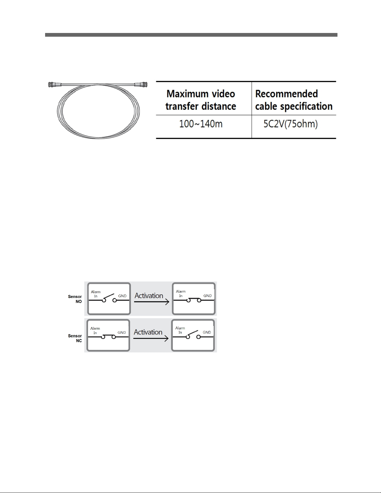
8.7.4 Video Cable
The cable connecting the camera’s video output and a monitor is a BNC
coaxial cable as shown below.
Page 19
HD-SDI CAMERA
17
If the distance between the camera and the monitor exceeds the recommended
maximum, please use an auxiliary HD-SDI Repeater.
Figure 10 – HD-SDI Video Cable
8.7.5 Connecting Alarms
Alarm In (AL1 to 8)
Magnetic, PIR or other external sensor devices can be used to signal the dome
camera to react to an event.
If you want to use alarm input, the types of sensor must be selected in OSD
menu. The sensor types are ‘Normal Open’ and ‘Normal Close’.
Select Alarm input in OSD menu
Normal Open Sensor devices: Select NO
Normal Close Sensor devices: Select NC
Alarm In activation:
N.O. ---Short circuit between GND and Alarm Input pin
N.C. ---Open circuit between GND and Alarm Input pin
Alarm Out 1,2
If you want to use alarm Output, the Number of output “1” and “2” must be
selected in OSD menu.
1. Alarm out “1” in OSD menu
2. Alarm out “2” in OSD menu
Page 20
HD-SDI CAMERA
18
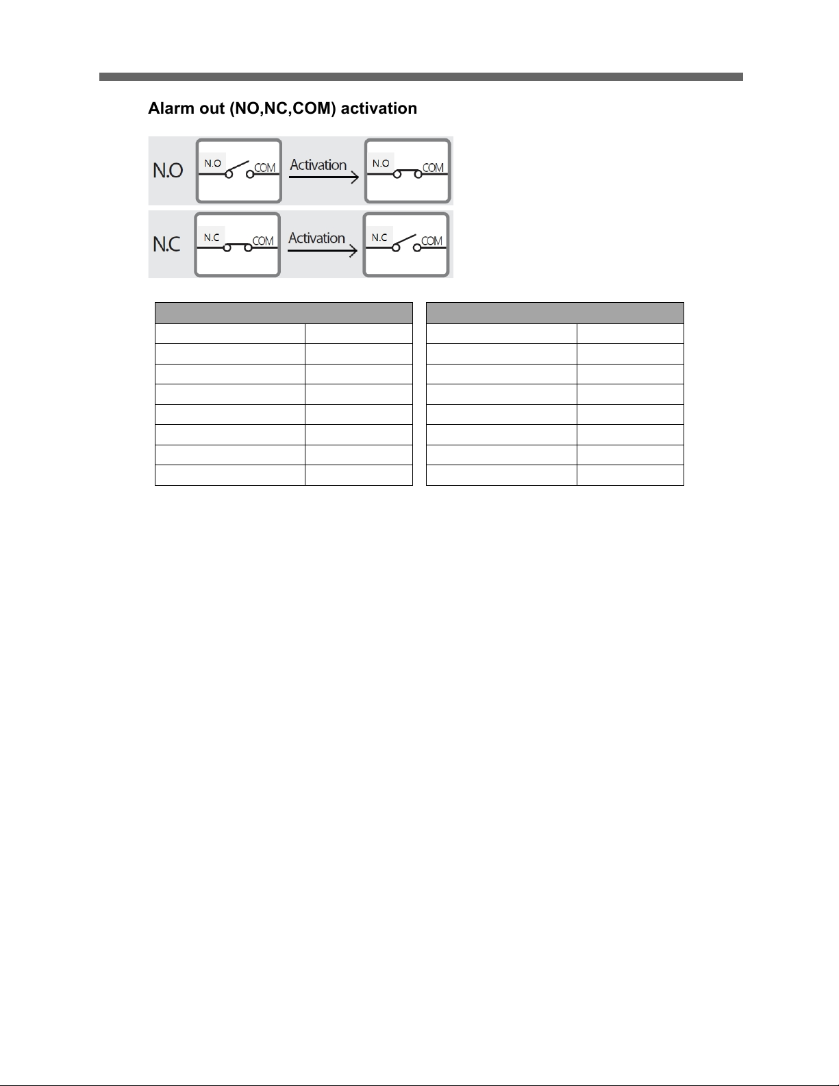
Alarm out (NO,NC,COM) activation
Figure 11 - Alarm Cable assignment
GND (Ground)
NOTE: All the connectors marked GND are common.
Connect the ground for the Alarm input and /or alarm output to the GND
connector.
NO / NC (Normal Open or Normal Close /Contact Relay Output)
The dome camera can activate external devices such as buzzers or lights using
dry contact relays. Connect the device to the NO (NC) (Alarm Out) and COM
(Common) connectors. (See Figure 5 /12)
8.7.6 Power Supply (AC/DC)
You can use either AC 24V/2A or DC 12V/2A adaptor.
Use certified / Listed Class 2 power supply Only.
J1: Alarm1(part A)
J2: Alarm2 (part B)
Black
Alarm1
Black
Alarm5
Brown
Alarm3
Brown
Alarm6
Red
Alarm3
Red
Alarm7
Orange
Alarm4
Orange
Alarm8
Yellow
A1 GND
Yellow
A2 GND
Green
COM A
Green
COM B
Blue
NC A
Blue
NC B
Gray
NO A
Gray
NO B
Page 21
HD-SDI CAMERA
19
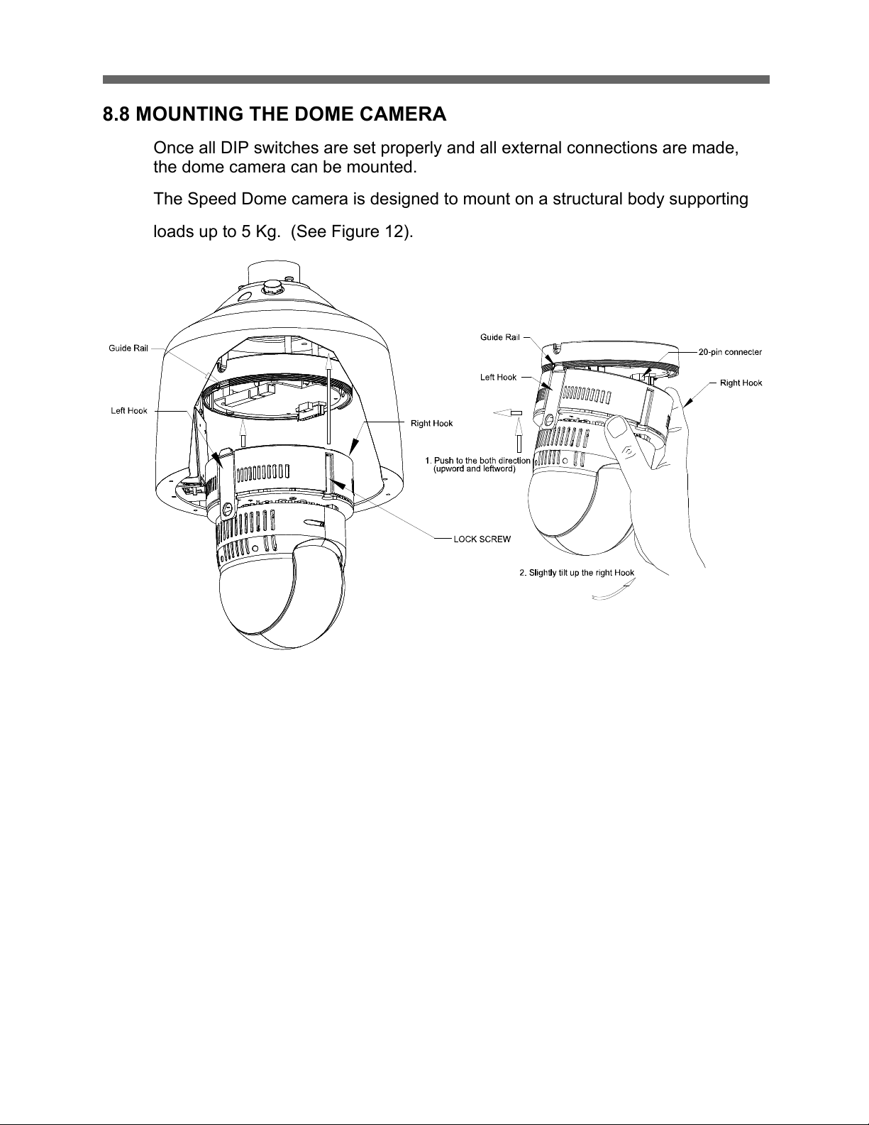
8.8 MOUNTING THE DOME CAMERA
Once all DIP switches are set properly and all external connections are made,
the dome camera can be mounted.
The Speed Dome camera is designed to mount on a structural body supporting
loads up to 5 Kg. (See Figure 12).
Figure 12 - Example of a ceiling mounted installation
Page 22

HD-SDI CAMERA
20
1
1
2
2
3
Figure 13 - Example of a Surface mounted installation
Page 23

HD-SDI CAMERA
21
8.9 POWER ON AND BOOT-UP SEQUENCE
When the power is applied to the PTZ dome camera, it will start the boot-up
sequence. When boot-up is done, the following information is displayed on the
monitor screen.
The boot-up sequence displays information of the PTZ dome camera for service
or trouble shooting purposes.
H/W Ver. Hardware version
S/W Ver. Software version
FPGA Ver. Version of FPGA (Field Programmable Gate Array)
ID ID of PTZ dome camera
Baud rate Baud rate
Protocol Protocol type
Tilt Test report of tilt mechanism
Pan Test report of pan mechanism
Camera Type of camera module
H/W Ver. :V1.0
S/W Ver. :V1.45C
FPGA Ver. :V1.1
ID Ver. :0001
Baud rate :9600 bps
Protocol :AUTO
Tilt :Origin set OK
Pan :Origin set OK
Page 24

HD-SDI CAMERA
22
8.10 NORMAL DISPLAY (OSD)
After a successful boot-up sequence the following information can be displayed
on the monitor screen.
On Screen Display in normal control mode
00/00/0000 00:00:00 AM Date and time
(Function Title) PRESET / SCAN / PATTERN / TOUR
AF AE Focus mode, Exposure mode
MESSAGE Status messages (e.g. of memory usage)
ALARM:123 Activated alarm input number
20.0X Zoom magnification
270.0,090.0 Angles of PAN, TILT
"N Approximate view direction, e.g. (→N)North
DOME ID Title of PTZ dome camera (up to 8 characters)
0001 ID of PTZ dome camera
1. Control the Joystick ( left /right) for panning.
2. Control the Joystick (up/down) for tilting.
3. Control the TELE to zoom in.
4. Control the WIDE to zoom out.
5. Press the IRIS OPEN button to open the iris.
6. Press the IRIS CLOSE button to close the iris.
7. Press the IRIS OPEN FAR button for far focusing.
8. Press the IRIS OPEN NEAR button for near focusing.
00/00/0000 00:00:AM
(Function Title) AF AE
Message
ALARM:123
Page 25

HD-SDI CAMERA
23
9. PROGRAM & OPERATION
9.1 DOME CAMERA KEY BOARD CONTROLLER
Prior to programming or operating a dome camera, please make sure that both
the camera and the joystick controller are communicating. In order for changes
to take effect for a camera, particular camera’s ID must be selected on the
controller.
Example: Pressing 1,6 and CAM key sequentially will select dome camera 16.
The selected dome camera ID will be displayed on the monitor.
Principle of joystick usage in the programming (editing) mode
Button or Joystick movement in menu
Function
JOYSTICK + left or right
Go into the sub-menu items.
Execute the command(exit)
Change value.
Navigate through the menu items.
JOYSTICK + up or down
Navigate through the menu items.
JOYSTICK + down
Finish editing title.
JOYSTICK + Tele/Wide
Change value.(Increase / Decrease)
Enter editing title mode.
JOYSTICK + SHIFT
PTZ control mode
ESC
Escape from the menu without change
HOME or OFF button
Delete value or name of the field.
Page 26

HD-SDI CAMERA
24
10. FUNCTIONS
10.1 MAIN MENU
By pressing the MENU button on the keyboard controller, the following On-
screen Main Menu will be shown on the monitor screen.
10.1.1 Home Function
After Home item has been selected, follow the directions below to set Home
function.
# Function : Preset/ Pattern/ Scan/Tour
HOME FUNCTION
Function : PRESET
Number : 001
Waiting Time : 060 sec
Enable : OFF
Save and Exit
FUNCTION MENU
Home Function
Preset
Pattern
Scan
Tour
Main Menu
Function
Action
Screen
Camera
Date/Time
Data
Setup
Page 27

HD-SDI CAMERA
25
# Number : - - -
# Waiting Time : 10~240 Seconds
# Operation : Enable/ Disable
The Home function applies to the predefined functions such as Preset, Tour,
Pattern, or Scan function after the keyboard controller has been idle for a
programmed time.
Follow the steps below to program the Home function:
1. Select the camera number by pressing No. and CAM
2. Press MENU to display the main menu on the monitor.
3. Twist the Joystick to CCW/CW on “Functions”.
4. Enter Home Function menu by twisting the Joystick to CCW/CW.
5. Moving the Joystick to the right/ left (or twist CCW/CW) to scroll Tour, Pattern, and
Auto Scan and Preset functions.
6. Select Function Number by pulling the Joystick down, and twist the Joystick to the
CCW/CW (or turn right/left). The executable function number will be scrolled. If
selected function is not programmed, it won’t change. Go to setup function first.
7. Pull the Joystick down and twist the Joystick to CCW/CW (or twist the joystick to
right/left) to set waiting time.
8. Highlight Operation option by pulling the Joystick down. Choose operation status
Enable or Disable by moving the Joystick to the right or to the left (or twist
CCW/CW).
10.1.2 Preset
A Position preset stores pan, tilt, zoom and focusing positions with predefined
camera presets. Position presets can be call directly, assigned to actions or
applied as “HOME” position.
(Not Defined) Means No Position Preset stored with this number
PRESET SETUP
Number : 001(Defined)
Title : ---------Edit Position
AE Control
WB Control
Focus Control
Night Shot
Gamma : Gamma1
Page 28

HD-SDI CAMERA
26
1. Edit the title of the Position Preset (see section 10.1.2.1.Edit Title).
2. Edit the camera position (see section 10.1.2.2. Edit Position).
3. Edit the camera AE settings (see section 10.4.1. AE Control).
4. Edit the camera WB settings (see section 10.4.2. WB Control).
5. Edit the camera Focus settings (Auto/One Push/Manual).
6. Edit the camera Night Shot settings (see section 10.4.4. Night Shot Setup).
7. Edit the camera Gamma settings (see section 10.4.6. Gamma).
8. Edit the camera Noise Filter settings (OFF/1~5).
9. Execute Save and Exit to save the settings and exit the submenu.
To run a stored position preset directly from the dome menu, go to Run Function
in the main DOME MENU.
10.1.2.1 Edit Title
Open the Title menu.
An alphanumeric character table is displayed on the monitor screen.
Blinking cursor (P) Digit position
Yellow cursor (P) Current cursor position
1. Move the cursor with the joystick to select a digit position in the title line.
2. Move the cursor with the joystick to a character in the character table.
3. Control the joystick (TELE/WIDE) to set the selected character.
The cursor in the title line moves to the next digit position automatically.
To delete all characters, select and execute Delete All.
4. Execute Save and Exit with Control the joystick(TELE/WIDE)
10.1.2.2 Edit Position
1. Open the Edit Position menu.
EDIT TITLE
PRESET1
123456790 Space
ABCDEFGHIJ Backspace
KLMNOPQRST Insert
UVWXYZ()-/ Delete
Abcdefghij Delete All
Page 29

HD-SDI CAMERA
27
123.0,100.0 Angles of PAN,TILT
10.X X Zoom magnification
1. Edit the position (joystick up/down/left/right) and the zoom factor
(TELE/WIDE)
2. Press the IRIS-OPEN button to save the settings.
10.1.3 Pattern
A pattern records a user-defined series of pan, tilt, zoom and focus movements.
Up to 8 patterns can be programmed for the PTZ dome camera.
Patterns can be called directly, assigned to actions or applied as “home” position.
1. Select a pattern item.
If column SEC is not 000, a recording is already saved at the selected pattern
PATTERN SETUP
NO TITLE SEC
01 PATTERN1 000
02 PATTERN2 000
03 PATTERN3 000
04 PATTERN4 000
05 PATTERN5 000
06 PATTERN6 000
07 PATTERN7 000
08 PATTERN8 000
PRESET POSITION SETUP
CONTROL
Page 30

HD-SDI CAMERA
28
number.
2. Move the cursor position with Joystick (up/down)
3. Select the column number(01)
4. Control the Joystick(tele/wide) to Open the PATTERN AREA SETUP menu
The recording starts.
1. Scan the relevant area.
2. Press the IRIS-OPEN button to save the recording.
The PATTERN SETUP is displayed again.
3. Select the column TITLE and then control the joystick(tele/wide)
4. Edit the title of the pattern (see section 10.1.2.1 Edit Title).
If the total recording time reaches 480 seconds, the recording is stopped
automatically.
When you start to record again, the previous data will be overwritten.
5. Execute Save and Exit.
To run a stored pattern directly from the dome menu, go to Run Function in the
PATTERN SETUP
NO TITLE SEC
01 PATTERN1 045
02 PATTERN2 000
03 PATTERN3 000
04 PATTERN4 000
05 PATTERN5 000
06 PATTERN6 000
07 PATTERN7 000
08 PATTERN8 000
PATTERN AREA SETUP
CONTROL
1 :000 SEC
Total :000 SEC
Press IRIS-OPEN to save
Page 31

HD-SDI CAMERA
29
main DOME MENU.
10.1.4 Scan
The scan function enables the PTZ dome camera to move automatically
between two user-defined positions at different speeds. This is very helpful if
monitoring certain areas frequently.
Scans can be called directly, assigned to actions or applied as “home” position.
Number 01–16
Title Up to 16 characters
Mode Normal: Move from start point to end point in panning only
Diagonal: Move from start point to end point including tilt and zoom
simultaneously and linearly
Speed 1– 8 Level (1: slower, 8: faster)
Dir Scan direction: CCW (Counter Clock Wise) CW(Clock Wise)
Start Set Start point
End Set End point
Swap Swaps the start point for the end point if
Enabled (ON)
Dwell Dwell time at the start and end point, 03– 99
seconds
1. Select a number for the scan.
2. Edit the title of the scan (see section 10.1.2.1 Edit Title).
3. Select the scan mode.
4. Select the scan speed.
5. Edit the position of the start and end point (see section 10.1.2.2 Edit
Position”).
6. Set the scan direction.
SCAN SETUP
Number :01
Title :SCAN1
Mode :Normal
Speed :3 LEVEL
Start :None
End :None
Dir :ccw
Swap :OFF
Page 32

HD-SDI CAMERA
30
7. Set the swap option.
8. Set the dwell time.
9. Execute Save and Exit.
To run a stored scan directly from the dome menu, go to Run Function in the
main DOME MENU.
10.1.5 Tour
Tours can be called directly, assigned to actions or applied as “home” position.
8 programmable tours are available Each tour can consist of up to 42
functions (preset, pattern, scan or other tour). Using second-level tours, it can be
expanded up to 336 functions in a single tour. However, tours in the second-level
tour will be ignored when called by the first-level tour. This can be best illustrated
by the following example:
If Tour 01: Preset 02, Preset 03, Tour 02, Tour 03
Tour 02: Preset 05, Preset 06, Tour 04, Preset 05
Tour 03: Preset 07, Pattern 01
Tour 04: Preset 08, Preset 05, Pattern 01
Tour 01 executes as follows:
Preset 02 -> Preset 03 -> Preset 05 -> Preset 06 -> Preset 05 -> Preset 07 ->
Pattern 01 ... (Tour 04 in Tour 02 will be skipped in Tour 01)
Tour 02 executes as follows:
Preset 05 -> Preset 06 -> Preset 08 -> Preset 05 -> Pattern 01 ->
Preset 05 …(Tour 04 is still valid if called directly from Tour 02)
Page 33

HD-SDI CAMERA
31
TOUR No :Tour number
Title :16 characters
FUNC ---- :Blank function
:PRST : Preset 1–248
:PTRN : Pattern 1–8
:SCAN : Scan 1–16
:TOUR : Tour 2–8
NO : Function number
SP(speed) VF: Normal Mode and Velocity Fast
V1–V8: Diagonal mode and Velocity 1 (low) to 8 (high)
DW(ell) Dwell time: 03– 99sec
TITLE Displays 16 characters of the predefined function title
1. Select a number (No) for the tour.
2. Edit the title of the tour (see section 10.1.2.1 Edit Title).
3. Select a blank location (----) and set the function type (FUNC).
4. Select the predefined function number (NO).
5. Select the speed (SP) and the dwell time (DW).
6. Execute Save and Exit.
To run a stored tour directly from the dome menu, go to Run Function in the main
DOME MENU.
10.1.6 RUN FUNCTION
This Run Function menu allows you to execute the function when you use a
keyboard without the function keys (Preset/Pattern/Scan/Tour/Home/ Auto
Pan/Alarm out).
TOUR MENU 01/06
TOUR No :01
Title:TOUR1
FUNC NO SP DW TITLE
---- -- -- -- ----------------
---- -- -- -- ----------------
---- -- -- -- ----------------
---- -- -- -- ----------------
---- -- -- -- ----------------
---- -- -- -- ----------------
---- -- -- -- ----------------
Page 34

HD-SDI CAMERA
32
Function : Preset/Pattern/Scan/Tour/Home/ Auto Pan/Alarm out
Number : Function Number
Action : ON, OFF (ALARM OUT only)
Follow the steps below to program the Run Function:
1. Select the desired Function and Number.
2. Select the desired Action to ON or OFF (for ALARM OUT).
3. Select “Run” and push Joystick left / right to execute the selected function.
NOTE: To execute the function, you should save the function
(Preset/Pattern/Scan/Tour/Home/ Auto Pan/Alarm out) first.
10.2 Actions
The ACTION SETUP allows you to configure the alarm functionality and to
schedule the automatic execution of a function.
10.2.1 Alarm Action
Select the Alarm Action
ACTION SETUP
Alarm Action
Alarm List
Clear Alarm List
Schedule Action
Schedule Action List
RUN FUNCTION
Function : ------------Number : ---Action : ---
Run
Page 35

HD-SDI CAMERA
33
NO Alarm input number
FCT Function Type: PRESET, PATTERN, TOUR, SCAN, HOME
FCT No Number of Function
IN NO (Normally Open)
NC (Normally Closed)
OFF: Ignore
OUT Select (Relay out 1,Relay out 2)
PRI Priority 0~3
Lower No. has higher priority, Equal priority alarms will be serviced
repeatedly.
DWL Dwell time(0~120 sec)
10.2.2 Alarm List
# DATE : displays according to the date format.
ALARM LIST
NO DATE TIME ALARM
Previous Next
Exit
ALARM ACTION SETUP
NO FCT FCT No IN OUT PRI DWL
01 --- --- OFF OFF 1 --02 --- --- OFF OFF 1 --03 --- --- OFF OFF 1 --04 --- --- OFF OFF 1 --05 --- --- OFF OFF 1 --06 --- --- OFF OFF 1 --07 --- --- OFF OFF 1 --08 --- --- OFF OFF 1 ---
Page 36

HD-SDI CAMERA
34
# TIME : displays in 24 Hour format only.
# The alarm list displays the date and time, and alarm input number up to 80
alarms.
# Push the Joystick right or left at the “Previous Next” to see the next numbers.
# A001 :means the alarm occurs at alarm input 1.
* This list is not cleared by the factory default operation.
10.2.3 Clear Alarm List
Select “YES” to clear the alarm list.
10.2.4 Schedule Action
The schedule action setup allows you to program to act the function as below at a
specific date and time
Action Number Up to 99
Function Type PRESET, SCAN, PATTERN, TOUR, AUTO PAN, ALARM
OUT, ALARM IN, D/N:BW, D/N:COLOR, D/N:AUTO
Function Number Number of Function Type
Function Status ON, OFF (ALARM OUT only)
Action Active YES, NO
Clear Alarm List
Are you sure ?
YES >
SCHEDULE ACTION SETUP
Action Number :02
Function Type :---Function Number :--Function Status :--Action Active :NO
Action Title :
Action Day :HSMTWTFS
Start Time :00:00:AM
Add Action To List
Page 37

HD-SDI CAMERA
35
Action Title Up to 12 characters (see section 10.1.2.1 Edit Title)
Action Day ON : H(Holiday) S(Sunday) M(Monday) T(Tuesday)
W(Wednesday) T(Thursday) F(Friday) S(Saturday)
OMIT : O(Holiday) (see section 10.5 Date/Time)
Start Time hh:mm, AM/PM
Add Action To List Add the current action to the list.
Delete Action Delete the current action from the list.
1. Select a number for the action.
2. Select the function type which should be executed automatically.
3. Select the function number which should be executed automatically.
4. Select the function status (at Function Type: ALARM OUT only).
5. Set the action to active or inactive (Action Active: YES/NO) as required.
6. Edit the action title (see section 10.1.2.1 Edit Title).
7. Select the action day(s) when to execute the selected function automatically
(see section 10.5 Date/Time).
8. Set the start time when to execute the selected function automatically.
9. Execute Add Action To List.
10. Select YES to add the current action to the list.
To edit a stored action, select the relevant action number and edit the relevant
options.
To delete a stored action, select the relevant action number and execute Delete
Action.
Add Action to List
Are you sure ?
YES >
Page 38

HD-SDI CAMERA
36
1. Select YES to delete the action from the list.
Note: That a scheduled action has no duration. Therefore, you should set
a second action to end the previous action.
For example, suppose you want to operate the camera in black and white mode
after 10:00pm and in Day/Night auto mode from 06:00am every day:
First, program an action with the settings D/N:BW at 10:00 PM every day.
Second, program another action with the settings D/N:AUTO at 06:00 AM every
day.
If you program the first action only, the camera always operates in black and
white mode.
So do not forget to program a second action for the Day/Night and the Alarm Out
options.
The function types D/N:COLOR, D/N:BW and D/N:AUTO change the camera
setup configuration and do not affect a preset. So we recommended to set
another preset for the night.
Delete Action
Are you sure ?
YES >
Page 39

HD-SDI CAMERA
37
Edit Day
HOLIDAY:
OMIT : The action will not occur on a day of the week for which it is set
If that date is in the list of holidays (see section 10.5 Date/Time)
ON : The action will occur on a day of the week for which it is set if
that date is in the list of holidays.
OFF : The action only occurs on a day of the week for which it is set.
Holidays have no effect on the action.
SUNDAY – SATURDAY
ON : The action will occur on a day of the week for which it is set.
OFF : The action will not occur on that day of the week.
All On Sets all days to ON for your convenience.
All Off Sets all days to OFF for your convenience.
1. Select the relevant day.
2. Select the relevant option.
3. Execute Save and Exit.
EDIT DAY
HOLIDAY :ON
Sunday :ON
Monday :ON
Tuesday :ON
Wednesday :ON
Thursday :ON
Friday :ON
Saturday :ON
All on
Page 40

HD-SDI CAMERA
38
10.2.5 Schedule Action List
LIST ACTION ALL, PRESET, SCAN, PATTERN, TOUR, AUTOPAN,
ALARM OUT, ALARM IN, D/N:BW, D/N:COLOR, D/N:AUTO
1. Select the LIST ACTION type to sort the action list. Ø
2. Select Previous or Next to list previous or next actions.
10.3 Screen
10.3.1 Language
Preferred language will be scrolled by moving the joystick to the right on
Language ENGLISH.
10.3.2 Privacy Zone
To ensure privacy protection and compliance with laws and regulations that
prohibit certain locations from being monitored and/or recorded, the PRIVACY
LIST ACTION :ALL >
01: ACTION ACTIVE
HSMTWTFS 00:01 AM PRESET 001
SCREEN MENU
Language
Privacy Zone
North Direction:000.0
Zone Title
Camera Title
OSD Display
Page 41

HD-SDI CAMERA
39
ZONE SETUP allows you to hide (mask) up to 8 user-definable areas in the
camera.
TITLE Up to 16 characters
METHOD No. 01~04 methods only None, V.OFF, and POLYGON are
selectable.
No. 05~08 methods only None, BLOCK, V.OFF (Video off),
MOSAIC are selectable.
COLOR BLU (Blue), PUR (Purple), RED, YEL (Yellow),
CYA (Cyan), GRN (Green), MAG (Magenta), WHT (White)
GRY (Grey)
ZT Zoom Trigger
1. Select a privacy zone number (No.)
2. Control the joystick (tele/wide) to enter the PRIVACY AREA SETUP.
3. Edit the position and the zoom factor to set the privacy zone area.
4. Press the IRIS_OPEN button
5. Edit the mask position and Press the IRIS_OPEN button
6. Adjust the mask size with joystick (left/right/up/down)
7. At the polygon mode in order to make each corner of a quadrangle Press
the IRIS_OPEN button
8. Press the IRIS_OPEN button to save the settings.
PRIVACY AREA SETUP
CONTROL
Press IRIS-OPEN to Polygon mode
PRIVACY ZONE SETUP
NO TITLE METHOD COLOR ZT
01 None BLU OFF
02 None BLU OFF
03 None BLU OFF
04 None BLU OFF
05 None BLU OFF
06 None BLU OFF
07 None BLU OFF
Page 42

HD-SDI CAMERA
40
1. Select the TITLE of the privacy zone.
2. Control the joystick(tele/wide) to edit the privacy zone title
(see section 10.1.2.1 Edit Title).
3. Select the METHOD for the privacy zone masking.
If the selected METHOD is BLOCK, select the required color for the privacy
zone masking.
4. Select the COLOR for the privacy zone masking color
5. Execute Save and Exit.
Note that the privacy zone is not displayed in the OSD configuration mode.
10.3.3 North Direction
ON :Sets current direction as →N and the coordinate angle to 000.
OFF Hides the directional title
Every 90° of clockwise rotation will change the title to:
> E (East),
> S (South),
> W (West)
If using the ON/OFF option frequently, it is recommended that you set “North” as
a preset. Recall the “North” preset before enabling the directional title.
10.3.4 Zone Title
The ZONE TITLE SETUP allows the assignment of specific names for
programmed
camera angles between start and end position.
Thus, for example, for the screen shown below, “ABC” is displayed on the screen
when the camera is positioned between 124.3° and 359.5° under 90° vertically.
Page 43

HD-SDI CAMERA
41
1. Select an Area Title item.
2. Select the Start angle field.
3. Control the Joystick (tele/wide) to edit the start position.
4. Edit the start position.
5. Press the IRIS-OPEN to save the settings.
6. Select the End angle field.
7. Control the Joystick (tele/wide) to edit the end position.
8. Edit the end position.
9. Press the IRIS-OPEN to save the settings.
10. Select the Title (or Number) field.
11. Control the joystick (tele/wide) to edit the area title (see section 10.1.2.1 Edit
Title).
12. Execute Save and Exit.
13. Select Previous or Next to list previous or next area titles.
If the PTZ dome camera is positioned over 90° vertically, first move the PTZ
dome camera to 90° vertically. Otherwise, the PTZ dome camera moves to 90°
vertically automatically when you edit the position.
10.3.5 CAMERA TITLE
This function allows the users to set the title of camera as well as the usage of on
screen display of the title.
Twist the joystick handle on the Camera Title. Refer to the preset title
Zone TITLE SETUP 01/03
NO Title Start End
01 ----- ----02 ----- ----03 ----- ----04 ----- ----05 ----- ----06 ----- ----07 ----- ----08 ----- -----
Page 44

HD-SDI CAMERA
42
1. Blinking cursor (D) Digit position
Yellow cursor (D) Current cursor position
10.3.6 OSD DISPLAY
Available settings:
OFF Label is not displayed when activated.
ON Label is permanently displayed when activated.
2, 5, 10sec Label is displayed for the selected seconds after Activation.
For the Date/Time options only ON and OFF are selectable.
EDIT TITLE
DOME ID
123456790 Space
ABCDEFGHIJ Backspace
KLMNOPQRST Insert
UVWXYZ()-/ Delete
Abcdefghij Delete All
Klmnopqrst Exit
DISPLAY SETUP
DOME ID :ON
DOME Title :ON
Position :ON
Area Title :ON
Action Title :ON
Function Title :ON
Focus,Exposure :ON
Zoom :ON
Date/Time :ON
North Direction:ON
Page 45

HD-SDI CAMERA
43
10.4 CAMERA SETUP
10.4.1 AE Control (Automatic Exposure)
Mode
AUTO:
Auto Iris and Gain, Fixed Shutter speed.
The gain and shutter speed are set automatically, according to the brightness
of the subject.
MANUAL:
Variable Shutter, Iris and Gain.
The shutter speed, iris and gain can be set freely by the user.
SHUTTER:
Variable Shutter Speed, Auto Iris and Gain.
(1/1 to 1/10,000 sec., 16 high-speed shutter speeds.
plus 6 low-speed shutter speeds)
Flicker can be eliminated by setting shutter to -1/100s for NTSC models
AE CONTROL
Mode :AUTO
Iris :F2.8
Gain :odB
Shutter :1/60
Exposure Compensation :0
Slow Shutter :AUTO
Back Light Comp. :Off
Bright :10
Sharpness :9
CAMERA SETUP
AE Control
WB Control
Focus Control
Night Shot
Digital Zoom : OFF
Gamma : STADNDARD
Noise Filter : OFF
Camera Default
Page 46

HD-SDI CAMERA
44
used in countries with a 50 Hz power supply frequency.
- 1/120s for PAL models used in countries with a 60 Hz power supply frequency.
IRIS:
Iris priority mode
Variable Iris (F1.6 to Close, 18 steps),
Auto Gain and Shutter speed.
BRIGHT:
Variable Iris and Gain (Close to F1.6, 17 steps at 0dB:F1.6, 15 steps from 0 to 28
dB) according to the brightness level.
Exposure is controlled by Iris when bright and by Gain when dark.
When switching from the SHUTTER priority mode to the BRIGHT mode, the
current status will be retained for a short period of time.
Iris
The iris can be set freely by the user to 18 steps between F1.6 and Close.
The gain and shutter speed are set automatically,
ccording to the brightness of the subject.
Gain
0 / 2 / 4 / 6 … / 28dB
Defines the maximum amount of electrical gain with which the amplitude of the
incoming signal is increased.
Useful in low light situations.
The higher the gain is set the more image noise may occur.
Shutter
Shutter speeds (22 steps) : 1/1, 1/2, 1/4(3), 1/8(6) ... 1/4000(3500), 1/6000,
1/10000sec
Slow shutter speeds : 1/1, 1/2, 1/4(3), 1/8(6), 1/15(12), 1/30(25)
Values in () stand for 50Hz mode cameras.
Slow shutter speeds are useful in low light conditions, but may result in motion
blur with fast moving objects.
$ Note:
When slow shutter speeds are used, Auto Focus and White Balance may not
function fully.
Exposure Compensation
−7 to +7 (−10.5dB to +10.5dB)
Exposure compensation is a function which offsets the
internal reference brightness level used in the AE mode, by steps of 1.5 dB.
Slow Shutter : ON/OFF(AUTO mode only)
Page 47

HD-SDI CAMERA
45
Back Light Compensation
Back light compensation: ON / OFF
Compensates for the silhouetting effect of backlit objects (e.g. in front of windows,
glass doors or other sources of light).
When the background of the subject is too bright, or when the subject is too
dark due to shooting in the AE mode, back light compensation will make the
subject appear clearer.
Selectable in AUTO mode only.
Bright
0, 1, 2, 3, 4 ... 31
Defines the brightness level.
The bright control function adjusts both gain and iris using an internal algorithm,
according to a brightness level freely set by the user. Exposure is controlled by
gain when dark, and by iris when bright.
Sharpness
Higher the value, outlines of the image will be enhanced (0~15).
WDR (Wide Dynamic Range)
The Wide Dynamic Range mode is a function for dividing an image into several
blocks and correcting blocked-up shadows and blown-out highlights in
accordance with the intensity difference. It enables you to obtain images in which
portions ranging from dark to light can be recognized, even when capturing a
subject with a large intensity difference that is backlit or includes extremely light
portions.
This mode corrects blocked-up shadows and blown out highlights in accordance
with the intensity difference.
Auto:
This mode switches WD ON/OFF automatically in
accordance with the intensity difference of the subject.
ON:
Configure the sensitivity for when WD is switched
from OFF to ON with the detection sensitivity parameter.
OFF:
WDR disable
Noise Filter : Off/1~5
The Noise Filter function removes noise to provide clearer images.
Page 48

HD-SDI CAMERA
46
10.4.2 WB Control (White Balance)
Mode
AUTO:
Automatically and permanently computes the white balance value output using
color information from the entire screen (based on a range of values from 3000 to
7500K).
This mode is the default setting.
INDOOR:
Setting for indoor use at a color temperature of 3200K.
OUTDOOR:
Setting for outdoor use at a color temperature of
5800K.
ONE PUSH:
One Push White Balance mode is a fixed WB mode that may be automatically
readjusted only at user request (One Push Trigger) assuming that a white subject,
in correct lighting conditions, is located in more than a half of the entire image.
One Push White Balance values are lost if the device is turned off.
MANUAL:
Manual adjustment of (R)ed and (B)lue Gain.
ATW:
Automatically, Tracing White balance
R GAIN
Red Gain (0–255)
Adjustable in MANUAL mode only.
B GAIN
Blue Gain (0–255)
WB CONTROL
Mode :AUTO
R Gain :208
B Gain :160
Execute One Push
Page 49

HD-SDI CAMERA
47
Adjustable in MANUAL mode only.
10.4.3 Focus Control
Mode
AUTO:
Automatically adjusts the focus position (passive auto focus).
Sufficient illumination and subject contrast for central measurement area are
required.
The minimum distance (from the front end of the lens) is 1cm at the optical wide
end.
MANUAL:
Recommended in low-light conditions and with low contrast subjects or with
subjects not located in the central measurement area.
ONE PUSH:
Automatic focusing is not carried out until a new trigger command is sent by the
user (e.g. pan, tilt or zoom).
Focus Limit
The near limit can range from about 25m to 1cm
The near limit is the distance the automatic focus control starts to operate from.
Auto focusing is only carried out from the near limit to infinity (∞). Therefore, the
lens takes
less time to find the optimal focus. This can be helpful when capturing moving
objects,
but is not relevant when capturing static objects.
Note that the near limit values will differ due to temperature characteristics, so
FOCUS CONTROL
Mode :AUTO
Focus Limit :30cm
AF Sensitivity :Low
IR Compensation :OFF
Exit
Page 50

HD-SDI CAMERA
48
use as approximate values.
The Infinity mode overrides automatic focusing and positions the focus to infinity
(∞).
This ensures a sharp and clearly reproduction of very distant objects
CAUTION: Please avoid continuous, 24-hour use of the auto focus under heavy
movement condition. This will shorten the lifespan of the lens.
AF Sensitivity
Normal
Reaches the highest focus speed quickly.
Use this when shooting a subject that moves frequently.
Usually, this is the most appropriate mode.
Low
Improves the stability of the focus.
When the lighting level is low, the AF function does not take effect, even through
the brightness varies, contributing to a stable image.
IR Compensation
Focus IR compensation data switching.
10.4.4 Night Shot
Mode : AUTO / BW / COLOR
AUTO : Camera automatically goes into B&W mode at low light.
Color : Color(Day Mode)
B/W : B&W(Night Mode)
10.4.5 Digital Zoom
OFF – Optical zoom only
X2, X4, Max. – Digitally magnifies up to 2x, 4x, MAX respectively.
10.4.6 Gamma
Gamma correction can be changed in this mode. The following five options are
available for STADNDARD, GAMMA1, S-CURVE LOW, S-CURVE MID, S-
CURVE HIGH
D/N CONTROL
Mode :AUTO
Day/Night Level :10
Exit
Page 51

HD-SDI CAMERA
49
10.4.7 Noise Filter
The NR (Noise Reduction) function removes noise
(both random and non-random) to provide clearer images.
This function has Five steps: levels 1 to 4, plus off.
The NR effect is applied in levels based on the gain,
and this setting value determines the limit of the effect.
In bright conditions, changing the NR level will not have an effect.
10.4.8 Camera Default
This function returns all changed camera values to factory default.
10.5 Date/Time
When installing the PTZ dome camera for the first time, the clock doesn’t operate.
Only when you change the time and date, the clock starts to operate.
The date and time can be displayed in the video image if the Date/Time option is
set to ON in the display menu (see section 10.3.6 OSD Display).
Time Format 12HR (12-hour format) / 24HR (24-hour format)
Time hh:mm:ss AM / PM (in 12HR format)
hh:mm:ss(in 24HR format)
Date Format DD/MM/YYYY
Camera Defaults
Are you sure ?
YES >
DATE/TIME SETUP
Time Format :12HR
Time :08:30:00 AM
Date Format :DD/MM/YYYY
Date :01/10/2012
Daylight Saving :OFF
Edit Daylight Saving
Edit Holidays
List Holidays
Page 52

HD-SDI CAMERA
50
MM/DD/YYYY
YYYY/MM/DD
Daylight Saving ON / OFF
Edit Daylight Saving
The start and end date of the daylight saving time can be set RELATIVE or
FIXED.
RELATIVE:
The daylight saving time occurs on a different date each year.
FIXED:
The daylight saving time occurs on the same date each year.
1. Configure the required settings and execute Save and Exit.
Edit Holidays
You can add up to 50 holidays.
Holidays can be set RELATIVE or FIXED.
RELATIVE:
DAYLIGHT SAVING
Type :RELATIVE
START END
Month :MAR OCT
Week :LAST LAST
Day :SUN SUN
Time :01:00 AM 02:00 AM
DAYLIGHT SAVING
Type :FIXED
START END
Month :MAR OCT
Week :LAST LAST
Day :SUN SUN
Time :01:00 AM 02:00 AM
Page 53

HD-SDI CAMERA
51
The holiday occurs on a different date each year, such as the fourth Thursday in
November.
FIXED:
The holiday occurs on the same date each year.
Use the following steps to create a holiday:
1. Select NEW at the Number field.
2. Select the Type (RELATIVE or FIXED).
3. Select the Month, Week (RELATIVE type only) and Day.
4. Select Add Holiday and control the joystick (right)
Add Holiday
RELATIVE:01/01/20XX
Are you sure ?
YES >
EDIT HOLIDAY
Number :01
Type :FIXED
Month :JAN
Week :---Day :01
Add Holiday
EDIT HOLIDAY
Number :NEW
Type :RELATIVE
Month :NOV
Week :4th
Day :THE
Add Holiday
Page 54

HD-SDI CAMERA
52
5. Select YES and control the joystick (right)
To edit / overwrite a holiday, proceed as follows:
1. Select the Number of the holiday you want to edit.
2. Edit the selected holiday as described above.
3. Select Add Holiday and control the joystick (right)
To delete a holiday, proceed as follows:
1. Select the Number you want to delete.
2. Select Delete Holiday and control the joystick (right).
3. Select Yes and control the joystick (right).
The next number is displayed at the Number field.
If no number exists, NEW is displayed at the Number field.
List Holidays
List Holiday ALL, each month (JAN – DEC)
1. Select the LIST HOLIDAYS type to sort the holiday list. Ø
2. Select Previous or Next to list previous or next holidays.
LIST HOLIDAY: All >
FIXED :01/01/2012
RELATIVE :11/20/2011
Delete Holiday
Are you sure ?
YES >
Page 55

HD-SDI CAMERA
53
10.6 Data
Factory Default
The Factory Default function returns programmed data to initial state except the
following:
1. Time and date
Erase Programmed Data
This function erases programmed data from the MEMORY of the selected PTZ
dome camera.
The origin offset value is not affected.
ERASE PROGRAMMED DATA
Preset :OFF
Scan :OFF
Tour :OFF
Pattern :OFF
Alarm :OFF
Area Title :OFF
Privacy zone :OFF
Holidays :OFF
Schedule :OFF
Factory Default
Are you sure ?
YES >
DATA SETUP
Factory Default
Erase programmed Data
Exit
Page 56

HD-SDI CAMERA
54
ON Enabled for erasure.
OFF Data will not be affected.
1. Execute Erase.
2. Select YES and control the joystick (right).
10.7 Setup
10.7.1 Preset Freeze
ON : the image is frozen during calling a preset.
10.7.2 Speed
Speed of the PTZ dome camera SLOW / MEDIUM / FAST
10.7.3 Communication
ON : Dome sends answer packet after receiving command packet
OFF: Dome doesn’t send answer packet after receiving command packet
SETUP MENU
Preset Freeze :OFF
Speed :FAST
Response :ON
Dome Angle
Calibration
Password Setup
Installation :NORMAL
Flip Offset : 000.0,000.0
ERASE PROGRAMMED DATA
Are you sure ?
YES >
Page 57

HD-SDI CAMERA
55
10.7.4 Dome Angle
Flip ON : The PTZ dome camera moves up to 180° vertically.
OFF : The PTZ dome camera only moves up to 90° vertically.
The flip feature is useful when you need to track someone who walks directly
beneath the dome and continues on the other side.
Tilt Limit Limitation of tilt range
Helpful if ceiling is visible at wide angle settings -5° to +10°
Pan Limit
If the PTZ dome camera is installed near a wall, the panning range can be limited.
1. Position the PTZ dome camera under 90° vertically.
2. Select Left Pan Limit.
3. Adjust the left pan limit (see section 10.1.2.2 Edit Position).
4. Press the IRIS-OPEN button on the key board controller
5. Select Right Pan Limit.
6. Adjust the right pan limit (see section 10.1.2.2 Edit Position).
7. Press the IRIS-OPEN button on the key board controller
8. Set Enable Pan Limit to ON.
9. Set Apply Auto Pan to ON to apply the pan limits to the auto pan (endless
panning).
Set the pan limit first before setting presets, scans and patterns.
COMMUNICATOIN MODE
Communication Type :RS-485
Response. :ON
Save and Exit
VIEW ANGLE SETUP
Flip :ON
Tilt Limit :-05
Left Pan Limit :000.0
Right Pan Limit :000.0
Enable Pan Limit :OFF
Apply Auto Pan :ON
Page 58

HD-SDI CAMERA
56
When you enter the pan limit mode, the PTZ dome camera moves to 90° vertically
automatically if the PTZ dome camera is positioned over 90° vertically
10.7.5 CALIBRATION
Reset Origin : Calibrate the ORIGIN point.
Offset Origin : Adjust the small amount of position error from re-installation.
Offset : To enable the origin offset, set the “Offset” option to Enable.
Auto Calibration : Enables the auto calibration function
10.7.6 Password SETUP
The access to the PTZ dome camera configuration menu (DOME MENU) can be
restricted by a 4-digit password.
By default, the password protection is disabled (Enable Password :OFF).
The default password is 1111.
Edit Password
1. Select Edit Password.
2. Edit the password number (0– 9) to use Joystick(left/right : cursor, up/down:
number increase/decrease)
3. Move to the next digit and repeat the last steps four digits.
PASSWORD SETUP
Enable Password :OFF
Edit Password :
Confirm Password :
Save and Exit
Calibration
Origin Offset : 000.0,000.0
Origin Enable : Disable
Auto Calibration :On
Exit
Page 59

HD-SDI CAMERA
57
4. Repeat the above-mentioned procedure with the same numbers.
If both passwords match, the password editing is completed and the
message “Password match” is displayed.
If the passwords don’t match, the message “Password do not match” is
displayed.
If so, try it again.
5. Select the Save and Exit.
If enable password ON, the INPUT PASSWORD screen is always displayed
when trying to enter the main DOME MENU.
10.7.7 Installation
Installation : Normal / Desktop
10.7.8 Flip Offset
Flip Offset : Adjust the small amount of position error from flip area.
10.7.9 System Information
This screen displays information of the PTZ dome camera for service or trouble
shooting purposes.
INPUT PASSWORD :0
UP/DOWN to change
TELE/OPEN to Enter
DOME INFORMATION
H/W Ver. :V1.0
S/W Ver. :V1.43
FPGA Ver. :v1.0
Camera :EH6300
Con. Type :DC2
ID :0001
Baud rate :9600 bps
Protocol :EZ
Page 60

HD-SDI CAMERA
58
H/W Ver. Hardware version
S/W Ver. Software version
Camera Type of camera module
Con. Type Type of connection board
ID ID of PTZ dome camera
Baud rate Set baud rate
Protocol Set protocol type
Page 61

HD-SDI CAMERA
59
11. APPENDIX
11.1 SPECIFICATION
CAMERA
Camera(FCB-EH6300)
Image Sensor
1/2.8" Exmor CMOS sensor(Sony)
Picture elements
3270K Pixels
Video Standards
1080i/60/50, 1080p30/25
720p/60/50
Lens
20x optical zoom with auto focus
12x digital zoom(240x with optical zoom)
F1.6 to F3.5, f=4.7mm to 94mm
View angle
Approx. 55.4°(WIDE end) to 2.9° (TELE end) ---1080i mode
Minimum Illumination
0.5 lx (1/30 sec, 50%, High Sensitivity mode ON)
1.7 lx (1/30 sec, 50%, High Sensitivity mode OFF)
0.08 lx (NTSC 1/4 sec, PAL 1/3 sec,
50%, High Sensitivity mode ON)
0.26 lx (NTSC 1/4 sec, PAL1/3 sec, 50%,
High Sensitivity mode OFF)
S/N ratio
50 dB (Weight ON)
Controller specifications
Electrical
Input Voltage
18 to 30 VAC; 24 VAC nominal, built-in power-line surge
DC12V
Power Requirement
24 VAC/VDC ,12VDC
Power Consumption
Maximum:AC:21W,DC: 16W
Alarm Output
2 Normal relays 24 VDC/1A Max (selectable NC/NO)
Alarm Input
8 Normal dry contact (selectable NC/NO)
Control
RS-485 baud rate:2400~38400bps (default:9600bps)
Access Time
0.75 second maximum pre set recall time
ID (Camera Address)
Physical 999, Logical 3999
Mechanical
Dimension
See Figure 15
Weight
Approx 1.80kg
Page 62

HD-SDI CAMERA
60
Pan Angle
360° continuous rotation
Repeatability
0.2°
Flip
Rotate 180° at bottom of tilt
Normal Dome Speed.
0.1~105°/sec , PAN Speed
Turbo Dome Speed.
0.1~420°/sec , PAN Speed
Preset Dome Speed.
420°/sec recall Preset Speed
Auto scan
16 auto scan include vector scan/1 Auto Pan
Preset Position
248 positions with camera status (16-character title)
Tour
8 tours
Pattern
8patterns, 480 second
On-Screen Display
Displays camera ID and area name on screen
Environment
Operating temperature
0°C to 50°C (32°F to 122°F)
Operating humidity
0 to 90%RH (non-condensing)
Storage temperature
-20°C to 50°C (4°F to 140°F)
*Specifications are subject to change without notice.
Page 63

HD-SDI CAMERA
61
11.2 DIMENSION
Figure 14 – HD-SDI Dimension
Page 64

HD-SDI CAMERA
62
11.3 TROUBLE SHOOTING
If problems occur, verify the installation of the camera with the instructions in this manual.
Isolate the problem from the equipments in the system and refer to the equipment manual for
further information.
Problem
Solution
Nothing appears on the screen.
1.Check that the power cord and line connection
between the camera and monitor are properly
connected.
2.When the camera’s HD-SDI BNC output is
directly connected to the monitor’s BNC
terminal:
-Make sure the monitor supports
HD-SDI signal input.
3.When the camera’s HD-SDI BNC output is
connected to the DVR:
-Make sure the DVR supports HD-SDI signal input.
4.HD-SDI output is converted into other format such as
DVI and VGA by using video converter: Make sure the
converter’s HD-SDI input format
supports the product’s output video format.
The camera is not working properly,
and the surface of the
camera is hot.
Check that you have properly connected the camera to
an appropriate power source.
The image on the screen is dark.
Adjust the contrast feature of the monitor.
The image on the screen is dim.
1. Is lens stained with dirt?
Clean your lens with soft, clean cloth.
2. Set the monitor to the proper condition.
If the camera is exposed to very strong light, change
the camera position.
Color is not correct.
Check the setting of WHITE BAL SETUP menu.
The screen flickers continually.
1. Ensure the camera is not pointing towards the sun.
Is the camera framing the sun or other bright light
source?
2. HD-SDI video may not appear to be normal if
distance exceeds the maximum transferrable distance.
.
Page 65

HD-SDI CAMERA
63
3. When a BNC cable adaptor is used to combine
two or more BNC cables for distributed HD-SDI
video transfer, make sure the impedance of the
adaptor is 75Ω. Otherwise, it may cause shorter
transfer distance or broken video transfer.
RS-485 communication is not
available.
Check RS-485 communication settings
12. Glossary
ALARM ACTIONS
The assigned responses of the dome camera when there is input status change. The
dome may call Presets for each of the eight inputs. The dome reports the alarm states
to the Keyboard controller for processing.
AREA TITLE
It is the name of the horizontal sector from a certain start point to end point of the
selected dome. Up to 24 areas can be programmed for the dome.
AUTOMATIC GAIN CONTROL (AGC)
Allows for the amplification of the video signal in scenes with minimal ambient light.
Many low-light scenes result in picture noise. As gain is increased, the picture noise is
also amplified. When AGC is enabled, the value of the gain setting is based on
feedback from the camera. When AGC is disabled, the camera uses the value set for
the manual gain setting. The trade-off between picture level and noise may be adjusted
when AGC is disabled.
DIAGONALSCAN
Move from start point to end point including tilt and zoom simultaneously and linearly.
DIGITAL SLOW SHUTTER (DSS)
DSS enhances video quality in extreme low-light situations. When the Low Shutter
setting is enabled, low-light information is collected over multiple fields based on the
Shutter Limit setting. As a result, video may appear blurred or choppy in extreme low-
Page 66

HD-SDI CAMERA
64
light situations. This setting does not effect camera operation in normal lighting
situations. See also Automatic Gain Control (AGC).
FLIP/ DIGITAL FLIP
It allows the dome to turn 180 degrees when the camera tilts to its lower limit. When the
dome flips (rotates), the camera starts moving upward as long as the tilt control is kept
in the down position. Once the control is released, the tilt control returns to its normal
operational mode. The flip feature is useful when you need to track someone who walks
directly beneath the dome and continues on the other side.
HOME POSITION
The default position to which the dome camera returns after an assigned period of
inactivity passes. The default position may be a Preset, Tour, Pattern, or No Action.
INPUT ALARM
A connection point on the dome camera that enables the system to monitor Input
Devices. There are four inputs available for the dome camera.
INPUT DEVICES
External devices that provide information about the condition of system components
that connect to the inputs on the dome camera. Typical input devices include door
contacts, motion detectors and smoke detectors.
IR MODE
A feature of the camera that permits manual or automatic switching between color and
IR (black-and-white) operation. When IR mode is active, clearer images may be
obtained under low-light conditions.
LINE LOCK
When line lock is enabled, it prevents vertical video rolling when switching multiple
cameras to a single monitor. If text appears slightly tinted on color monitors, disabling
the line lock may prevent this problem.
NORTH DIRECTION
User-definable setting that may correspond to magnetic north or some well-known
landmark. Used to approximate the camera dome's pointing direction when Direction
Indicators are enabled.
ON-SCREEN MENU
The text overlay menu system used for setting dome features. This utility is accessed
using a keystroke combination. The utility provides settings for camera functions, zoom,
alarms, text display, and password protection.
PATTERN
A series of pan, tilt, zoom and focus movements from a single programmable dome. Up
Page 67

HD-SDI CAMERA
65
to 8 patterns may be programmed for the dome camera.
PRESET
Programmed video scene, based on a specific pan, tilt, zoom, and focus settings. Up to
240 presets may be programmed for the dome camera.
PRIVACY ZONES
Privacy zones are areas that are masked. These masks prevent operators of the
surveillance system from viewing these designated zones. The Privacy Zones move in
relation to the dome camera’s pan/tilt position. In addition, the apparent size of the
Privacy Zone adjusts automatically as the lens zooms in or out. Up to eight Privacy
Zones may be established for a dome camera.
SHUTTER LIMIT
Setting used to define the maximum exposure time for the Open Shutter setting. The
values for the setting range from 1/2 to 1/60. The default setting is 1/4.
WHITE BALANCE
Adjustments in the color hue (red and blue) gains for a camera so that true white
appears white in the image. It is normally compensated for by the automatic gain control.
In some lighting conditions, you may need to manually adjust the red and blue settings
for optimal viewing. When Automatic White Balance is enabled, the camera measures
the image and automatically adjusts the red and blue settings to balance white. When
Automatic White Balance is disabled, the camera uses the values set for the red and
blue settings to balance white.
Notes
Page 68

VITEK LIMITED PRODUCT WARRANTY
VITEK products carry a three (3) year limited warranty. Digital recording and storage products
are also warranted for 3 years except for the hard drives which carry their own independent factory warranty from the hard drive manufacturer. VITEK warrants to the purchaser that products
manufactured by VITEK are free of any rightful claim of infringement or the like, and when used
in the manner intended, will be free of defects in materials and workmanship for a period of three
(3) years, or as otherwise stated above, from the date of purchase by the end user. This warranty
is non-transferable and extends only to the original buyer or end user customer of a Vitek Authorized Reseller.
This warranty shall not apply to repairs or replacements necessitated by any cause beyond
the control of VITEK, including but not limited to, acts of nature, improper installation, excess
moisture, misuse, lack of proper maintenance, accident, voltage fluctuations, or any unauthorized tampering, repairs or modifications. This warranty becomes VOID in the event of alteration,
defacement, or removal of serial numbers.
Within the first 6 months of purchase, VITEK will replace or credit any defective product at the
request of the customer (subject to availability) with a new product that equals or exceeds the
performance of the original product purchased.
Within the first 6 months of purchase, at its sole discretion, VITEK may issue an advance replacement for a defective product; however, all related costs including, but not limited to shipping and/
or delivery charges will be the responsibility of the customer. If upon return inspection a product
is determined to be in good working order or shows evidence of misuse, the customer will be responsible for full payment of the original product purchased as well as the replacement product.
Beyond the first 6 month period for the remainder of the warranty, VITEK’S responsibility shall be
limited to repairing the defective product, including all necessary parts and related labor costs.
At its sole discretion, VITEK may choose to either exchange a defective product or issue a merchandise credit towards future product purchases. Any replacement parts furnished in connection with this warranty shall be warranted for a period not to exceed the remaining balance of the
original equipment warranty.
A Return Authorization number or “RA” number must be obtained prior to the return of any item
for repair, replacement, or credit. VITEK requires that this “RA” number be clearly printed on the
outside of the shipping carton to avoid refusal of said shipment. The Return Authorization number
expires after 30 days. Products returned after the 30 day period will be subject to refusal. Shipping charges, if any, must be prepaid. A copy of the bill of sale (or invoice of purchase), together
with a complete written explanation of the problem must accompany all returns.
Vitek makes no warranty or guarantee whatsoever with respect to products sold or purchased
through unauthorized sales channels. Warranty support is available only if product is purchased
through a Vitek Authorized Reseller.
Page 69

28492 Constellation Road ValenCia, Ca 91355
WWW.ViteKCCtV.CoM | 888-ViteK-70
 Loading...